EP4488606A1 - Verfahren zur kryogenen erzeugung von luftprodukten und luftzerlegungssystem - Google Patents
Verfahren zur kryogenen erzeugung von luftprodukten und luftzerlegungssystem Download PDFInfo
- Publication number
- EP4488606A1 EP4488606A1 EP23020329.1A EP23020329A EP4488606A1 EP 4488606 A1 EP4488606 A1 EP 4488606A1 EP 23020329 A EP23020329 A EP 23020329A EP 4488606 A1 EP4488606 A1 EP 4488606A1
- Authority
- EP
- European Patent Office
- Prior art keywords
- compressor
- arrangement
- rectification
- units
- operating mode
- Prior art date
- Legal status (The legal status is an assumption and is not a legal conclusion. Google has not performed a legal analysis and makes no representation as to the accuracy of the status listed.)
- Withdrawn
Links
Images

Classifications
-
- F—MECHANICAL ENGINEERING; LIGHTING; HEATING; WEAPONS; BLASTING
- F25—REFRIGERATION OR COOLING; COMBINED HEATING AND REFRIGERATION SYSTEMS; HEAT PUMP SYSTEMS; MANUFACTURE OR STORAGE OF ICE; LIQUEFACTION SOLIDIFICATION OF GASES
- F25J—LIQUEFACTION, SOLIDIFICATION OR SEPARATION OF GASES OR GASEOUS OR LIQUEFIED GASEOUS MIXTURES BY PRESSURE AND COLD TREATMENT OR BY BRINGING THEM INTO THE SUPERCRITICAL STATE
- F25J3/00—Processes or apparatus for separating the constituents of gaseous or liquefied gaseous mixtures involving the use of liquefaction or solidification
- F25J3/02—Processes or apparatus for separating the constituents of gaseous or liquefied gaseous mixtures involving the use of liquefaction or solidification by rectification, i.e. by continuous interchange of heat and material between a vapour stream and a liquid stream
- F25J3/04—Processes or apparatus for separating the constituents of gaseous or liquefied gaseous mixtures involving the use of liquefaction or solidification by rectification, i.e. by continuous interchange of heat and material between a vapour stream and a liquid stream for air
- F25J3/04006—Providing pressurised feed air or process streams within or from the air fractionation unit
- F25J3/04012—Providing pressurised feed air or process streams within or from the air fractionation unit by compression of warm gaseous streams; details of intake or interstage cooling
- F25J3/04018—Providing pressurised feed air or process streams within or from the air fractionation unit by compression of warm gaseous streams; details of intake or interstage cooling of main feed air
-
- F—MECHANICAL ENGINEERING; LIGHTING; HEATING; WEAPONS; BLASTING
- F25—REFRIGERATION OR COOLING; COMBINED HEATING AND REFRIGERATION SYSTEMS; HEAT PUMP SYSTEMS; MANUFACTURE OR STORAGE OF ICE; LIQUEFACTION SOLIDIFICATION OF GASES
- F25J—LIQUEFACTION, SOLIDIFICATION OR SEPARATION OF GASES OR GASEOUS OR LIQUEFIED GASEOUS MIXTURES BY PRESSURE AND COLD TREATMENT OR BY BRINGING THEM INTO THE SUPERCRITICAL STATE
- F25J3/00—Processes or apparatus for separating the constituents of gaseous or liquefied gaseous mixtures involving the use of liquefaction or solidification
- F25J3/02—Processes or apparatus for separating the constituents of gaseous or liquefied gaseous mixtures involving the use of liquefaction or solidification by rectification, i.e. by continuous interchange of heat and material between a vapour stream and a liquid stream
- F25J3/04—Processes or apparatus for separating the constituents of gaseous or liquefied gaseous mixtures involving the use of liquefaction or solidification by rectification, i.e. by continuous interchange of heat and material between a vapour stream and a liquid stream for air
- F25J3/04006—Providing pressurised feed air or process streams within or from the air fractionation unit
- F25J3/04012—Providing pressurised feed air or process streams within or from the air fractionation unit by compression of warm gaseous streams; details of intake or interstage cooling
- F25J3/0403—Providing pressurised feed air or process streams within or from the air fractionation unit by compression of warm gaseous streams; details of intake or interstage cooling of nitrogen
-
- F—MECHANICAL ENGINEERING; LIGHTING; HEATING; WEAPONS; BLASTING
- F25—REFRIGERATION OR COOLING; COMBINED HEATING AND REFRIGERATION SYSTEMS; HEAT PUMP SYSTEMS; MANUFACTURE OR STORAGE OF ICE; LIQUEFACTION SOLIDIFICATION OF GASES
- F25J—LIQUEFACTION, SOLIDIFICATION OR SEPARATION OF GASES OR GASEOUS OR LIQUEFIED GASEOUS MIXTURES BY PRESSURE AND COLD TREATMENT OR BY BRINGING THEM INTO THE SUPERCRITICAL STATE
- F25J3/00—Processes or apparatus for separating the constituents of gaseous or liquefied gaseous mixtures involving the use of liquefaction or solidification
- F25J3/02—Processes or apparatus for separating the constituents of gaseous or liquefied gaseous mixtures involving the use of liquefaction or solidification by rectification, i.e. by continuous interchange of heat and material between a vapour stream and a liquid stream
- F25J3/04—Processes or apparatus for separating the constituents of gaseous or liquefied gaseous mixtures involving the use of liquefaction or solidification by rectification, i.e. by continuous interchange of heat and material between a vapour stream and a liquid stream for air
- F25J3/04006—Providing pressurised feed air or process streams within or from the air fractionation unit
- F25J3/04048—Providing pressurised feed air or process streams within or from the air fractionation unit by compression of cold gaseous streams, e.g. intermediate or oxygen enriched (waste) streams
-
- F—MECHANICAL ENGINEERING; LIGHTING; HEATING; WEAPONS; BLASTING
- F25—REFRIGERATION OR COOLING; COMBINED HEATING AND REFRIGERATION SYSTEMS; HEAT PUMP SYSTEMS; MANUFACTURE OR STORAGE OF ICE; LIQUEFACTION SOLIDIFICATION OF GASES
- F25J—LIQUEFACTION, SOLIDIFICATION OR SEPARATION OF GASES OR GASEOUS OR LIQUEFIED GASEOUS MIXTURES BY PRESSURE AND COLD TREATMENT OR BY BRINGING THEM INTO THE SUPERCRITICAL STATE
- F25J3/00—Processes or apparatus for separating the constituents of gaseous or liquefied gaseous mixtures involving the use of liquefaction or solidification
- F25J3/02—Processes or apparatus for separating the constituents of gaseous or liquefied gaseous mixtures involving the use of liquefaction or solidification by rectification, i.e. by continuous interchange of heat and material between a vapour stream and a liquid stream
- F25J3/04—Processes or apparatus for separating the constituents of gaseous or liquefied gaseous mixtures involving the use of liquefaction or solidification by rectification, i.e. by continuous interchange of heat and material between a vapour stream and a liquid stream for air
- F25J3/04006—Providing pressurised feed air or process streams within or from the air fractionation unit
- F25J3/04109—Arrangements of compressors and /or their drivers
- F25J3/04145—Mechanically coupling of different compressors of the air fractionation process to the same driver(s)
-
- F—MECHANICAL ENGINEERING; LIGHTING; HEATING; WEAPONS; BLASTING
- F25—REFRIGERATION OR COOLING; COMBINED HEATING AND REFRIGERATION SYSTEMS; HEAT PUMP SYSTEMS; MANUFACTURE OR STORAGE OF ICE; LIQUEFACTION SOLIDIFICATION OF GASES
- F25J—LIQUEFACTION, SOLIDIFICATION OR SEPARATION OF GASES OR GASEOUS OR LIQUEFIED GASEOUS MIXTURES BY PRESSURE AND COLD TREATMENT OR BY BRINGING THEM INTO THE SUPERCRITICAL STATE
- F25J3/00—Processes or apparatus for separating the constituents of gaseous or liquefied gaseous mixtures involving the use of liquefaction or solidification
- F25J3/02—Processes or apparatus for separating the constituents of gaseous or liquefied gaseous mixtures involving the use of liquefaction or solidification by rectification, i.e. by continuous interchange of heat and material between a vapour stream and a liquid stream
- F25J3/04—Processes or apparatus for separating the constituents of gaseous or liquefied gaseous mixtures involving the use of liquefaction or solidification by rectification, i.e. by continuous interchange of heat and material between a vapour stream and a liquid stream for air
- F25J3/04248—Generation of cold for compensating heat leaks or liquid production, e.g. by Joule-Thompson expansion
- F25J3/04284—Generation of cold for compensating heat leaks or liquid production, e.g. by Joule-Thompson expansion using internal refrigeration by open-loop gas work expansion, e.g. of intermediate or oxygen enriched (waste-)streams
-
- F—MECHANICAL ENGINEERING; LIGHTING; HEATING; WEAPONS; BLASTING
- F25—REFRIGERATION OR COOLING; COMBINED HEATING AND REFRIGERATION SYSTEMS; HEAT PUMP SYSTEMS; MANUFACTURE OR STORAGE OF ICE; LIQUEFACTION SOLIDIFICATION OF GASES
- F25J—LIQUEFACTION, SOLIDIFICATION OR SEPARATION OF GASES OR GASEOUS OR LIQUEFIED GASEOUS MIXTURES BY PRESSURE AND COLD TREATMENT OR BY BRINGING THEM INTO THE SUPERCRITICAL STATE
- F25J3/00—Processes or apparatus for separating the constituents of gaseous or liquefied gaseous mixtures involving the use of liquefaction or solidification
- F25J3/02—Processes or apparatus for separating the constituents of gaseous or liquefied gaseous mixtures involving the use of liquefaction or solidification by rectification, i.e. by continuous interchange of heat and material between a vapour stream and a liquid stream
- F25J3/04—Processes or apparatus for separating the constituents of gaseous or liquefied gaseous mixtures involving the use of liquefaction or solidification by rectification, i.e. by continuous interchange of heat and material between a vapour stream and a liquid stream for air
- F25J3/04248—Generation of cold for compensating heat leaks or liquid production, e.g. by Joule-Thompson expansion
- F25J3/04333—Generation of cold for compensating heat leaks or liquid production, e.g. by Joule-Thompson expansion using quasi-closed loop internal vapor compression refrigeration cycles, e.g. of intermediate or oxygen enriched (waste-)streams
-
- F—MECHANICAL ENGINEERING; LIGHTING; HEATING; WEAPONS; BLASTING
- F25—REFRIGERATION OR COOLING; COMBINED HEATING AND REFRIGERATION SYSTEMS; HEAT PUMP SYSTEMS; MANUFACTURE OR STORAGE OF ICE; LIQUEFACTION SOLIDIFICATION OF GASES
- F25J—LIQUEFACTION, SOLIDIFICATION OR SEPARATION OF GASES OR GASEOUS OR LIQUEFIED GASEOUS MIXTURES BY PRESSURE AND COLD TREATMENT OR BY BRINGING THEM INTO THE SUPERCRITICAL STATE
- F25J3/00—Processes or apparatus for separating the constituents of gaseous or liquefied gaseous mixtures involving the use of liquefaction or solidification
- F25J3/02—Processes or apparatus for separating the constituents of gaseous or liquefied gaseous mixtures involving the use of liquefaction or solidification by rectification, i.e. by continuous interchange of heat and material between a vapour stream and a liquid stream
- F25J3/04—Processes or apparatus for separating the constituents of gaseous or liquefied gaseous mixtures involving the use of liquefaction or solidification by rectification, i.e. by continuous interchange of heat and material between a vapour stream and a liquid stream for air
- F25J3/04248—Generation of cold for compensating heat leaks or liquid production, e.g. by Joule-Thompson expansion
- F25J3/04333—Generation of cold for compensating heat leaks or liquid production, e.g. by Joule-Thompson expansion using quasi-closed loop internal vapor compression refrigeration cycles, e.g. of intermediate or oxygen enriched (waste-)streams
- F25J3/04351—Generation of cold for compensating heat leaks or liquid production, e.g. by Joule-Thompson expansion using quasi-closed loop internal vapor compression refrigeration cycles, e.g. of intermediate or oxygen enriched (waste-)streams of nitrogen
-
- F—MECHANICAL ENGINEERING; LIGHTING; HEATING; WEAPONS; BLASTING
- F25—REFRIGERATION OR COOLING; COMBINED HEATING AND REFRIGERATION SYSTEMS; HEAT PUMP SYSTEMS; MANUFACTURE OR STORAGE OF ICE; LIQUEFACTION SOLIDIFICATION OF GASES
- F25J—LIQUEFACTION, SOLIDIFICATION OR SEPARATION OF GASES OR GASEOUS OR LIQUEFIED GASEOUS MIXTURES BY PRESSURE AND COLD TREATMENT OR BY BRINGING THEM INTO THE SUPERCRITICAL STATE
- F25J3/00—Processes or apparatus for separating the constituents of gaseous or liquefied gaseous mixtures involving the use of liquefaction or solidification
- F25J3/02—Processes or apparatus for separating the constituents of gaseous or liquefied gaseous mixtures involving the use of liquefaction or solidification by rectification, i.e. by continuous interchange of heat and material between a vapour stream and a liquid stream
- F25J3/04—Processes or apparatus for separating the constituents of gaseous or liquefied gaseous mixtures involving the use of liquefaction or solidification by rectification, i.e. by continuous interchange of heat and material between a vapour stream and a liquid stream for air
- F25J3/044—Processes or apparatus for separating the constituents of gaseous or liquefied gaseous mixtures involving the use of liquefaction or solidification by rectification, i.e. by continuous interchange of heat and material between a vapour stream and a liquid stream for air using a single pressure main column system only
-
- F—MECHANICAL ENGINEERING; LIGHTING; HEATING; WEAPONS; BLASTING
- F25—REFRIGERATION OR COOLING; COMBINED HEATING AND REFRIGERATION SYSTEMS; HEAT PUMP SYSTEMS; MANUFACTURE OR STORAGE OF ICE; LIQUEFACTION SOLIDIFICATION OF GASES
- F25J—LIQUEFACTION, SOLIDIFICATION OR SEPARATION OF GASES OR GASEOUS OR LIQUEFIED GASEOUS MIXTURES BY PRESSURE AND COLD TREATMENT OR BY BRINGING THEM INTO THE SUPERCRITICAL STATE
- F25J3/00—Processes or apparatus for separating the constituents of gaseous or liquefied gaseous mixtures involving the use of liquefaction or solidification
- F25J3/02—Processes or apparatus for separating the constituents of gaseous or liquefied gaseous mixtures involving the use of liquefaction or solidification by rectification, i.e. by continuous interchange of heat and material between a vapour stream and a liquid stream
- F25J3/04—Processes or apparatus for separating the constituents of gaseous or liquefied gaseous mixtures involving the use of liquefaction or solidification by rectification, i.e. by continuous interchange of heat and material between a vapour stream and a liquid stream for air
- F25J3/04406—Processes or apparatus for separating the constituents of gaseous or liquefied gaseous mixtures involving the use of liquefaction or solidification by rectification, i.e. by continuous interchange of heat and material between a vapour stream and a liquid stream for air using a dual pressure main column system
- F25J3/04412—Processes or apparatus for separating the constituents of gaseous or liquefied gaseous mixtures involving the use of liquefaction or solidification by rectification, i.e. by continuous interchange of heat and material between a vapour stream and a liquid stream for air using a dual pressure main column system in a classical double column flowsheet, i.e. with thermal coupling by a main reboiler-condenser in the bottom of low pressure respectively top of high pressure column
-
- F—MECHANICAL ENGINEERING; LIGHTING; HEATING; WEAPONS; BLASTING
- F25—REFRIGERATION OR COOLING; COMBINED HEATING AND REFRIGERATION SYSTEMS; HEAT PUMP SYSTEMS; MANUFACTURE OR STORAGE OF ICE; LIQUEFACTION SOLIDIFICATION OF GASES
- F25J—LIQUEFACTION, SOLIDIFICATION OR SEPARATION OF GASES OR GASEOUS OR LIQUEFIED GASEOUS MIXTURES BY PRESSURE AND COLD TREATMENT OR BY BRINGING THEM INTO THE SUPERCRITICAL STATE
- F25J3/00—Processes or apparatus for separating the constituents of gaseous or liquefied gaseous mixtures involving the use of liquefaction or solidification
- F25J3/02—Processes or apparatus for separating the constituents of gaseous or liquefied gaseous mixtures involving the use of liquefaction or solidification by rectification, i.e. by continuous interchange of heat and material between a vapour stream and a liquid stream
- F25J3/04—Processes or apparatus for separating the constituents of gaseous or liquefied gaseous mixtures involving the use of liquefaction or solidification by rectification, i.e. by continuous interchange of heat and material between a vapour stream and a liquid stream for air
- F25J3/04642—Recovering noble gases from air
- F25J3/04648—Recovering noble gases from air argon
- F25J3/04654—Producing crude argon in a crude argon column
- F25J3/04666—Producing crude argon in a crude argon column as a parallel working rectification column of the low pressure column in a dual pressure main column system
-
- F—MECHANICAL ENGINEERING; LIGHTING; HEATING; WEAPONS; BLASTING
- F25—REFRIGERATION OR COOLING; COMBINED HEATING AND REFRIGERATION SYSTEMS; HEAT PUMP SYSTEMS; MANUFACTURE OR STORAGE OF ICE; LIQUEFACTION SOLIDIFICATION OF GASES
- F25J—LIQUEFACTION, SOLIDIFICATION OR SEPARATION OF GASES OR GASEOUS OR LIQUEFIED GASEOUS MIXTURES BY PRESSURE AND COLD TREATMENT OR BY BRINGING THEM INTO THE SUPERCRITICAL STATE
- F25J3/00—Processes or apparatus for separating the constituents of gaseous or liquefied gaseous mixtures involving the use of liquefaction or solidification
- F25J3/02—Processes or apparatus for separating the constituents of gaseous or liquefied gaseous mixtures involving the use of liquefaction or solidification by rectification, i.e. by continuous interchange of heat and material between a vapour stream and a liquid stream
- F25J3/04—Processes or apparatus for separating the constituents of gaseous or liquefied gaseous mixtures involving the use of liquefaction or solidification by rectification, i.e. by continuous interchange of heat and material between a vapour stream and a liquid stream for air
- F25J3/04763—Start-up or control of the process; Details of the apparatus used
- F25J3/04769—Operation, control and regulation of the process; Instrumentation within the process
- F25J3/04781—Pressure changing devices, e.g. for compression, expansion, liquid pumping
-
- F—MECHANICAL ENGINEERING; LIGHTING; HEATING; WEAPONS; BLASTING
- F25—REFRIGERATION OR COOLING; COMBINED HEATING AND REFRIGERATION SYSTEMS; HEAT PUMP SYSTEMS; MANUFACTURE OR STORAGE OF ICE; LIQUEFACTION SOLIDIFICATION OF GASES
- F25J—LIQUEFACTION, SOLIDIFICATION OR SEPARATION OF GASES OR GASEOUS OR LIQUEFIED GASEOUS MIXTURES BY PRESSURE AND COLD TREATMENT OR BY BRINGING THEM INTO THE SUPERCRITICAL STATE
- F25J3/00—Processes or apparatus for separating the constituents of gaseous or liquefied gaseous mixtures involving the use of liquefaction or solidification
- F25J3/02—Processes or apparatus for separating the constituents of gaseous or liquefied gaseous mixtures involving the use of liquefaction or solidification by rectification, i.e. by continuous interchange of heat and material between a vapour stream and a liquid stream
- F25J3/04—Processes or apparatus for separating the constituents of gaseous or liquefied gaseous mixtures involving the use of liquefaction or solidification by rectification, i.e. by continuous interchange of heat and material between a vapour stream and a liquid stream for air
- F25J3/04763—Start-up or control of the process; Details of the apparatus used
- F25J3/04769—Operation, control and regulation of the process; Instrumentation within the process
- F25J3/04812—Different modes, i.e. "runs" of operation
- F25J3/04824—Stopping of the process, e.g. defrosting or deriming; Back-up procedures
-
- F—MECHANICAL ENGINEERING; LIGHTING; HEATING; WEAPONS; BLASTING
- F25—REFRIGERATION OR COOLING; COMBINED HEATING AND REFRIGERATION SYSTEMS; HEAT PUMP SYSTEMS; MANUFACTURE OR STORAGE OF ICE; LIQUEFACTION SOLIDIFICATION OF GASES
- F25J—LIQUEFACTION, SOLIDIFICATION OR SEPARATION OF GASES OR GASEOUS OR LIQUEFIED GASEOUS MIXTURES BY PRESSURE AND COLD TREATMENT OR BY BRINGING THEM INTO THE SUPERCRITICAL STATE
- F25J3/00—Processes or apparatus for separating the constituents of gaseous or liquefied gaseous mixtures involving the use of liquefaction or solidification
- F25J3/02—Processes or apparatus for separating the constituents of gaseous or liquefied gaseous mixtures involving the use of liquefaction or solidification by rectification, i.e. by continuous interchange of heat and material between a vapour stream and a liquid stream
- F25J3/04—Processes or apparatus for separating the constituents of gaseous or liquefied gaseous mixtures involving the use of liquefaction or solidification by rectification, i.e. by continuous interchange of heat and material between a vapour stream and a liquid stream for air
- F25J3/04763—Start-up or control of the process; Details of the apparatus used
- F25J3/04866—Construction and layout of air fractionation equipments, e.g. valves, machines
- F25J3/04951—Arrangements of multiple air fractionation units or multiple equipments fulfilling the same process step, e.g. multiple trains in a network
-
- F—MECHANICAL ENGINEERING; LIGHTING; HEATING; WEAPONS; BLASTING
- F25—REFRIGERATION OR COOLING; COMBINED HEATING AND REFRIGERATION SYSTEMS; HEAT PUMP SYSTEMS; MANUFACTURE OR STORAGE OF ICE; LIQUEFACTION SOLIDIFICATION OF GASES
- F25J—LIQUEFACTION, SOLIDIFICATION OR SEPARATION OF GASES OR GASEOUS OR LIQUEFIED GASEOUS MIXTURES BY PRESSURE AND COLD TREATMENT OR BY BRINGING THEM INTO THE SUPERCRITICAL STATE
- F25J3/00—Processes or apparatus for separating the constituents of gaseous or liquefied gaseous mixtures involving the use of liquefaction or solidification
- F25J3/02—Processes or apparatus for separating the constituents of gaseous or liquefied gaseous mixtures involving the use of liquefaction or solidification by rectification, i.e. by continuous interchange of heat and material between a vapour stream and a liquid stream
- F25J3/04—Processes or apparatus for separating the constituents of gaseous or liquefied gaseous mixtures involving the use of liquefaction or solidification by rectification, i.e. by continuous interchange of heat and material between a vapour stream and a liquid stream for air
- F25J3/04763—Start-up or control of the process; Details of the apparatus used
- F25J3/04866—Construction and layout of air fractionation equipments, e.g. valves, machines
- F25J3/04951—Arrangements of multiple air fractionation units or multiple equipments fulfilling the same process step, e.g. multiple trains in a network
- F25J3/04957—Arrangements of multiple air fractionation units or multiple equipments fulfilling the same process step, e.g. multiple trains in a network and inter-connecting equipments upstream of the fractionation unit (s), i.e. at the "front-end"
-
- F—MECHANICAL ENGINEERING; LIGHTING; HEATING; WEAPONS; BLASTING
- F25—REFRIGERATION OR COOLING; COMBINED HEATING AND REFRIGERATION SYSTEMS; HEAT PUMP SYSTEMS; MANUFACTURE OR STORAGE OF ICE; LIQUEFACTION SOLIDIFICATION OF GASES
- F25J—LIQUEFACTION, SOLIDIFICATION OR SEPARATION OF GASES OR GASEOUS OR LIQUEFIED GASEOUS MIXTURES BY PRESSURE AND COLD TREATMENT OR BY BRINGING THEM INTO THE SUPERCRITICAL STATE
- F25J2200/00—Processes or apparatus using separation by rectification
- F25J2200/72—Refluxing the column with at least a part of the totally condensed overhead gas
-
- F—MECHANICAL ENGINEERING; LIGHTING; HEATING; WEAPONS; BLASTING
- F25—REFRIGERATION OR COOLING; COMBINED HEATING AND REFRIGERATION SYSTEMS; HEAT PUMP SYSTEMS; MANUFACTURE OR STORAGE OF ICE; LIQUEFACTION SOLIDIFICATION OF GASES
- F25J—LIQUEFACTION, SOLIDIFICATION OR SEPARATION OF GASES OR GASEOUS OR LIQUEFIED GASEOUS MIXTURES BY PRESSURE AND COLD TREATMENT OR BY BRINGING THEM INTO THE SUPERCRITICAL STATE
- F25J2230/00—Processes or apparatus involving steps for increasing the pressure of gaseous process streams
- F25J2230/24—Multiple compressors or compressor stages in parallel
-
- F—MECHANICAL ENGINEERING; LIGHTING; HEATING; WEAPONS; BLASTING
- F25—REFRIGERATION OR COOLING; COMBINED HEATING AND REFRIGERATION SYSTEMS; HEAT PUMP SYSTEMS; MANUFACTURE OR STORAGE OF ICE; LIQUEFACTION SOLIDIFICATION OF GASES
- F25J—LIQUEFACTION, SOLIDIFICATION OR SEPARATION OF GASES OR GASEOUS OR LIQUEFIED GASEOUS MIXTURES BY PRESSURE AND COLD TREATMENT OR BY BRINGING THEM INTO THE SUPERCRITICAL STATE
- F25J2230/00—Processes or apparatus involving steps for increasing the pressure of gaseous process streams
- F25J2230/40—Processes or apparatus involving steps for increasing the pressure of gaseous process streams the fluid being air
-
- F—MECHANICAL ENGINEERING; LIGHTING; HEATING; WEAPONS; BLASTING
- F25—REFRIGERATION OR COOLING; COMBINED HEATING AND REFRIGERATION SYSTEMS; HEAT PUMP SYSTEMS; MANUFACTURE OR STORAGE OF ICE; LIQUEFACTION SOLIDIFICATION OF GASES
- F25J—LIQUEFACTION, SOLIDIFICATION OR SEPARATION OF GASES OR GASEOUS OR LIQUEFIED GASEOUS MIXTURES BY PRESSURE AND COLD TREATMENT OR BY BRINGING THEM INTO THE SUPERCRITICAL STATE
- F25J2230/00—Processes or apparatus involving steps for increasing the pressure of gaseous process streams
- F25J2230/42—Processes or apparatus involving steps for increasing the pressure of gaseous process streams the fluid being nitrogen
-
- F—MECHANICAL ENGINEERING; LIGHTING; HEATING; WEAPONS; BLASTING
- F25—REFRIGERATION OR COOLING; COMBINED HEATING AND REFRIGERATION SYSTEMS; HEAT PUMP SYSTEMS; MANUFACTURE OR STORAGE OF ICE; LIQUEFACTION SOLIDIFICATION OF GASES
- F25J—LIQUEFACTION, SOLIDIFICATION OR SEPARATION OF GASES OR GASEOUS OR LIQUEFIED GASEOUS MIXTURES BY PRESSURE AND COLD TREATMENT OR BY BRINGING THEM INTO THE SUPERCRITICAL STATE
- F25J2245/00—Processes or apparatus involving steps for recycling of process streams
- F25J2245/02—Recycle of a stream in general, e.g. a by-pass stream
-
- F—MECHANICAL ENGINEERING; LIGHTING; HEATING; WEAPONS; BLASTING
- F25—REFRIGERATION OR COOLING; COMBINED HEATING AND REFRIGERATION SYSTEMS; HEAT PUMP SYSTEMS; MANUFACTURE OR STORAGE OF ICE; LIQUEFACTION SOLIDIFICATION OF GASES
- F25J—LIQUEFACTION, SOLIDIFICATION OR SEPARATION OF GASES OR GASEOUS OR LIQUEFIED GASEOUS MIXTURES BY PRESSURE AND COLD TREATMENT OR BY BRINGING THEM INTO THE SUPERCRITICAL STATE
- F25J2245/00—Processes or apparatus involving steps for recycling of process streams
- F25J2245/40—Processes or apparatus involving steps for recycling of process streams the recycled stream being air
-
- F—MECHANICAL ENGINEERING; LIGHTING; HEATING; WEAPONS; BLASTING
- F25—REFRIGERATION OR COOLING; COMBINED HEATING AND REFRIGERATION SYSTEMS; HEAT PUMP SYSTEMS; MANUFACTURE OR STORAGE OF ICE; LIQUEFACTION SOLIDIFICATION OF GASES
- F25J—LIQUEFACTION, SOLIDIFICATION OR SEPARATION OF GASES OR GASEOUS OR LIQUEFIED GASEOUS MIXTURES BY PRESSURE AND COLD TREATMENT OR BY BRINGING THEM INTO THE SUPERCRITICAL STATE
- F25J2250/00—Details related to the use of reboiler-condensers
- F25J2250/02—Bath type boiler-condenser using thermo-siphon effect, e.g. with natural or forced circulation or pool boiling, i.e. core-in-kettle heat exchanger
-
- F—MECHANICAL ENGINEERING; LIGHTING; HEATING; WEAPONS; BLASTING
- F25—REFRIGERATION OR COOLING; COMBINED HEATING AND REFRIGERATION SYSTEMS; HEAT PUMP SYSTEMS; MANUFACTURE OR STORAGE OF ICE; LIQUEFACTION SOLIDIFICATION OF GASES
- F25J—LIQUEFACTION, SOLIDIFICATION OR SEPARATION OF GASES OR GASEOUS OR LIQUEFIED GASEOUS MIXTURES BY PRESSURE AND COLD TREATMENT OR BY BRINGING THEM INTO THE SUPERCRITICAL STATE
- F25J2250/00—Details related to the use of reboiler-condensers
- F25J2250/20—Boiler-condenser with multiple exchanger cores in parallel or with multiple re-boiling or condensing streams
Definitions
- the present invention relates to a process for the cryogenic production of air products and an air separation system.
- From the US 5,582,034 A is a process for producing nitrogen by low-temperature separation of air, in which a single rectification column is used. Liquids with different nitrogen and oxygen contents are taken from a lower area of the rectification column. The liquids are used in a condenser evaporator to condense nitrogen-rich top gas from the rectification column in order to provide a return for the rectification column. After evaporation of the nitrogen-rich and oxygen-poor liquid, the gas formed, or a portion of it, is recompressed, cooled and fed back into the rectification column. This gas is also referred to as "recycle stream". The nitrogen-poor and oxygen-rich liquid can, also after appropriate evaporation, be expanded in an expansion turbine, which drives a booster to recompress the recycle stream. Additional top gas from the rectification column is discharged from the air separation plant as nitrogen product.
- the demand for air products from consumers such as chip manufacturers can fluctuate, both in terms of the amount and type of air products.
- argon may only be required at certain times, or the amount of pure nitrogen required may fluctuate.
- the product ratio required in each case, for example argon and/or oxygen to nitrogen, can under certain circumstances mean that the construction of different types of systems of the type described above is advantageous in terms of construction costs.
- air separation systems with several rectification arrangements can also be used, which only operate together at certain times and individually at other times and deliver corresponding air products.
- a method for the cryogenic production of air products in which an air separation system with a first rectification arrangement, a second rectification arrangement and a compressor arrangement is used, wherein the first rectification arrangement and the second rectification arrangement each have a rectification column which is operated at a pressure level of more than 2 bar, in particular more than 3 bar, 4 bar or 5 bar, and in particular up to 10 bar, 12 bar or 15 bar.
- the first and second rectification arrangements are decoupled in particular to the extent that no fluids are exchanged between them, i.e. transferred from the first to the second rectification arrangement and vice versa, or this only happens to a very small extent, for example to less than 10% of a total amount of the fluids treated in the first and second rectification arrangements.
- the method comprises a combination operating mode, wherein in the combination operating mode, feed air is subjected to feed air compression using the compressor arrangement and is then fed in portions to the first rectification arrangement and the second rectification arrangement.
- the first rectification arrangement can in particular be assigned a first main heat exchanger and the second rectification arrangement in particular a second main heat exchanger, wherein the portion of the air used to feed the first rectification arrangement is passed through the first and the portion of the air used to feed the second rectification arrangement is passed separately through the second main heat exchanger, i.e. the portion of the air used to feed the first rectification arrangement is not passed through the second and the portion of the air used to feed the second rectification arrangement is not passed through the first main heat exchanger.
- small amounts of, for example, less than 10% of the feed air can be treated differently.
- high-purity nitrogen is provided using the first rectification arrangement and the second rectification arrangement, and in the combination operating mode, the high-purity nitrogen provided using the first rectification arrangement or a portion thereof is subjected to high-purity nitrogen compression using the compressor arrangement.
- high-purity nitrogen is understood to mean in particular gaseous nitrogen with a very low oxygen content, which can be in the one-, two- or three-digit ppb range (parts per billion), i.e. in particular less than 100, 50, 10, 5, 1, 0.5 or 0.1 ppb.
- An argon content can typically be at a higher value, for example in the one-, two- or three-digit ppm range (parts per million) or less, i.e. in particular less than 100, 50, 10, 5, 1, 0.5 or 0.1 ppb.
- the high-purity nitrogen compression takes place in particular from a pressure in a pressure range of 2 to 5 bar to a pressure in a pressure range of 8 to 15 bar.
- the feed air compression takes place in particular from atmospheric pressure to a pressure in a pressure range of 8 to 15 bar.
- the high-purity nitrogen from the second rectification arrangement can in particular be provided uncompressed as a high-purity nitrogen product.
- the compressor arrangement has a plurality of first compressor units and a second compressor unit, wherein each of the first compressor units has a first compressor stage and a second compressor stage, in each of the first compressor units the first compressor stage and the second compressor stage are mechanically coupled to one another, and in the combination operating mode the first compressor stages of the first compressor units and the second compressor unit are used for the feed air compression and the second compressor stages of the first compressor units are used for the high-purity nitrogen compression.
- a “compressor” or a “compressor unit” as used here is a device that is designed to compress at least one gaseous stream from at least one inlet pressure at which it is fed to the compressor to at least one final pressure at which it is removed from the compressor.
- a compressor generally forms a structural unit, which can, however, have several “compressor stages” in the form of piston, screw and/or impeller or turbine arrangements (i.e. axial or radial compressor stages). This also applies in particular to the "main (air) compressor” of an air separation plant, which is characterized by the fact that it compresses the entire or predominant portion of the air quantity fed into the air separation plant, i.e. the entire feed air stream.
- compressor stages are driven by a common drive, for example via a common shaft.
- compressor units whereby certain compressor units can have compressor stages used for different compression purposes and these compressor stages are mechanically coupled to one another, for example via a common shaft.
- the present invention in its various embodiments, relates in particular to a possibility, which is improved in terms of production costs, for providing feed air for different rectification arrangements and at the same time for compressing a high-purity nitrogen product.
- the following explanations are based on systems with two rectification arrangements, one of which is designed with a double column and has an argon extraction system and the other is designed in the form of a SPECTRA unit and does not have an argon extraction system.
- the method proposed here or a corresponding system can be expanded, in particular with a further SPECTRA unit for nitrogen extraction.
- a SPECTRA unit with argon recovery is typically equipped with a four-stage main air compressor and a two-stage nitrogen compressor in a combination machine (to reduce construction costs).
- a SPECTRA unit without argon recovery is typically equipped with a three- or four-stage main air compressor.
- the present invention has been developed in particular for a requirement profile with an air compressor arrangement of N+2. This should in particular enable a reduction of 50% in the total gas supply, resulting in 50% of the machines in operation for each plant. It should also be possible to operate each of the units in the event of maintenance/downtime of the other unit. A conventional solution would therefore result in the use of N+2 machines, i.e. 2+2 for the SPECTRA unit with argon recovery and 2+2 for the SPECTRA unit without argon recovery, and thus eight machines in total. Embodiments of the present invention offer a solution to reduce the number of machines installed to a minimum, while still ensuring efficient and flexible operation overall.
- Air separation plants with so-called crude and pure argon columns can be used to extract argon.
- An example is illustrated in Häring (see above) in Figure 2.3A and described from page 26 in the section "Rectification in the Low-pressure, Crude and Pure Argon Column” and from page 29 in the section "Cryogenic Production of Pure Argon".
- Crude argon is extracted in a conventional crude argon column and processed into pure argon in a downstream pure argon column.
- a pure argon column can also be dispensed with for argon extraction if the relevant rectification columns are adapted accordingly.
- Pure argon can, for example, be extracted from the crude argon column or a comparable rectification column further downstream than the fluid conventionally transferred to the pure argon column, with a section arranged above the extraction point serving to separate nitrogen.
- argon extraction column and "argon extraction system” are also used above and below.
- the invention enables a reduction in production and operating costs by maintaining flexibility and product requirements through a clever connection of air and high-purity nitrogen compression and an intelligent definition of the compression requirements.
- At least one of the compressors, i.e. the second compressor unit, is not a combination compressor and is therefore only designed to compress air.
- one, several or all of the first compressor units can have two to four of the first compressor stages and/or two to four of the second compressor stages.
- one, several or all of the first compressor stages can be mechanically coupled to one, several or all of the second compressor stages.
- a pairwise coupling of a first and a second compressor stage can also be provided.
- the compressor arrangement can have two or more second compressor units, of which one, several or all can then be operated as previously explained.
- the first compressor stages of different first compressor units can be decoupled from one another and the second compressor stages of different first compressor units can also be decoupled from one another.
- the first rectification arrangement has a double column unit with a pressure column and a low pressure column as well as an argon recovery column, wherein the high-purity nitrogen provided using the first rectification arrangement is taken from the double column unit, in particular at the top of a pressure column and/or low pressure column, and wherein an argon product is taken from the argon recovery column.
- the pressure and low pressure columns can be installed in a common jacket, but can also be provided separately from one another.
- the low pressure column can be designed in one or two parts.
- the operating pressure of the pressure column can in particular be 9 to 14.5 bar.
- the argon column can also be designed in one or two parts.
- the first rectification arrangement can comprise one or more rectification columns for producing ultra-high purity oxygen and/or for producing a crude krypton/xenon mixture and/or for producing a crude helium/neon mixture.
- the second rectification arrangement has in particular a nitrogen column from which the high-purity nitrogen provided using the second rectification arrangement is taken, and no argon recovery column. It can in particular be a rectification column as is known for a SPECTRA system. In particular, there can be exactly one nitrogen column in the second rectification arrangement, namely as the only column, or there can be one or more nitrogen columns together with one or more further columns, in particular for the production of ultra-high-purity oxygen, as explained at the beginning.
- the first rectification arrangement or its double column unit is operated in particular as is known per se for corresponding arrangements.
- liquid is removed from the nitrogen column of the second rectification arrangement, expanded, and exchanged for condensing top gas from the second nitrogen column. evaporated, and at least partially subjected to recompression and fed back into the nitrogen column.
- the second nitrogen column is in particular of the type of rectification columns as described at the beginning with reference to publications such as the US 5,582,034 A , the WO 2021/180362 A1 and the WO 2020/083528 A1 or the SPECTRA process.
- the recompression mentioned can be carried out in particular using a booster of a turbine booster coupled to an expansion turbine.
- expansion turbine or “expansion machine” which can be coupled to other expansion turbines or energy converters such as oil brakes, generators or compressors via a common shaft, is designed to expand a gaseous or at least partially liquid stream.
- expansion turbines for use in the present invention can be designed as turbo expanders. If a compressor is driven with one or more expansion turbines, but without externally supplied energy, for example by means of an electric motor, the term “turbine-driven compressor” or alternatively “turbine booster” is used.
- liquids with different nitrogen and oxygen contents can be taken from a lower area of the nitrogen column (in the second rectification arrangement), of which the liquid with the higher nitrogen content can in particular be the liquid already mentioned.
- the liquids can be used in a condenser evaporator to condense the nitrogen-rich top gas of the rectification column in order to provide a return flow for the nitrogen column.
- the gas formed, or a portion thereof can be recompressed, cooled and fed back into the nitrogen column. This gas is also referred to as the "circulation stream".
- the nitrogen-poor and oxygen-rich liquid can, also after appropriate evaporation, be expanded in an expansion turbine, which drives a booster to recompress the circulation stream. Additional top gas from the nitrogen column can be discharged from the air separation plant as the nitrogen product.
- each of the first compressor units can accommodate up to four of the first compressor stages and up to two of the second compressor stages.
- a corresponding distribution of compressor stages or the use for the respective purposes can be achieved in particular by adapting them to the proportions of nitrogen and other air components in atmospheric air.
- the method comprises in particular a first individual operating mode in which the feed air is subjected to compression and is only fed to the first rectification arrangement, and in which at least a portion of the first compressor units is operated and the second compressor unit is not operated.
- the SPECTRA unit in particular can be shut down without argon extraction, for example in order to be able to maintain it or to reduce the total amount of nitrogen provided.
- a second individual operating mode is also provided in which the feed air is subjected to compression and is only fed to the second rectification arrangement, and in which the second compressor unit is operated and the first compressor units are not operated. In this way, it is possible to switch from a combined production of nitrogen and argon to pure nitrogen production with a reduction in the amount of nitrogen.
- the combination operating mode and/or the first individual operating mode can in particular comprise a design operating mode in which all first compressor units are operated and one or more special operating modes in which at least one of the first compressor units is not operated.
- Corresponding configurations enable adaptation to different product requirements and operational requirements.
- the special operating mode or at least one of the several special operating modes can in particular be a maintenance operating mode in which an amount of the feed air that is subjected to compression is the same as in the design operating mode.
- a throughput of the compressor units that continue to be actively operated can be increased.
- the special operating mode or at least one of the several special operating modes can in particular also be a load reduction operating mode in which an amount of feed air that is subjected to compression is lower than in the design operating mode. In such embodiments, the overall throughput is reduced.
- Further operating modes can be provided, for example a maintenance mode in which the first and second rectification arrangements are in operation and two or three of the first or second compressor stages are in operation.
- the second compressor stages can be operated in the internal circuit.
- only the second rectification order is in operation and only one combination compressor with first and second compressor stages is in operation, with the second compressor stage being operated in the internal circuit (i.e. in "idle" mode).
- the same also applies to several first and second compressor stages, if provided in a first compressor arrangement in one embodiment.
- Two prepurification units and two main heat exchanger units of a known type can be used.
- One of the two prepurification units and one of the two main heat exchanger units can be assigned to the first rectification arrangement, and the other of the two prepurification units and the two main heat exchanger units can be assigned to the second rectification arrangement.
- a "rectification arrangement" is therefore understood to mean the corresponding combinations of apparatus.
- the proposed air separation system for the cryogenic production of air products comprises a first rectification arrangement, a second rectification arrangement and a compressor arrangement, wherein the first rectification arrangement and the second rectification arrangement each have a rectification column designed for operation at more than 2 bar and the air separation system is designed to carry out a combination operating mode and in this, using the compressor arrangement, to subject feed air to feed air compression and then to supply it in portions to the first rectification arrangement and the second rectification arrangement, to provide high-purity nitrogen using the first rectification arrangement and the second rectification arrangement, and to use to subject the high-purity nitrogen provided by the first rectification arrangement or a portion thereof to high-purity nitrogen compression using the compressor arrangement.
- the proposed compressor arrangement comprises a plurality of first compressor units and a second compressor unit, wherein each of the first compressor units has a first compressor stage and a second compressor stage, and in each of the first compressor units the first compressor stage and the second compressor stage are mechanically coupled to one another.
- the air separation system is designed to use the first compressor stages of the first compressor units and the second compressor unit for the feed air compression and the second compressor stages of the first compressor units for the high-purity nitrogen compression in the combination operating mode.
- Different embodiments of the invention may include, have, consist of, or consist essentially of other useful combinations of the described elements, components, features, parts, steps, means, etc., even if such combinations are not specifically described herein.
- the disclosure may include other inventions that are not currently claimed, but that may be claimed in the future, particularly if they are included within the scope of the independent claims.
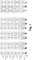
- Figure 1 illustrates an air separation system according to an embodiment of the present invention in a first representation.
- the air separation system is designated as a whole by 100. It comprises a first rectification arrangement 110, a second rectification arrangement 120 and a compressor arrangement 130.
- the first rectification arrangement 110 and the second Rectification arrangement 120 are each illustrated in the form of cold boxes, with a double column system 111 and an argon column 112 being indicated in the first rectification arrangement 110, and a nitrogen column 121 being indicated in the second rectification arrangement 120.
- a main heat exchanger 116 or 126 for cooling feed air is illustrated in each case.
- first rectification arrangement 110 Using the first rectification arrangement 110 and the second rectification arrangement 120, if in operation, high-purity nitrogen is generated, which is withdrawn in particular at the top of a (not separately designated) low-pressure column of the double column system 111 or the nitrogen column 121. Corresponding pure nitrogen streams are designated 1 and 2, respectively. Argon, which is also provided in the first rectification arrangement 110, as well as any other air products such as high-purity oxygen, are not shown separately.
- the compressor arrangement 130 here has three identically designated first compressor units 131, each illustrated in the form of two compressor symbols, and a second compressor unit 132, which is also illustrated with a compressor symbol.
- Each of the first compressor units 131 has several first compressor stages 131a and several second compressor stages 131b. Specific information regarding the compressor stages can be found above.
- the first compressor stages 131a are mechanically coupled to the second compressor stages 131b, for example via a common axis, as illustrated in each case with a vertical line, or via a gear.
- the first compressor stages 131a each suck in feed air in the form of feed air streams 3 via a filter unit 133, as does the second compressor unit 132 or its compressor stages 132a.
- An aftercooler can be connected downstream of the compressor stages 131a or 132a.
- the correspondingly compressed feed air can be combined in a collecting line 4 via downstream valves (not separately designated) depending on the operating mode and divided up via further valves (not separately designated) to a first prepurification unit 115 or a second prepurification unit 125, or fed to only one of these and then also divided up between the first rectification arrangement 110 and the second rectification arrangement 120. or only one of them.
- the feed air is freed of water and carbon dioxide in the prepurification units 115 and 125 and cooled in the main heat exchangers 116 and 126. Residual gas 5 from the rectification arrangements 110 and 120 can be used for regeneration in the prepurification units 115 and 125.
- the high-purity nitrogen stream 1 from the first rectification arrangement 110 is fed to a distribution line 6 and from there via valves (not separately designated) to a suction side of the second compressor stages 131b of the first compressor units 131, as well as in operation. A portion can be discharged from the air separation system 100 as product stream 7. After compression in the second compressor stages 131b, the high-purity nitrogen can be fed to a collecting line 8 and from here back into the first rectification arrangement 110 or discharged from the air separation system 100 as product stream 9.
- the first compressor stages 131a of at least one of the first compressor units 131 and the second compressor units 132 can be used for the feed air compression and the second compressor stages 131b of the at least one first compressor unit 131 can be used for the high-purity nitrogen compression.
- a first single operating mode the feed air is subjected to compression and fed only to the first rectification arrangement 110, and in this first single operating mode, at least a portion of the first compressor units 131 are operated and the second compressor unit 132 is not operated.
- a second single operating mode the feed air is subjected to compression and fed only to the second rectification arrangement 120, and in this second single operating mode, the second compressor unit 132 is operated and the first compressor units 131 are not operated.
- the combination operating mode and/or the first single operating mode may comprise a design operating mode in which all of the first compressor units are operated and one or more special operating modes in which at least one of the first compressor units is not operated.
- View A indicates a combination and design operating mode in which all of the first compressor units 131 and the second compressor unit 132 are in operation. In this case, theoretically 240,000 standard cubic meters per hour of feed air and 150,000 standard cubic meters per hour of high-purity nitrogen can be compressed.
- View B shows a first individual operating mode in the design operating mode in which the second compressor unit 132 is not in operation.
- a total feed air quantity of 120 standard cubic meters per hour of feed air is compressed in equal parts by means of the three first compressor units 131 or their first compressor stages 131a. The same applies to the total of 99,000 (or 100,000) standard cubic meters per hour of high-purity nitrogen, which are compressed using the second compressor stages 131b.
- View C also shows a first individual operating mode in which the second compressor unit 132 is not in operation. However, one of the first compressor units 131 is not in operation here either, so that a special operating mode is present.
- the total feed air quantity of 120,000 standard cubic meters per hour of feed air is compressed in equal parts by means of the two first compressor units 131 or their first compressor stages 131a. The same applies to the total of 100,000 standard cubic meters per hour of high-purity nitrogen, which is compressed using the second compressor stages 131b.
- Views B and C correspond in particular to an operating case in which a maximum amount of liquid is to be provided.
- the operating modes illustrated in views D and E are essentially the same as the operating modes illustrated in views B and C, but are adjusted, for example, to cover a maximum liquid oxygen content.
- the operating modes illustrated in views D and E are also essentially the same as the operating modes illustrated in views B and C, but with a reduced throughput.
- This first single operating and special operating mode can be used, for example, to cover a maximum gas quantity.
- the first individual operating and special operating mode can be set as shown in view H. In this mode, only one of the first compressor units 131 is in operation and delivers correspondingly small quantities.
- Views I and K show second operating modes in which only the second compressor unit 132 is in operation, and here additionally with different throughputs.
- View L again shows a combination operating mode.
Landscapes
- Engineering & Computer Science (AREA)
- Physics & Mathematics (AREA)
- Mechanical Engineering (AREA)
- Thermal Sciences (AREA)
- General Engineering & Computer Science (AREA)
- Separation By Low-Temperature Treatments (AREA)
Abstract
Es wird ein Verfahren zur kryogenen Erzeugung von Luftprodukten vorgeschlagen, bei dem ein Luftzerlegungssystem (100) mit einer ersten Rektifikationsanordnung (110), einer zweiten Rektifikationsanordnung (120) und einer Verdichteranordnung (130) verwendet wird, wobei die erste Rektifikationsanordnung (110) und die zweite Rektifikationsanordnung (120) jeweils eine auf einem Druckniveau von mehr als 2 bar betriebene Rektifikationskolonne aufweisen und das Verfahren einen Kombinationsbetriebsmodus umfasst, in dem unter Verwendung der Verdichteranordnung (130) Einsatzluft einer Einsatzluftverdichtung unterworfen und anschließend in Anteilen der ersten Rektifikationsanordnung (110) und der zweiten Rektifikationsanordnung (120) zugeführt wird, in dem unter Verwendung der ersten Rektifikationsanordnung (110) und der zweiten Rektifikationsanordnung (120) Hochreinstickstoff bereitgestellt wird, und in dem unter Verwendung der ersten Rektifikationsanordnung (110) bereitgestellte Hochreinstickstoff oder ein Teil hiervon mittels der Verdichteranordnung (130) einer Hochreinstickstoffverdichtung unterworfen wird. Es ist vorgesehen, dass die Verdichteranordnung (130) mehrere erste Verdichtereinheiten (131) und eine zweite Verdichtereinheit (132) aufweist, wobei jede der ersten Verdichtereinheiten (131) eine erste Verdichterstufe (131a) und eine zweite Verdichterstufe (131b) aufweist, in den ersten Verdichtereinheiten (131) die erste Verdichterstufe (131a) und die zweite Verdichterstufe (131b) mechanisch miteinander gekoppelt sind, und im Kombinationsbetriebsmodus die ersten Verdichterstufen (131a) der ersten Verdichtereinheiten (131) und die zweiten Verdichtereinheiten (132) für die Einsatzluftverdichtung und die zweiten Verdichterstufen (131b) der ersten Verdichtereinheiten (131) für die Hochreinstickstoffverdichtung verwendet werden. Ein entsprechendes Luftzerlegungssystem (100) ist ebenfalls Gegenstand der Erfindung.
Description
- Die vorliegende Erfindung betrifft ein Verfahren zur kryogenen Erzeugung von Luftprodukten und ein Luftzerlegungssystem.
- Die Herstellung von Luftprodukten in flüssigem oder gasförmigem Zustand durch Tieftemperaturzerlegung von Luft in Luftzerlegungsanlagen ist bekannt und beispielsweise bei H.-W. Häring (Hrsg.), Industrial Gases Processing, Wiley-VCH, 2006, insbesondere Abschnitt 2.2.5, "Cryogenic Rectification", beschrieben. Hinsichtlich des technischen Hintergrunds der vorliegenden Erfindung wird auf entsprechende Literatur verwiesen.
- Aus der
US 5,582,034 A ist ein Verfahren zur Herstellung von Stickstoff durch Tieftemperaturzerlegung von Luft bekannt, bei dem eine einzelne Rektifikationskolonne verwendet wird. Der Rektifikationskolonne werden aus einem unteren Bereich Flüssigkeiten mit unterschiedlichen Stickstoff- und Sauerstoffgehalten entnommen. Die Flüssigkeiten werden in einem Kondensatorverdampfer zur Kondensation von stickstoffreichem Kopfgas der Rektifikationskolonne verwendet, um auf diese Weise einen Rücklauf für die Rektifikationskolonne zu liefern. Nach Verdampfung der stickstoffreicheren und sauerstoffärmeren Flüssigkeit wird das gebildete Gas, oder ein Teil hiervon, rückverdichtet, abgekühlt, und in die Rektifikationskolonne rückgespeist. Dieses Gas wird auch als "Kreislaufstrom" bezeichnet. Die stickstoffärmere und sauerstoffreichere Flüssigkeit kann, ebenfalls nach entsprechender Verdampfung, in einer Entspannungsturbine entspannt werden, die einen Booster zur Rückverdichtung des Kreislaufstroms antreibt. Weiteres Kopfgas der Rektifikationskolonne wird als Stickstoffprodukt aus der Luftzerlegungsanlage ausgeleitet. - In der
WO 2021/180362 A1 sind ebenfalls unterschiedliche Verfahren dieser Art beschrieben, welche die Anmelderin auch als SPECTRA-Verfahren bezeichnet. Auf die Erläuterungen auf Seite 2 dieser Druckschrift und die dortige Beschreibung zuFigur 1 wird vorliegend ausdrücklich Bezug genommen. In derWO 2020/083528 A1 ist eine Vielzahl von Ausgestaltungen beschrieben, in denen beispielsweise Reinsauerstoffkolonnen und/oder Argonkolonnen zusätzlich zu der ursprünglich einzelnen Rektifikationskolonne zur Stickstoffgewinnung eingesetzt werden. Außerdem sind Doppelsäulenverfahren zur gleichzeitigen Gewinnung von Druckstickstoff und Argon bekannt, beispielsweise aus derWO 2023/030679 A1 . - Der Bedarf an Luftprodukten bei Verbrauchern wie beispielsweise Chipherstellern kann schwanken, und zwar hinsichtlich der Menge als auch der Art der Luftprodukte. So kann beispielsweise nur zu bestimmten Zeiten Argon benötigt werden oder eine Menge an benötigtem Reinstickstoff schwanken. Das jeweils geforderte Produktverhältnis von beispielsweise Argon und/oder Sauerstoff zu Stickstoff kann unter Umständen dazu führen, dass die Konstruktion von unterschiedlichen Anlagentypen der zuvor erläuterten Art hinsichtlich der Erstellungskosten vorteilhaft ist. Für entsprechende Zwecke können dabei auch Luftzerlegungssysteme mit mehreren Rektifikationsanordnungen zum Einsatz kommen, die nur zu bestimmten Zeiten gemeinsam und zu anderen Zeiten jeweils einzeln in Betrieb sind und entsprechende Luftprodukte liefern.
- Es besteht dabei jedoch weiterhin der Bedarf nach verbesserten Verfahren und Luftzerlegungssystemen dieser Art.
- Vor diesem Hintergrund werden ein Verfahren zur kryogenen Erzeugung von Luftprodukten und ein Luftzerlegungssystem mit den Merkmalen der jeweiligen unabhängigen Patentansprüche vorgeschlagen. Ausgestaltungen sind jeweils Gegenstand der abhängigen Patentansprüche und der nachfolgenden Beschreibung.
- Die in einer Luftzerlegungsanlage eingesetzten Vorrichtungen sind in der zitierten Fachliteratur, beispielsweise bei Häring in Abschnitt 2.2.5.6, "Apparatus", beschrieben. Sofern die nachfolgenden Definitionen nicht hiervon abweichen, wird daher zum Sprachgebrauch, der im Rahmen der vorliegenden Anmeldung verwendet wird, ausdrücklich auf die zitierte Fachliteratur verwiesen.
- Es wird ein Verfahren zur kryogenen Erzeugung von Luftprodukten vorgeschlagen, bei dem ein Luftzerlegungssystem mit einer ersten Rektifikationsanordnung, einer zweiten Rektifikationsanordnung und einer Verdichteranordnung verwendet wird, wobei die erste Rektifikationsanordnung und die zweite Rektifikationsanordnung jeweils eine Rektifikationskolonne aufweisen, die auf einem Druckniveau von mehr als 2 bar, insbesondere mehr als 3 bar, 4 bar oder 5 bar, und insbesondere bis zu 10 bar, 12 bar oder 15 bar, betrieben wird. Die erste und zweite Rektifikationsanordnung sind insbesondere insoweit entkoppelt, dass zwischen diesen keine Fluide ausgetauscht, d.h. von der ersten in die zweite Rektifiktionsanordnung und umgekehrt überführt werden, oder dies höchstens in sehr geringem Umfang, bspw. zu weniger als 10% einer Gesamtmenge der jeweils in der ersten und der zweite Rektifiktionsanordnung behandelten Fluide geschieht.
- Es ist vorgesehen, dass das Verfahren einen Kombinationsbetriebsmodus umfasst, wobei in dem Kombinationsbetriebsmodus unter Verwendung der Verdichteranordnung Einsatzluft einer Einsatzluftverdichtung unterworfen und danach in Anteilen der ersten Rektifikationsanordnung und der zweiten Rektifikationsanordnung zugeführt wird. Der ersten Rektifikationsanordnung kann insbesondere ein erster Hauptwärmetauscher und der zweiten Rektifikationsanrodnung insbesondere ein zweiter Hauptwärmetauscher zugeordnet sein, wobei der zur Speisung der ersten Rektifikationsanordnung verwendete Anteil der Luft durch den ersten und der zur Speisung der zweiten Rektifikationsanordnung verwendete Anteil der Luft separat dazu durch den zweiten Hauptwärmetauscher geführt wird, d.h. der zur Speisung der ersten Rektifikationsanordnung verwendete Anteil der Luft nicht durch den zweiten und der zur Speisung der zweiten Rektifikationsanordnung verwendete Anteil der Luft nicht durch den ersten Hauptwärmetauscher geführt wird. Auch hier können geringfügige Mengen von bspw. weniger als 10% der Einsatzluft abweichend behandelt werden.
- Ferner ist vorgesehen, dass in dem Kombinationsbetriebsmodus unter Verwendung der ersten Rektifikationsanordnung und der zweiten Rektifikationsanordnung Hochreinstickstoff bereitgestellt wird, und in dem Kombinationsbetriebsmodus der unter Verwendung der ersten Rektifikationsanordnung bereitgestellte Hochreinstickstoff oder ein Teil hiervon unter Verwendung der Verdichteranordnung einer Hochreinstickstoffverdichtung unterworfen wird.
- Unter "Hochreinstickstoff" wird vorliegend insbesondere gasförmiger Stickstoff mit einem sehr geringen Gehalt von Sauerstoff verstanden, der insbesondere im ein-, zwei- oder dreistelligen ppb-Bereich (parts per billion, Milliardstel Anteile), d.h. insbesondere bei weniger als 100, 50, 10, 5, 1, 0,5 oder 0,1 ppb, liegen kann. Ein Argongehalt kann typischerweise bei einem höheren Wert liegen, und zwar beispielsweise im ein-, zwei- oder dreistelligen ppm-Bereich (parts per million, Millionstel Anteile) oder weniger, d.h. insbesondere bei weniger als 100, 50, 10, 5, 1, 0,5 oder 0,1 ppb. Die Hochreinstickstoffverdichtung erfolgt insbesondere von einem Druck in einem Druckbereich von 2 bis 5 bar auf einen Druck in einem Druckbereich von 8 bis 15 bar. Die Einsatzluftverdichtung erfolgt insbesondere von Atmosphärendruck auf einen Druck in einem Druckbereich von 8 bis 15 bar. Der Hochreinstickstoff aus der zweiten Rektifikationsanordnung kann insbesondere unverdichtet als Hochreinstickstoffprodukt bereitgestellt werden.
- Hierbei ist vorgesehen, dass die Verdichteranordnung mehrere erste Verdichtereinheiten und eine zweite Verdichtereinheit aufweist, wobei jede der ersten Verdichtereinheiten eine erste Verdichterstufe und eine zweite Verdichterstufe aufweist, in jeder der ersten Verdichtereinheiten die erste Verdichterstufe und die zweite Verdichterstufe mechanisch miteinander gekoppelt sind, und in dem Kombinationsbetriebsmodus die ersten Verdichterstufen der ersten Verdichtereinheiten und die zweite Verdichtereinheit für die Einsatzluftverdichtung und die zweiten Verdichterstufen der ersten Verdichtereinheiten für die Hochreinstickstoffverdichtung verwendet werden.
- Ein "Verdichter" bzw. eine "Verdichtereinheit" ist im hier zugrunde gelegten Verständnis eine Vorrichtung, die zum Verdichten wenigstens eines gasförmigen Stroms von wenigstens einem Eingangsdruck, bei dem dieser dem Verdichter zugeführt wird, auf wenigstens einen Enddruck, bei dem dieser dem Verdichter entnommen wird, eingerichtet ist. Ein Verdichter bildet dabei generell eine bauliche Einheit, die jedoch mehrere "Verdichterstufen" in Form von Kolben-, Schrauben- und/oder Schaufelrad- bzw. Turbinenanordnungen (also Axial- oder Radialverdichterstufen) aufweisen kann. Dies gilt auch insbesondere für den "Haupt(luft)verdichter" einer Luftzerlegungsanlage, der sich dadurch auszeichnet, dass durch diesen die gesamte oder der überwiegende Anteil der in die Luftzerlegungsanlage eingespeisten Luftmenge, also der gesamte Einsatzluftstrom, verdichtet wird. Insbesondere werden entsprechende Verdichterstufen mittels eines gemeinsamen Antriebs, beispielsweise über eine gemeinsame Welle, angetrieben. Nachfolgend ist von "Verdichtereinheiten" die Rede, wobei bestimmte Verdichtereinheiten für unterschiedliche Verdichtungszwecke verwendete Verdichterstufen aufweisen kann und diese Verdichterstufen mechanisch miteinander gekoppelt sind, beispielsweise über eine gemeinsame Welle.
- Die vorliegende Erfindung betrifft in ihren unterschiedlichen Ausgestaltungen insbesondere eine hinsichtlich der Erstellungskosten verbesserte Möglichkeit zur Bereitstellung von Einsatzluft für unterschiedliche Rektifikationsanordnung und gleichzeitig zur Verdichtung eines Hochreinstickstoffprodukts. Den nachfolgenden Erläuterungen liegen Systeme mit zwei Rektifikationsanordnungen zugrunde, von denen eine mit einer Doppelkolonne ausgebildet ist und ein Argongewinnungssystem aufweist und die andere in Form einer SPECTRA-Einheit ausgebildet ist und kein Argongewinnungssystem aufweist. Das hier vorgeschlagene Verfahren bzw. ein entsprechendes System ist dabei erweiterbar, insbesondere mit einer weiteren SPECTRA-Einheit zur Stickstoffgewinnung.
- Eine SPECTRA-Einheit mit Argongewinnung ist herkömmlicherweise (zur Verringerung der Erstellungskosten) mit einem vierstufigen Hauptluftverdichter und einem zweistufigen Stickstoffverdichter in Form einer Kombinationsmaschine ausgestattet. Eine SPECTRA-Einheit ohne Argongewinnung ist herkömmlicherweise mit einem drei- oder vierstufigen Hauptluftverdichter ausgestattet.
- Die vorliegende Erfindung wurde insbesondere für ein Anforderungsprofil mit einer Luftverdichteranordnung von N+2 entwickelt. Diese soll insbesondere eine Reduktion von 50% in der gesamten Gasversorgung ermöglichen, was zu einer in Betrieb befindlichen 50%-Maschinen für jede Anlage führt. Es soll ferner möglich sein, jede der Einheiten im Falle einer Wartung/Ausfallzeit der anderen Einheit zu betreiben. Eine herkömmliche Lösung würde daher die Verwendung von N+2 Maschinen, d.h. 2+2 für die SPECTRA-Einheit mit Argongewinnung und 2+2 für die SPECTRA-Einheit ohne Argongewinnung, und damit acht Maschinen insgesamt, führen. Ausgestaltungen der vorliegenden Erfindung bieten eine Lösung, um die Anzahl der installierten Maschinen auf ein Minimum zu reduzieren und trotzdem einen effizienten und flexiblen Betrieb insgesamt sicherzustellen.
- Zur Argongewinnung können Luftzerlegungsanlagen mit sogenannten Roh- und Reinargonkolonnen eingesetzt werden. Ein Beispiel ist bei Häring (s.o.) in Figur 2.3A veranschaulicht und ab Seite 26 im Abschnitt "Rectification in the Low-pressure, Crude and Pure Argon Column" sowie ab Seite 29 im Abschnitt "Cryogenic Production of Pure Argon" beschrieben. In einer herkömmlichen Rohargonkolonne wird Rohargon gewonnen und in einer nachgeschalteten Reinargonkolonne zu Reinargon aufbereitet. Grundsätzlich kann zur Argongewinnung auch auf eine Reinargonkolonne verzichtet werden, wenn die betreffenden Rektifikationskolonnen entsprechend angepasst werden. Reinargon kann beispielsweise aus der Rohargonkolonne bzw. einer vergleichbaren Rektifikationskolonne weiter unterhalb als das herkömmlicherweise in die Reinargonkolonne überführte Fluid abgezogen werden, wobei ein oberhalb der Entnahmestelle angeordneter Abschnitt zur Stickstoffabtrennung dient. Zuvor und nachfolgend werden auch die Begriffe "Argongewinnungskolonne" und "Argongewinnungssystem" verwendet.
- Die Erfindung ermöglicht eine Erstellungs- und Betriebskostenreduzierung durch Einhaltung der Flexibilität und der Produktanforderungen durch eine geschickte Verschaltung von Luft- und Hochreinstickstoffverdichtung und eine intelligente Definition der Verdichtungsanforderungen. Mindestens einer der Verdichter, d.h. die zweite Verdichtereinheit, ist dabei kein Kombinationsverdichter und damit nur für die Verdichtung von Luft eingerichtet.
- Insbesondere kann bzw. können eine, mehrere oder alle der ersten Verdichtereinheiten zwei bis vier der ersten Verdichterstufen und/oder zwei bis vier der zweiten Verdichterstufen aufweisen. Hierbei können in einer, meheren oder allen ersten Verdichtereinheiten eine, mehrere oder alle der ersten Verdichterstufen mit einer, mehreren oder allen der zweiten Verdichterstufe mechanisch gekoppelt sein. Auch eine paarweise Kopplung jeweils einer ersten und einer zweiten Verdichterstufe kann vorgesehen sein. Die obigen Erläuterungen zu "der" ersten Verdichterstufe und "der" zweiten Verdichterstufe betreffen daher auch solche Ausgestaltungen.
- Ebenfalls kann in Ausgestaltungen der Erfindung die Verdichteranordnung zwei oder mehr zweite Verdichtereinheiten aufweisen, von denen dann eine, mehrere oder alle betrieben werden können wie zuvor erläutert.
- Die ersten Verdichterstufen unterschiedlicher erster Verdichtereinheiten können dabei voneinander entkoppelt sein und die zweiten Verdichterstufen unterschiedlicher erster Verdichtereinheiten können ebenfalls voneinander entkoppelt sein.
- Insbesondere weist die erste Rektifikationsanordnung eine Doppelkolonneneinheit mit einer Druckkolonne und einer Niederdruckkolonne sowie einer Argongewinnungskolonne auf, wobei der unter Verwendung der ersten Rektifikationsanordnung bereitgestellte Hochreinstickstoff aus der Doppelkolonneneinheit, insbesondere am Kopf einer Druckkolonne und/oder Niederdruckkolonne, entnommen wird, und wobei der Argongewinnungskolonne ein Argonprodukt entnommen wird.. Die Druck- und Niederdruckkolonne können dabei in einem gemeinsamen Mantel verbaut, aber auch separat zueinander bereitgestellt werden. Die Niederdruckkolonne kann einteilig oder zweiteilig ausgebildet sein. Der Betriebsdruck der Druckkolonne kann insbesondere bei 9 bis 14,5 bar liegen.
- Auch die Argonkolonne kann einteilig oder zweiteilig ausgebildet sein. Die erste Rektifikationsanordnung kann eine oder mehrere Rektifikationskolonnen zur Herstellung von ultrahochreinem Sauerstoff und/oder zur Herstellung eines Krypton-/Xenon-Rohgemischs und/oder zur Herstellung eines Helium-/Neon-Rohgemischs umfassen.
- Die zweite Rektifikationsanordnung weist insbesondere eine Stickstoffkolonne, aus der der unter Verwendung der zweiten Rektifikationsanordnung bereitgestellte Hochreinstickstoff entnommen wird, und keine Argongewinnungskolonne auf. Es kann sich insbesondere um eine Rektifikationskolonne handeln, wie sie für ein SPECTRA-System bekannt ist. Insbesondere kann in der zweiten Rektifikationsanordnung genau eine Stickstoffkolonne vorhanden sein, und zwar als einzige Kolonne, oder es können eine oder mehrere Stickstoffkolonnen zusammen mit einer oder mit mehreren weiteren Kolonnen vorhanden sein, insbesondere für die Produktion von ultrahochreinem Sauerstoff, wie eingangs erläutert.
- Die erste Rektifikationsanordnung bzw. deren Doppelkolonneneinheit wird insbesondere betrieben, wie für entsprechende Anordnungen an sich bekannt. Der Stickstoffkolonne der zweiten Rektifikationsanrodnung wird insbesondere Flüssigkeit entnommen, entspannt, gegen kondensierendes Kopfgas der zweiten Stickstoffkolonne verdampft, und zumindest zum Teil einer Rückverdichtung unterworfen und in die Stickstoffkolonne zurückgespeist. Die zweite Stickstoffkolonne ist dabei insbesondere vom Typ jener Rektifikationskolonnen, wie sie eingangs unter Bezug auf Druckschriften wie die
US 5,582,034 A , dieWO 2021/180362 A1 und dieWO 2020/083528 A1 bzw. das SPECTRA-Verfahren beschrieben wurden. Die erwähnte Rückverdichtung kann dabei insbesondere unter Verwendung eines mit einer Entspannungsturbine gekoppelten Boosters eines Turbinenboosters erfolgen. - Eine "Entspannungsturbine" bzw. "Entspannungsmaschine", die über eine gemeinsame Welle mit weiteren Entspannungsturbinen oder Energiewandlern wie Ölbremsen, Generatoren oder Verdichtern gekoppelt sein kann, ist zur Entspannung eines gasförmigen oder zumindest teilweise flüssigen Stroms eingerichtet. Insbesondere können Entspannungsturbinen zum Einsatz in der vorliegenden Erfindung als Turboexpander ausgebildet sein. Wird ein Verdichter mit einer oder mehreren Entspannungsturbinen angetrieben, jedoch ohne extern, beispielsweise mittels eines Elektromotors, zugeführte Energie, wird der Begriff "turbinengetriebener Verdichter" oder alternativ "Turbinenbooster" verwendet.
- Der Stickstoffkolonne (in der zweiten Rektifikationsanordnung) können aus einem unteren Bereich insbesondere Flüssigkeiten mit unterschiedlichen Stickstoff- und Sauerstoffgehalten entnommen werden, von denen die Flüssigkeit mit dem höheren Stickstoffgehalt insbesondere die bereits erwähnte Flüssigkeit sein kann. Die Flüssigkeiten können in einem Kondensatorverdampfer zur Kondensation des stickstoffreichen Kopfgases der Rektifikationskolonne verwendet werden, um auf diese Weise einen Rücklauf für die Stickstoffkolonne zu liefern. Nach Verdampfung der stickstoffreicheren und sauerstoffärmeren Flüssigkeit kann das gebildete Gas, oder ein Teil hiervon, rückverdichtet, abgekühlt, und in die Stickstoffkolonne rückgespeist. Dieses Gas wird auch als "Kreislaufstrom" bezeichnet. Die stickstoffärmere und sauerstoffreichere Flüssigkeit kann, ebenfalls nach entsprechender Verdampfung, in einer Entspannungsturbine entspannt werden, die einen Booster zur Rückverdichtung des Kreislaufstroms antreibt. Weiteres Kopfgas der Stickstoffkolonne kann als das Stickstoffprodukt aus der Luftzerlegungsanlage ausgeleitet werden.
- In einer Ausgestaltung der Erfindung kann jede der ersten Verdichtereinheiten, wie erwähnt, bis zu vier der ersten Verdichterstufen und bis zu zwei der zweiten Verdichterstufen aufweisen. Eine entsprechende Verteilung von Verdichterstufen bzw. der Einsatz für die jeweiligen Zwecke kann insbesondere eine Anpassung an die Mengenverhältnisse von Stickstoff und anderen Luftkomponenten in atmosphärischer Luft erfolgen.
- Das Verfahren umfasst in Ausgestaltungen insbesondere einen ersten Einzelbetriebsmodus, in dem die Einsatzluft der Verdichtung unterworfen und nur der ersten Rektifikationsanordnung zugeführt wird, und in dem zumindest ein Teil ersten Verdichtereinheiten betrieben wird und die zweite Verdichtereinheit nicht betrieben wird. In entsprechenden Ausgestaltungen kann also insbesondere die SPECTRA-Einheit ohne Argongewinnung außer Betrieb gesetzt werden, beispielsweise um diese warten zu können oder die bereitgestellte Gesamtmenge an Stickstoff zu reduzieren.
- Insbesondere ist in Ausgestaltungen auch ein zweiter Einzelbetriebsmodus vorgesehen, in dem die Einsatzluft der Verdichtung unterworfen und nur der zweiten Rektifikationsanordnung zugeführt wird, und in dem die zweite Verdichtereinheit betrieben wird und die ersten Verdichtereinheiten nicht betrieben werden. Auf diese Weise kann insbesondere von einer Kombinationsproduktion von Stickstoff und Argon auf eine reine Stickstoffproduktion unter Reduktion der Stickstoffmenge umgestellt werden.
- Der Kombinationsbetriebsmodus und/oder der erste Einzelbetriebsmodus kann bzw. können insbesondere einen Auslegungsbetriebsmodus, in dem alle ersten Verdichtereinheiten betrieben werden, und einen oder mehrere Sonderbetriebsmodi, in dem zumindest eine der ersten Verdichtereinheiten nicht betrieben wird, umfassen. Entsprechende Ausgestaltungen ermöglichen eine Anpassung an unterschiedliche Produktanforderungen und betriebliche Anforderungen.
- Der Sonderbetriebsmodus oder zumindest einer der mehreren Sonderbetriebsmodi kann insbesondere ein Wartungsbetriebsmodus sein, in dem eine Menge der Einsatzluft, die der Verdichtung unterworfen wird, gleich wie in dem Auslegungsbetriebsmodus ist. In einer derartigen Ausgestaltung kann ein Durchsatz der weiter aktiv betriebenen Verdichtereinheiten erhöht werden.
- Der Sonderbetriebsmodus oder zumindest einer der mehreren Sonderbetriebsmodi kann insbesondere aber auch ein Lastreduktionsbetriebsmodus sein, in dem eine Menge der Einsatzluft, die der Verdichtung unterworfen wird, geringer als in dem Auslegungsbetriebsmodus ist. In einer derartigen Ausgestaltungen wird der Durchsatz insgesamt reduziert.
- Weitere Betriebsmodi können vorgesehen sein, beispielsweise ein Wartungsmodus, bei dem die erste und zweite Rektifikationsanordnungen in Betrieb sind und zwei oder drei der ersten oder zweiten Verdichterstufen in Betrieb sind. Dabei kann können die zweiten Verdichterstufen) im internen Kreislauf betrieben werden. Im weiteren gibt es die Möglichkeit, dass nur die zweite Rektifikationsordnung in Betrieb ist und nur ein Kombiverdichter mit erster und zweiter Verdichterstufe in Betrieb ist, wobei die zweite Verdichterstufe im internen Kreislauf betrieben wird bzw. werden (also im "idle" Modus). Entsprechendes gilt auch für mehrere erste und zweite Verdichterstufen, falls in einer ersten Verdichteranordnung in einer Ausgestaltung vorgesehen.
- Es können zwei Prepurification Units und zwei Hauptwärmetauschereinheiten bekannter Art verwendet werden. Der ersten Rektifikationsanordnung kann eine der zwei Prepurification Units und eine der zwei Hauptwärmetauschereinheiten zugeordnet sein, und der zweiten Rektifikationsanordnung kann die jeweils andere der zwei Prepurification Units und der zwei Hauptwärmetauschereinheiten zugeordnet sein. Unter einer "Rektifikationsanordnung" seien also im hier zugrunde liegenden Verständnis die entsprechenden Kombinationen aus Apparaten verstanden werden.
- Das vorgeschlagene Luftzerlegungssystem zur kryogenen Erzeugung von Luftprodukten umfasst eine erste Rektifikationsanordnung, eine zweite Rektifikationsanordnung und eine Verdichteranordnung, wobei die erste Rektifikationsanordnung und die zweite Rektifikationsanordnung jeweils eine für einen Betrieb bei mehr als 2 bar eingerichtete Rektifikationskolonne aufweisen und das Luftzerlegungssystem dafür eingerichtet ist, einen Kombinationsbetriebsmodus durchzuführen und in diesem unter Verwendung der Verdichteranordnung Einsatzluft einer Einsatzluftverdichtung zu unterwerfen und danach in Anteilen der ersten Rektifikationsanordnung und der zweiten Rektifikationsanordnung zuzuführen, unter Verwendung der ersten Rektifikationsanordnung und der zweiten Rektifikationsanordnung Hochreinstickstoff bereitzustellen, und den unter Verwendung der ersten Rektifikationsanordnung bereitgestellten Hochreinstickstoff oder einen Teil hiervon unter Verwendung der Verdichteranordnung einer Hochreinstickstoffverdichtung zu unterwerfen.
- Die vorgeschlagene Verdichteranordnung umfasst mehrere erste Verdichtereinheiten und eine zweite Verdichtereinheit, wobei jede der ersten Verdichtereinheiten eine erste Verdichterstufe und eine zweite Verdichterstufe aufweist, und in jeder der ersten Verdichtereinheiten die erste Verdichterstufe und die zweite Verdichterstufe mechanisch miteinander gekoppelt sind. Das Luftzerlegungssystem ist dafür eingerichtet, in dem Kombinationsbetriebsmodus die ersten Verdichterstufen der ersten Verdichtereinheiten und die zweite Verdichtereinheit für die Einsatzluftverdichtung und die zweiten Verdichterstufen der ersten Verdichtereinheiten für die Hochreinstickstoffverdichtung zu verwenden.
- Zu weiteren Merkmalen und Vorteilen eines entsprechenden Luftzerlegungssystems und Ausgestaltungen hiervon sei auf die obigen Erläuterungen betreffend das erfindungsgemäß vorgeschlagenen Verfahren und seinen Ausgestaltungen ausdrücklich verwiesen, da diese hierfür in gleicher Weise gelten.
- Entsprechendes gilt auch für ein Luftzerlegungssystem das gemäß einer Ausgestaltung der Erfindung dazu eingerichtet ist, ein Verfahren gemäß einer beliebigen Ausgestaltung der vorliegenden Erfindung durchzuführen.
- Ausführungsformen der Erfindung werden nachfolgend rein beispielhaft unter Bezugnahme auf die beigefügte Zeichnung unter Erläuterung des technischen Hintergrunds beschrieben.
-
Figur 1 veranschaulicht ein Luftzerlegungssystem gemäß einer Ausführungsform der vorliegenden Erfindung in vereinfachter schematischer Darstellung. - Figur 2 veranschaulicht Betriebsmodi eines Luftzerlegungssystems gemäß einer Ausführungsform der vorliegenden Erfindung.
- Die nachfolgend beschriebenen Ausführungsformen werden lediglich zu dem Zweck beschrieben, den Leser beim Verständnis der beanspruchten und zuvor erläuterten Merkmale zu unterstützen. Sie stellen lediglich repräsentative Beispiele dar und sollen hinsichtlich der Merkmale der Erfindung nicht abschließend und/oder beschränkend betrachtet werden. Es versteht sich, dass die zuvor und nachfolgend beschriebenen Vorteile, Ausführungsformen, Beispiele, Funktionen, Merkmale, Strukturen und/oder anderen Aspekte nicht als Beschränkungen des Umfangs der Erfindung, wie er in den Ansprüchen definiert ist, oder als Beschränkungen von Äquivalenten zu den Ansprüchen zu betrachten sind, und dass andere Ausführungsformen verwendet und Änderungen vorgenommen werden können, ohne vom Umfang der beanspruchten Erfindung abzuweichen.
- Unterschiedliche Ausführungsformen der Erfindung können weitere zweckmäßige Kombinationen der beschriebenen Elemente, Komponenten, Merkmale, Teile, Schritte, Mittel usw. umfassen, aufweisen, aus ihnen bestehen oder im Wesentlichen aus ihnen bestehen, auch wenn solche Kombinationen hier nicht spezifisch beschrieben sind. Darüber hinaus kann die Offenbarung andere Erfindungen umfassen, die gegenwärtig nicht beansprucht sind, die aber in Zukunft beansprucht werden können, insbesondere wenn sie vom Umfang der unabhängigen Ansprüche umfasst sind.
- Erläuterungen, die sich auf Vorrichtungen, Apparate, Anordnungen, Systeme usw. gemäß Ausführungsformen der vorliegenden Erfindung beziehen, können auch für Verfahren, Prozesse, Methoden usw. gemäß den Ausführungsformen der vorliegenden Erfindung gelten und umgekehrt. Gleiche, gleich wirkende, in ihrer Funktion einander entsprechende, baulich identisch oder vergleichbar aufgebaute Elemente, Verfahrensschritte usw. können mit identischen Bezugszeichen angegeben sein.
-
Figur 1 veranschaulicht ein Luftzerlegungssystem gemäß einer Ausführungsform der vorliegenden Erfindung in einer ersten Darstellung. - Das Luftzerlegungssystem ist insgesamt mit 100 bezeichnet. Es umfasst eine erste Rektifikationsanordnung 110, eine zweite Rektifikationsanordnung 120 und eine Verdichteranordnung 130. Die erste Rektifikationsanordnung 110 und die zweite Rektifikationsanordnung 120 sind jeweils in Form von Coldboxen veranschaulicht, wobei in der ersten Rektifikationsanordnung 110 ein Doppelkolonnensystem 111 und eine Argonkolonne 112 angedeutet sind, und wobei in der zweiten Rektifikationsanordnung 120 eine Stickstoffkolonne 121 angedeutet istFerner ist jeweils ein Hauptwärmetauscher 116 bzw. 126 zur Abkühlung von Einsatzluft veranschaulicht. Für spezifische Ausgestaltungen der genannten Kolonnen(systeme) sei auf den eingangs erwähnten Stand der Technik ausdrücklich verwiesen. Unter Verwendung der ersten Rektifikationsanordnung 110 und der zweiten Rektifikationsanordnung 120 wird, sofern in Betrieb, jeweils Hochreinstickstoff erzeugt, der insbesondere am Kopf einer (nicht gesondert bezeichneten) Niederdruckkolonne des Doppelkolonnensystems 111 bzw. der Stickstoffkolonne 121 abgezogen wird. Entsprechende Reinstickstoffströme sind mit 1 bzw. 2 bezeichnet. In der ersten Rektifikationsanordnung 110 ebenfalls bereitgestelltes Argon ist, ebenso wie ggf. weitere Luftprodukte wie Hochreinsauerstoff, nicht gesondert dargestellt.
- Die Verdichteranordnung 130 weist hier drei identisch bezeichnete und jeweils in Form zweier Verdichtersymbole veranschaulichte erste Verdichtereinheiten 131 und eine zweite Verdichtereinheit 132 auf, die ebenfalls mit einem Verdichtersymbol veranschaulicht ist. Jede der ersten Verdichtereinheiten 131 weist mehrere erste Verdichterstufen 131a und mehrere zweite Verdichterstufen 131b auf. Konkrete Angaben hinsichtlich der Verdichterstufen finden sich oben. In jeder der ersten Verdichtereinheiten 131 sind die ersten Verdichterstufen 131a mit den zweiten Verdichterstufen 131b mechanisch gekoppelt, beispielsweise über eine gemeinsame Achse, wie jeweils mit einer vertikalen Linie veranschaulicht, oder über ein Getriebe.
- Die ersten Verdichterstufen 131a saugen, wenn im Betrieb, jeweils über eine Filtereinheit 133 Einsatzluft in Form von Einsatzluftströmen 3 an, ebenso wie die zweite Verdichtereinheit 132 bzw. deren Verdichterstufen 132a. Den Verdichterstufen 131a bzw. 132a kann jeweils ein Nachkühler nachgeschaltet sein. Über ebenfalls nachgeschaltete, nicht gesondert bezeichnete Ventile kann die entsprechend verdichtete Einsatzluft je nach Betriebsmodus in einer Sammelleitung 4 zusammengefasst und über weitere, nicht gesondert bezeichnete Ventile auf eine erste Prepurification Unit 115 bzw. eine zweite Prepurification Unit 125 aufgeteilt oder nur einer hiervon zugeführt und anschließend ebenfalls auf die erste Rektifikationsanordnung 110 und die zweite Rektifikationsanordnung 120 aufgeteilt oder nur einer hiervon zugeführt werden. Die Einsatzluft wird dabei in den Prepurification Units 115 bzw. 125 von Wasser und Kohlendioxid befreit und in den Hauptwärmetauschern 116 bzw. 126 gekühlt. Restgas 5 aus den Rektifikationsanordnungen 110 bzw. 120 kann dabei zur Regenerierung in den Prepurification Units 115 bzw. 125 eingesetzt werden.
- Der Hochreinstickstoffstrom 1 aus der ersten Rektifikationsanordnung 110 wird einer Verteilerleitung 6 zugeführt und von dort aus über nicht gesondert bezeichnete Ventile einer Saugseite der zweiten Verdichterstufen 131b der ersten Verdichtereinheiten 131, sowie jeweils in Betrieb. Ein Teil kann als Produktstrom 7 aus dem Luftzerlegungssystem 100 ausgeleitet werden. Nach der Verdichtung in den zweiten Verdichterstufen 131b kann der Hochreinstickstoff einer Sammelleitung 8 zugeführt und von hier zurück in die erste Rektifikationsanordnung 110 bzw. als Produktstrom 9 aus dem Luftzerlegungssystem 100 ausgeleitet werden.
- Wie bereits erwähnt, können in einem Kombinationsbetriebsmodus die ersten Verdichterstufen 131a zumindest einer der ersten Verdichtereinheiten 131 und die zweite Verdichtereinheiten 132 für die Einsatzluftverdichtung und die zweiten Verdichterstufen 131b der zumindest einen ersten Verdichtereinheit 131 für die Hochreinstickstoffverdichtung verwendet werden. In einem ersten Einzelbetriebsmodus wird die Einsatzluft der Verdichtung unterworfen und nur der ersten Rektifikationsanordnung 110 zugeführt, und in diesem ersten Einzelbetriebsmodus wird zumindest ein Teil ersten Verdichtereinheiten 131 betrieben und die zweite Verdichtereinheit 132 wird nicht betrieben. In einem zweiten Einzelbetriebsmodus wird die Einsatzluft der Verdichtung unterworfen und nur der zweiten Rektifikationsanordnung 120 zugeführt, und in diesem zweiten Einzelbetriebsmodus wird die zweite Verdichtereinheit 132 betrieben und die ersten Verdichtereinheiten 131 werden nicht betrieben. Der Kombinationsbetriebsmodus und/oder der erste Einzelbetriebsmodus kann einen Auslegungsbetriebsmodus umfassen, in dem alle ersten Verdichtereinheiten betrieben werden, und einen oder mehrere Sonderbetriebsmodi, in dem zumindest eine der ersten Verdichtereinheiten nicht betrieben wird.
- Entsprechende Betriebsmodi werden nachfolgend unter Bezugnahme auf Figur 2 erläutert, in der in elf Ansichten A bis L der ersten Verdichtereinheiten 131 mit den ersten und zweiten Verdichterstufen 131a, 131b und der zweiten Verdichtereinheiten 132 mit den Verdichterstufen 132a veranschaulicht sind. Die Verdichtereinheiten 131 und 132 mit den Verdichterstufen 131a, 131b und 132a sind nur in Ansicht A dargestellt. Nicht in Betrieb befindliche Verdichtereinheiten sind durchkreuzt dargestellt. Innerhalb der die Verdichterstufen 131a, 131b und 132a veranschaulichenden Symbole befindliche Zahlen bezeichnen den jeweiligen Durchsatz, beispielsweise in tausend Normkubikmetern pro Stunde. Es handelt sich lediglich um illustrative Beispiele, die den Gegenstand der Erfindung nicht einschränken.
- Ansicht A bezeichnet einen Kombinations- und Auslegungsbetriebsmodus, in dem alle ersten Verdichtereinheiten 131 und die zweite Verdichtereinheit 132 in Betrieb ist. Hierbei können theoretisch 240.000 Normkubikmeter pro Stunde Einsatzluft und 150.000 Normkubikmeter pro Stunde Hochreinstickstoff verdichtet werden.
- In Ansicht B ist ein erster Einzelbetriebsmodus im Auslegungsbetriebsmodus dargestellt, in dem die zweite Verdichtereinheit 132 nicht in Betrieb ist. Eine Gesamteinsatzluftmenge von 120 Normkubikmetern pro Stunde Einsatzluft wird dabei zu gleichen Teilen mittels der drei ersten Verdichtereinheiten 131 bzw. deren erster Verdichterstufen 131a verdichtet. Entsprechendes gilt für die insgesamt 99.000 (bzw. 100.000) Normkubikmeter pro Stunde Hochreinstickstoff, die unter Verwendung der zweiten Verdichterstufen 131b verdichtet werden.
- In Ansicht C ist weiter ein erster Einzelbetriebsmodus dargestellt, in dem die zweite Verdichtereinheit 132 nicht in Betrieb ist. Allerdings ist auch hier eine der ersten Verdichtereinheiten 131 nicht in Betrieb, so dass ein Sonderbetriebsmodus vorliegt. Die Gesamteinsatzluftmenge von 120.000 Normkubikmetern pro Stunde Einsatzluft wird dabei zu gleichen Teilen mittels der zwei ersten Verdichtereinheiten 131 bzw. deren erster Verdichterstufen 131a verdichtet. Entsprechendes gilt für die insgesamt 100.000 Normkubikmeter pro Stunde Hochreinstickstoff, die unter Verwendung der zweiten Verdichterstufen 131b verdichtet werden.
- Die Ansichten B und C entsprechen dabei insbesondere einem Betriebsfall, in dem eine maximale Flüssigkeitsmenge bereitgestellt werden soll.
- Die in den Ansichten D und E veranschaulichten Betriebsmodi gleichen im Wesentlichen den in den Ansichten B und C veranschaulichten Betriebsmodi, werden aber z.B. zur Deckung eines maximalen Flüssigsauerstoffgehalts eingestellt.
- Die in den Ansichten D und E veranschaulichten Betriebsmodi gleichen ebenfalls im Wesentlichen den in den Ansichten B und C veranschaulichten Betriebsmodi, wobei jedoch ein Durchsatz abgesenkt wird. Dieser erste Einzelbetriebs- und Sonderbetriebsmodus kann z.B. zur Deckung einer maximalen Gasmenge dienen.
- Besteht in gewissen Zeiten nur ein stark reduzierter Bedarf an entsprechenden Luftprodukten, kann der erste Einzelbetriebs- und Sonderbetriebsmodus gemäß Ansicht H eingestellt werden. In diesem ist nur eine der ersten Verdichtereinheiten 131 in Betrieb und liefert entsprechend geringe Mengen.
- Die Ansichten I und K zeigen zweite Betriebsmodi, in denen nur die zweite Verdichtereinheit 132 und hier zusätzlich mit unterschiedlichen Durchsätzen, in Betrieb sind. Ansicht L zeigt wiederum einen Kombinationsbetriebsmodus.
Claims (14)
- Verfahren zur kryogenen Erzeugung von Luftprodukten, bei dem ein Luftzerlegungssystem (100) mit einer ersten Rektifikationsanordnung (110), einer zweiten Rektifikationsanordnung (120) und einer Verdichteranordnung (130) verwendet wird, wobei die erste Rektifikationsanordnung (110) und die zweite Rektifikationsanordnung (120) jeweils eine auf einem Druckniveau von mehr als 2 bar betriebene Rektifikationskolonne aufweisen und das Verfahren einen Kombinationsbetriebsmodus umfasst, in dem unter Verwendung der Verdichteranordnung (130) Einsatzluft einer Einsatzluftverdichtung unterworfen und anschließend in Anteilen der ersten Rektifikationsanordnung (110) und der zweiten Rektifikationsanordnung (120) zugeführt wird, in dem unter Verwendung der ersten Rektifikationsanordnung (110) und der zweiten Rektifikationsanordnung (120) Hochreinstickstoff bereitgestellt wird, und in dem unter Verwendung der ersten Rektifikationsanordnung (110) bereitgestellte Hochreinstickstoff oder ein Teil hiervon unter Verwendung der Verdichteranordnung (130) einer Hochreinstickstoffverdichtung unterworfen wird, dadurch gekennzeichnet, dass die Verdichteranordnung (130) mehrere erste Verdichtereinheiten (131) und eine zweite Verdichtereinheit (132) aufweist, wobei jede der ersten Verdichtereinheiten (131) eine erste Verdichterstufe (131a) und eine zweite Verdichterstufe (131b) aufweist, in den ersten Verdichtereinheiten (131) die erste Verdichterstufe (131a) und die zweite Verdichterstufe (131b) mechanisch miteinander gekoppelt sind, und in dem Kombinationsbetriebsmodus- die ersten Verdichterstufen (131a) der ersten Verdichtereinheiten (131) und die zweite Verdichtereinheit (132) für die Einsatzluftverdichtung und- die zweiten Verdichterstufen (131b) der ersten Verdichtereinheiten (131) für die Hochreinstickstoffverdichtung verwendet werden.
- Verfahren nach Anspruch 1, bei dem eine, mehrere oder alle der ersten Verdichtereinheiten (131) zwei bis vier der ersten Verdichterstufen (131a) und/oder zwei bis vier der zweiten Verdichterstufen (131b) aufweisen.
- Verfahren nach Anspruch 1 oder 2, bei dem die Verdichteranordnung (130) zwei oder mehr der zweiten Verdichtereinheiten (132) aufweist.
- Verfahren nach einem der vorstehenden Ansprüche, bei dem die ersten Verdichterstufen (131a) unterschiedlicher erster Verdichtereinheiten (131) voneinander entkoppelt sind und die zweiten Verdichterstufen (131b) unterschiedlicher erster Verdichtereinheiten (131) voneinander entkoppelt sind.
- Verfahren nach einem der vorstehenden Ansprüche, bei dem die erste Rektifikationsanordnung (110) eine Doppelkolonneneinheit (111) und eine Argongewinnungskolonne (112) aufweist, wobei- der unter Verwendung der ersten Rektifikationsanordnung (110) bereitgestellte Hochreinstickstoff aus der Doppelkolonneneinheit (111) entnommen wird, und- der Argongewinnungskolonne (112) ein Argonprodukt entnommen wird, und bei dem die zweite Rektifikationsanordnung (120) eine Stickstoffkolonne (121), aus der der unter Verwendung der zweiten Rektifikationsanordnung (120) bereitgestellte Hochreinstickstoff entnommen wird, und keine Argongewinnungskolonne aufweist.
- Verfahren nach Anspruch 5, bei dem der Stickstoffkolonne (121) Flüssigkeit entnommen, entspannt, gegen kondensierendes Kopfgas der zweiten Stickstoffkolonne (121) verdampft, und zumindest zum Teil einer Rückverdichtung unterworfen und in die zweite Stickstoffkolonne (121) zurückgespeist wird.
- Verfahren nach einem der vorstehenden Ansprüche, das einen ersten Einzelbetriebsmodus umfasst, in dem die Einsatzluft der Verdichtung unterworfen und nur der ersten Rektifikationsanordnung (110) zugeführt wird, und in dem- zumindest ein Teil ersten Verdichtereinheiten (131) betrieben wird und- die zweite Verdichtereinheit (132) nicht betrieben wird.
- Verfahren nach Anspruch 7, das einen zweiten Einzelbetriebsmodus umfasst, in dem die Einsatzluft der Verdichtung unterworfen und nur der zweiten Rektifikationsanordnung (120) zugeführt wird, und in dem die zweite Verdichtereinheit (132) betrieben wird und die ersten Verdichtereinheiten (131) nicht betrieben werden.
- Verfahren nach Anspruch 7 oder Anspruch 8, bei dem der Kombinationsbetriebsmodus und/oder der erste Einzelbetriebsmodus einen Auslegungsbetriebsmodus, in dem alle ersten Verdichtereinheiten (131) betrieben werden, und einen oder mehrere Sonderbetriebsmodi, in dem zumindest eine der ersten Verdichtereinheiten (131) nicht betrieben wird, umfasst.
- Verfahren nach Anspruch 9, wobei der Sonderbetriebsmodus oder zumindest einer der mehreren Sonderbetriebsmodi ein Wartungsbetriebsmodus ist, in dem eine Menge der Einsatzluft, die der Verdichtung unterworfen wird, gleich wie in dem Auslegungsbetriebsmodus ist.
- Verfahren nach Anspruch 9 oder Anspruch 10, wobei der Sonderbetriebsmodus oder zumindest einer der mehreren Sonderbetriebsmodi ein Lastreduktionsbetriebsmodus ist, in dem eine Menge der Einsatzluft, die der Verdichtung unterworfen wird, geringer als in dem Auslegungsbetriebsmodus ist.
- Verfahren nach einem der vorstehenden Ansprüche, bei dem der ersten Rektifikationsanordnung (110) eine erste Prepurification Unit (115) und eine erste Hauptwärmetauschereinheit (116) zugeordnet ist, und bei dem der zweiten Rektifikationsanordnung (120) eine zweite Prepurification Unit (125) und eine zweite Hauptwärmetauschereinheit (126) zugeordnet ist.
- Luftzerlegungssystem (100) zur kryogenen Erzeugung von Luftprodukten mit einer ersten Rektifikationsanordnung (110), einer zweiten Rektifikationsanordnung (120) und einer Verdichteranordnung (130), wobei die erste Rektifikationsanordnung (110) und die zweite Rektifikationsanordnung (120) jeweils eine für einen Betrieb bei mehr als 2 bar eingerichtete Rektifikationskolonne aufweisen und das Luftzerlegungssystem (100) dafür eingerichtet ist, einen Kombinationsbetriebsmodus durchzuführen und in diesem unter Verwendung der Verdichteranordnung (130) Einsatzluft einer Einsatzluftverdichtung zu unterwerfen und danach in Anteilen der ersten Rektifikationsanordnung (110) und der zweiten Rektifikationsanordnung (110) zuzuführen, unter Verwendung der ersten Rektifikationsanordnung (110) und der zweiten Rektifikationsanordnung (110) Hochreinstickstoff bereitzustellen, und den unter Verwendung der ersten Rektifikationsanordnung (110) bereitgestellten Hochreinstickstoff oder einen Teil hiervon unter Verwendung der Verdichteranordnung (130) einer Hochreinstickstoffverdichtung zu unterwerfen, dadurch gekennzeichnet, dass die Verdichteranordnung (130) mehrere erste Verdichtereinheiten (131) und eine zweite Verdichtereinheit (132) aufweist, wobei jede der ersten Verdichtereinheiten (131) eine erste Verdichterstufe (131a) und eine zweite Verdichterstufe (131b) aufweist, und in den ersten Verdichtereinheiten (131) die erste Verdichterstufe (131a) und die zweite Verdichterstufe (131b) mechanisch miteinander gekoppelt sind, und wobei das Luftzerlegungssystem (100) dafür eingerichtet ist, in dem Kombinationsbetriebsmodus die ersten Verdichterstufen (131a) der ersten Verdichtereinheiten (131) und die zweite Verdichtereinheit (132) für die Einsatzluftverdichtung und die zweiten) Verdichterstufen (131b) der ersten Verdichtereinheiten (131) für die Hochreinstickstoffverdichtung zu verwenden.
- Luftzerlegungssystem (100) nach Anspruch 13, das zur Durchführung eines Verfahrens nach einem der Ansprüche 1 bis 12 eingerichtet ist.
Priority Applications (5)
| Application Number | Priority Date | Filing Date | Title |
|---|---|---|---|
| EP23020329.1A EP4488606A1 (de) | 2023-07-04 | 2023-07-04 | Verfahren zur kryogenen erzeugung von luftprodukten und luftzerlegungssystem |
| EP24742826.1A EP4739964A1 (de) | 2023-07-04 | 2024-07-02 | Verfahren zur kryogenen erzeugung von luftprodukten und luftzerlegungssystem |
| PCT/EP2024/025195 WO2025008082A1 (de) | 2023-07-04 | 2024-07-02 | Verfahren zur kryogenen erzeugung von luftprodukten und luftzerlegungssystem |
| CN202480036986.XA CN121241235A (zh) | 2023-07-04 | 2024-07-02 | 低温生产空气产品的方法和空气分离系统 |
| KR1020257043444A KR20260032485A (ko) | 2023-07-04 | 2024-07-02 | 공기 생성물의 극저온 생성 방법 및 공기 분리 시스템 |
Applications Claiming Priority (1)
| Application Number | Priority Date | Filing Date | Title |
|---|---|---|---|
| EP23020329.1A EP4488606A1 (de) | 2023-07-04 | 2023-07-04 | Verfahren zur kryogenen erzeugung von luftprodukten und luftzerlegungssystem |
Publications (1)
| Publication Number | Publication Date |
|---|---|
| EP4488606A1 true EP4488606A1 (de) | 2025-01-08 |
Family
ID=87158458
Family Applications (2)
| Application Number | Title | Priority Date | Filing Date |
|---|---|---|---|
| EP23020329.1A Withdrawn EP4488606A1 (de) | 2023-07-04 | 2023-07-04 | Verfahren zur kryogenen erzeugung von luftprodukten und luftzerlegungssystem |
| EP24742826.1A Pending EP4739964A1 (de) | 2023-07-04 | 2024-07-02 | Verfahren zur kryogenen erzeugung von luftprodukten und luftzerlegungssystem |
Family Applications After (1)
| Application Number | Title | Priority Date | Filing Date |
|---|---|---|---|
| EP24742826.1A Pending EP4739964A1 (de) | 2023-07-04 | 2024-07-02 | Verfahren zur kryogenen erzeugung von luftprodukten und luftzerlegungssystem |
Country Status (4)
| Country | Link |
|---|---|
| EP (2) | EP4488606A1 (de) |
| KR (1) | KR20260032485A (de) |
| CN (1) | CN121241235A (de) |
| WO (1) | WO2025008082A1 (de) |
Citations (8)
| Publication number | Priority date | Publication date | Assignee | Title |
|---|---|---|---|---|
| JPH08189759A (ja) * | 1995-01-09 | 1996-07-23 | Kawasaki Steel Corp | 空気分離装置の酸素ガス発生量決定方法 |
| US5582034A (en) | 1995-11-07 | 1996-12-10 | The Boc Group, Inc. | Air separation method and apparatus for producing nitrogen |
| US6666048B1 (en) * | 1999-04-05 | 2003-12-23 | L'air Liquide - Societe Anonyme A Directoire Et Conseil De Surveillance Pour L'etude Et L'exploitation Des Procedes Georges Claude | Variable capacity fluid mixture separation apparatus and process |
| US20140360227A1 (en) * | 2011-12-21 | 2014-12-11 | L'air Liquide, Societe Anonyme Pour L'etude Et I'exploitation Des Procedes Georges Claude | Method For Producing One Or More Air Separation Apparatuses, And Equipment For Air Separation By Cryogenic Distillation |
| WO2020083528A1 (de) | 2018-10-23 | 2020-04-30 | Linde Aktiengesellschaft | Verfahren und anlage zur tieftemperaturzerlegung von luft |
| WO2021180362A1 (en) | 2020-03-10 | 2021-09-16 | Linde Gmbh | Cryogenic air separation method and air separation unit |
| DE102020006393A1 (de) * | 2020-10-17 | 2022-04-21 | Linde Gmbh | Verfahren und Anlage zur Tieftemperaturzerlegung von Luft |
| WO2023030679A1 (de) | 2021-09-01 | 2023-03-09 | Linde Gmbh | Verfahren zur tieftemperaturzerlegung von luft und luftzerlegungsanlage |
Family Cites Families (3)
| Publication number | Priority date | Publication date | Assignee | Title |
|---|---|---|---|---|
| CS242724B1 (cs) * | 1984-07-17 | 1986-05-15 | Josef Borovicka | Způsob nízkoteplotního dělení vzduchu |
| FR2827186A1 (fr) * | 2001-07-12 | 2003-01-17 | Air Liquide | Procede et installation de distillation d'air et de production de vapeur d'eau |
| EP4184100A1 (de) * | 2021-11-18 | 2023-05-24 | Linde GmbH | Verfahren und kryogene produktionsanordnung zur herstellung eines flüssigstickstoffprodukts |
-
2023
- 2023-07-04 EP EP23020329.1A patent/EP4488606A1/de not_active Withdrawn
-
2024
- 2024-07-02 WO PCT/EP2024/025195 patent/WO2025008082A1/de not_active Ceased
- 2024-07-02 KR KR1020257043444A patent/KR20260032485A/ko active Pending
- 2024-07-02 EP EP24742826.1A patent/EP4739964A1/de active Pending
- 2024-07-02 CN CN202480036986.XA patent/CN121241235A/zh active Pending
Patent Citations (8)
| Publication number | Priority date | Publication date | Assignee | Title |
|---|---|---|---|---|
| JPH08189759A (ja) * | 1995-01-09 | 1996-07-23 | Kawasaki Steel Corp | 空気分離装置の酸素ガス発生量決定方法 |
| US5582034A (en) | 1995-11-07 | 1996-12-10 | The Boc Group, Inc. | Air separation method and apparatus for producing nitrogen |
| US6666048B1 (en) * | 1999-04-05 | 2003-12-23 | L'air Liquide - Societe Anonyme A Directoire Et Conseil De Surveillance Pour L'etude Et L'exploitation Des Procedes Georges Claude | Variable capacity fluid mixture separation apparatus and process |
| US20140360227A1 (en) * | 2011-12-21 | 2014-12-11 | L'air Liquide, Societe Anonyme Pour L'etude Et I'exploitation Des Procedes Georges Claude | Method For Producing One Or More Air Separation Apparatuses, And Equipment For Air Separation By Cryogenic Distillation |
| WO2020083528A1 (de) | 2018-10-23 | 2020-04-30 | Linde Aktiengesellschaft | Verfahren und anlage zur tieftemperaturzerlegung von luft |
| WO2021180362A1 (en) | 2020-03-10 | 2021-09-16 | Linde Gmbh | Cryogenic air separation method and air separation unit |
| DE102020006393A1 (de) * | 2020-10-17 | 2022-04-21 | Linde Gmbh | Verfahren und Anlage zur Tieftemperaturzerlegung von Luft |
| WO2023030679A1 (de) | 2021-09-01 | 2023-03-09 | Linde Gmbh | Verfahren zur tieftemperaturzerlegung von luft und luftzerlegungsanlage |
Non-Patent Citations (1)
| Title |
|---|
| ROLAND MICHELY: "Luftzerlegungsanlagen im Parallelbetrieb", LINDE BERICHTE AUS TECHNIK & WISSENSCHAFT,, no. 43, 1 June 1978 (1978-06-01), pages 39 - 44, XP001253417 * |
Also Published As
| Publication number | Publication date |
|---|---|
| CN121241235A (zh) | 2025-12-30 |
| WO2025008082A1 (de) | 2025-01-09 |
| KR20260032485A (ko) | 2026-03-09 |
| EP4739964A1 (de) | 2026-05-13 |
Similar Documents
| Publication | Publication Date | Title |
|---|---|---|
| EP3175192B1 (de) | Verfahren zur tieftemperaturzerlegung von luft und luftzerlegungsanlage | |
| EP1994344A1 (de) | Vefahren und vorrichtung zur tieftemperaturzerlegung von luft | |
| EP3179187B1 (de) | Verfahren zur gewinnung eines flüssigen und eines gasförmigen, sauerstoffreichen luftprodukts in einer luftzerlegungsanlage und luftzerlegungsanlage | |
| EP3343158A1 (de) | Verfahren zur herstellung eines oder mehrerer luftprodukte und luftzerlegungsanlage | |
| EP2963370B1 (de) | Verfahren und vorrichtung zur tieftemperaturzerlegung von luft | |
| EP2789958A1 (de) | Verfahren zur Tieftemperaturzerlegung von Luft und Luftzerlegungsanlage | |
| EP4133227A2 (de) | Verfahren zur tieftemperaturzerlegung von luft, luftzerlegungsanlage und verbund aus wenigstens zwei luftzerlegungsanlagen | |
| EP3101374A2 (de) | Verfahren und anlage zur tieftemperaturzerlegung von luft | |
| WO2020164799A1 (de) | Verfahren und anlage zur bereitstellung eines oder mehrerer sauerstoffreicher, gasförmiger luftprodukte | |
| EP2963369B1 (de) | Verfahren und vorrichtung zur tieftemperaturzerlegung von luft | |
| DE19537913A1 (de) | Dreifachsäulenverfahren zur Tieftemperaturzerlegung von Luft | |
| DE19933558C5 (de) | Dreisäulenverfahren und -vorrichtung zur Tieftemperaturzerlegung von Luft | |
| DE102004016931A1 (de) | Verfahren und Vorrichtung zur variablen Erzeugung eines Druckproduktes durch Tieftemperaturzerlegung von Luft | |
| EP2906889B1 (de) | Verfahren und anlage zur erzeugung flüssiger und gasförmiger sauerstoffprodukte durch tieftemperaturzerlegung von luft | |
| EP4739964A1 (de) | Verfahren zur kryogenen erzeugung von luftprodukten und luftzerlegungssystem | |
| EP3034974A1 (de) | Verfahren und anlage zur verflüssigung von luft und zur speicherung und rückgewinnung von elektrischer energie | |
| EP4127583B1 (de) | Verfahren und anlage zur tieftemperaturzerlegung von luft | |
| DE10052180A1 (de) | Drei-Säulen-System zur Tieftemperatur-Zerlegung von Luft | |
| EP3870917B1 (de) | Verfahren und anlage zur tieftemperaturzerlegung von luft | |
| EP2784420A1 (de) | Verfahren zur Luftzerlegung und Luftzerlegungsanlage | |
| EP3620739A1 (de) | Verfahren zur tieftemperaturzerlegung von luft und luftzerlegungsanlage | |
| DE10339230A1 (de) | Verfahren und Vorrichtung zur Tieftemperaturzerlegung von Luft | |
| EP4450910A1 (de) | Verfahren zur tieftemperaturzerlegung von luft und luftzerlegungsanlage | |
| EP4435365A1 (de) | Verfahren und anlage zur tieftemperaturzerlegung von luft sowie verfahren und anlage zur herstellung von ammoniak | |
| EP4435364A1 (de) | Verfahren zur tieftemperaturzerlegung von luft und luftzerlegungsanlage |
Legal Events
| Date | Code | Title | Description |
|---|---|---|---|
| PUAI | Public reference made under article 153(3) epc to a published international application that has entered the european phase |
Free format text: ORIGINAL CODE: 0009012 |
|
| STAA | Information on the status of an ep patent application or granted ep patent |
Free format text: STATUS: THE APPLICATION HAS BEEN PUBLISHED |
|
| AK | Designated contracting states |
Kind code of ref document: A1 Designated state(s): AL AT BE BG CH CY CZ DE DK EE ES FI FR GB GR HR HU IE IS IT LI LT LU LV MC ME MK MT NL NO PL PT RO RS SE SI SK SM TR |
|
| STAA | Information on the status of an ep patent application or granted ep patent |
Free format text: STATUS: THE APPLICATION IS DEEMED TO BE WITHDRAWN |
|
| 18D | Application deemed to be withdrawn |
Effective date: 20250709 |