EP4488093A1 - Entladungsvorrichtung für batteriekühlluft - Google Patents
Entladungsvorrichtung für batteriekühlluft Download PDFInfo
- Publication number
- EP4488093A1 EP4488093A1 EP22928756.0A EP22928756A EP4488093A1 EP 4488093 A1 EP4488093 A1 EP 4488093A1 EP 22928756 A EP22928756 A EP 22928756A EP 4488093 A1 EP4488093 A1 EP 4488093A1
- Authority
- EP
- European Patent Office
- Prior art keywords
- flow path
- vehicle
- cooling air
- discharge device
- exhaust duct
- Prior art date
- Legal status (The legal status is an assumption and is not a legal conclusion. Google has not performed a legal analysis and makes no representation as to the accuracy of the status listed.)
- Withdrawn
Links
Images

Classifications
-
- B—PERFORMING OPERATIONS; TRANSPORTING
- B60—VEHICLES IN GENERAL
- B60K—ARRANGEMENT OR MOUNTING OF PROPULSION UNITS OR OF TRANSMISSIONS IN VEHICLES; ARRANGEMENT OR MOUNTING OF PLURAL DIVERSE PRIME-MOVERS IN VEHICLES; AUXILIARY DRIVES FOR VEHICLES; INSTRUMENTATION OR DASHBOARDS FOR VEHICLES; ARRANGEMENTS IN CONNECTION WITH COOLING, AIR INTAKE, GAS EXHAUST OR FUEL SUPPLY OF PROPULSION UNITS IN VEHICLES
- B60K11/00—Arrangement in connection with cooling of propulsion units
- B60K11/06—Arrangement in connection with cooling of propulsion units with air cooling
-
- B—PERFORMING OPERATIONS; TRANSPORTING
- B60—VEHICLES IN GENERAL
- B60K—ARRANGEMENT OR MOUNTING OF PROPULSION UNITS OR OF TRANSMISSIONS IN VEHICLES; ARRANGEMENT OR MOUNTING OF PLURAL DIVERSE PRIME-MOVERS IN VEHICLES; AUXILIARY DRIVES FOR VEHICLES; INSTRUMENTATION OR DASHBOARDS FOR VEHICLES; ARRANGEMENTS IN CONNECTION WITH COOLING, AIR INTAKE, GAS EXHAUST OR FUEL SUPPLY OF PROPULSION UNITS IN VEHICLES
- B60K1/00—Arrangement or mounting of electrical propulsion units
- B60K1/04—Arrangement or mounting of electrical propulsion units of the electric storage means for propulsion
-
- H—ELECTRICITY
- H01—ELECTRIC ELEMENTS
- H01M—PROCESSES OR MEANS, e.g. BATTERIES, FOR THE DIRECT CONVERSION OF CHEMICAL ENERGY INTO ELECTRICAL ENERGY
- H01M10/00—Secondary cells; Manufacture thereof
- H01M10/60—Heating or cooling; Temperature control
- H01M10/61—Types of temperature control
- H01M10/613—Cooling or keeping cold
-
- H—ELECTRICITY
- H01—ELECTRIC ELEMENTS
- H01M—PROCESSES OR MEANS, e.g. BATTERIES, FOR THE DIRECT CONVERSION OF CHEMICAL ENERGY INTO ELECTRICAL ENERGY
- H01M10/00—Secondary cells; Manufacture thereof
- H01M10/60—Heating or cooling; Temperature control
- H01M10/62—Heating or cooling; Temperature control specially adapted for specific applications
- H01M10/625—Vehicles
-
- H—ELECTRICITY
- H01—ELECTRIC ELEMENTS
- H01M—PROCESSES OR MEANS, e.g. BATTERIES, FOR THE DIRECT CONVERSION OF CHEMICAL ENERGY INTO ELECTRICAL ENERGY
- H01M10/00—Secondary cells; Manufacture thereof
- H01M10/60—Heating or cooling; Temperature control
- H01M10/65—Means for temperature control structurally associated with the cells
- H01M10/656—Means for temperature control structurally associated with the cells characterised by the type of heat-exchange fluid
- H01M10/6561—Gases
- H01M10/6563—Gases with forced flow, e.g. by blowers
-
- H—ELECTRICITY
- H01—ELECTRIC ELEMENTS
- H01M—PROCESSES OR MEANS, e.g. BATTERIES, FOR THE DIRECT CONVERSION OF CHEMICAL ENERGY INTO ELECTRICAL ENERGY
- H01M50/00—Constructional details or processes of manufacture of the non-active parts of electrochemical cells other than fuel cells, e.g. hybrid cells
- H01M50/30—Arrangements for facilitating escape of gases
- H01M50/35—Gas exhaust passages comprising elongated, tortuous or labyrinth-shaped exhaust passages
- H01M50/358—External gas exhaust passages located on the battery cover or case
-
- B—PERFORMING OPERATIONS; TRANSPORTING
- B60—VEHICLES IN GENERAL
- B60K—ARRANGEMENT OR MOUNTING OF PROPULSION UNITS OR OF TRANSMISSIONS IN VEHICLES; ARRANGEMENT OR MOUNTING OF PLURAL DIVERSE PRIME-MOVERS IN VEHICLES; AUXILIARY DRIVES FOR VEHICLES; INSTRUMENTATION OR DASHBOARDS FOR VEHICLES; ARRANGEMENTS IN CONNECTION WITH COOLING, AIR INTAKE, GAS EXHAUST OR FUEL SUPPLY OF PROPULSION UNITS IN VEHICLES
- B60K1/00—Arrangement or mounting of electrical propulsion units
- B60K2001/003—Arrangement or mounting of electrical propulsion units with means for cooling the electrical propulsion units
- B60K2001/005—Arrangement or mounting of electrical propulsion units with means for cooling the electrical propulsion units the electric storage means
-
- B—PERFORMING OPERATIONS; TRANSPORTING
- B60—VEHICLES IN GENERAL
- B60K—ARRANGEMENT OR MOUNTING OF PROPULSION UNITS OR OF TRANSMISSIONS IN VEHICLES; ARRANGEMENT OR MOUNTING OF PLURAL DIVERSE PRIME-MOVERS IN VEHICLES; AUXILIARY DRIVES FOR VEHICLES; INSTRUMENTATION OR DASHBOARDS FOR VEHICLES; ARRANGEMENTS IN CONNECTION WITH COOLING, AIR INTAKE, GAS EXHAUST OR FUEL SUPPLY OF PROPULSION UNITS IN VEHICLES
- B60K1/00—Arrangement or mounting of electrical propulsion units
- B60K1/04—Arrangement or mounting of electrical propulsion units of the electric storage means for propulsion
- B60K2001/0405—Arrangement or mounting of electrical propulsion units of the electric storage means for propulsion characterised by their position
- B60K2001/0438—Arrangement under the floor
-
- Y—GENERAL TAGGING OF NEW TECHNOLOGICAL DEVELOPMENTS; GENERAL TAGGING OF CROSS-SECTIONAL TECHNOLOGIES SPANNING OVER SEVERAL SECTIONS OF THE IPC; TECHNICAL SUBJECTS COVERED BY FORMER USPC CROSS-REFERENCE ART COLLECTIONS [XRACs] AND DIGESTS
- Y02—TECHNOLOGIES OR APPLICATIONS FOR MITIGATION OR ADAPTATION AGAINST CLIMATE CHANGE
- Y02E—REDUCTION OF GREENHOUSE GAS [GHG] EMISSIONS, RELATED TO ENERGY GENERATION, TRANSMISSION OR DISTRIBUTION
- Y02E60/00—Enabling technologies; Technologies with a potential or indirect contribution to GHG emissions mitigation
- Y02E60/10—Energy storage using batteries
Definitions
- the present invention relates to a battery cooling air discharge device that is used to discharge cooling air that has cooled a battery in a vehicle, such as an automobile.
- a battery cooling air discharge structure of the prior art is described, for example, in Patent Document 1.
- the battery cooling air discharge structure described in Patent Document 1 discharges cooling air that cools a battery disposed below the cabin of a vehicle to the outside of the vehicle through a drafter of the vehicle, and is equipped with an exhaust duct.
- the exhaust duct is formed between a floor panel and interior materials, extends in the direction in which the battery and the drafter are disposed, is connected at one end to the battery and a trim space that communicates with the outside of the vehicle via the drafter, and is connected at the other end with the trim space in a position from the battery to the drafter.
- Patent Document 1 Japanese Laid-Open Patent Application No. 2017-190044
- the above-described battery cooling air discharge structure of the prior art can minimize costs by reducing the overall length of the exhaust duct; however, because heat may accumulate near the seatbelt anchors on the downstream side, further improvement is desired.
- the present invention was devised in view of the foregoing circumstances and has as an object to provide a battery cooling air discharge device capable of preventing the accumulation of heat on the downstream side by forming an exhaust flow towards the rear of the vehicle inside the trim space.
- a battery cooling air discharge device is a device that discharges battery cooling air and is disposed between a battery mounted under a vehicle and a trim space of the vehicle.
- the above-mentioned discharge device is provided with an exhaust duct that extends in the lateral direction of the vehicle from the battery to the trim space.
- the exhaust duct is provided with a partition that extends in the direction of the exhaust, and front and rear flow paths that are divided toward the front and rear of the vehicle by the partition.
- the discharge device is characterized in that the rear flow path has a smaller cross-sectional area than the front flow path, and by having a merging area of the rear and forward flow paths on the outlet side of the exhaust duct.
- the battery cooling air discharge device discharges the battery cooling air into the trim space through the exhaust duct.
- the cross-sectional area of the rear flow path divided by the partition is smaller than the cross-sectional area of the front flow path in the exhaust duct, the velocity of the air flowing through the rear flow path increases and the pressure decreases.
- the exhaust duct thus draws air passing through the front flow path by means of the negative pressure of the air flowing through the rear flow path in the merging area on the outlet side and releases the drawn air into the trim space.
- the battery cooling air discharge device draws the air that is toward the front of the vehicle toward the rear of the vehicle in the merging area, causing the air discharged into the trim space to flow toward the rear of the vehicle.
- the battery cooling air discharge device can thus prevent the accumulation of heat on the downstream side by actively forming an exhaust flow towards the rear of the vehicle inside the trim space.
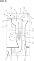
- a battery cooling air discharge device shown in Figures 1 and 2 is disposed between a battery 1 mounted under a vehicle V and a trim space 2 of the vehicle V, and is used to discharge battery cooling air, i.e., air for cooling the battery 1.
- the discharge device shown in the drawings is disposed on a floor panel P of the vehicle V between a front seat FS and a rear seat RS of the vehicle V. Note that Figures 1 and 2 omit interior materials forming the floor of the vehicle cabin.
- the battery 1 is housed in a case, not shown, and is cooled by the airflow from a fan 3, the battery cooling air being discharged through an exhaust port provided in the case.
- the trim space 2 shown in the drawings is formed under a rear kicking trim KT of the vehicle V.
- a drafter 4 that moves exhaust to the outside of the vehicle is shown in the trim space 2 for the sake of convenience.
- the trim space 2 communicates with a side trim space in the trunk space at the rear of the vehicle, and the drafter 4 is disposed in this side trim space.
- the discharge device is provided with an exhaust duct 10 that extends in the lateral direction of the vehicle V from the battery 1 to the trim space 2.
- the exhaust duct 10 is provided with a partition 11 that extends in the direction of the exhaust, and a forward flow path 12F and a rear flow path 12R divided toward the front and rear of the vehicle V by the partition 11, the rear flow path 12R having a cross-sectional area that is smaller than the cross-sectional area of the front flow path 12F.
- the structure of the partition 11, which is configured as a wall section integrally formed within the exhaust duct 10, is not particularly limited as long as said partition separates the front and rear flow paths 12F and 12R. Further, there is a merging area S of the front and rear flow paths 12F, 12R at the outlet side of the exhaust duct 10.
- the exhaust duct 10 shown in the illustrated example is provided with a connecting flow path pipe 13 that is connected to the exhaust port of the battery 1 and extends towards the rear of the vehicle (downward in the cross-sectional view), and a main flow path pipe 14 that turns at approximately a right angle from the connecting flow path pipe 13 and extends in the lateral direction of the vehicle.
- the partition 11 Inside the main flow path pipe 14, the partition 11, the front flow path 12F, the rear flow path 12R, and the converging region S described above are formed in the exhaust duct 10 along the longitudinal direction thereof, and an exhaust port 15 is provided at the terminal end, which opens into the trim space 2.
- the exhaust duct 10 has a guide wall 16, in which the merging area S side is a concave curved surface, at the outlet of the front flow path 12F.
- This guide wall 16 is formed continuously with a wall section 17 of the main flow path pipe 14 on the side toward the front of the vehicle in the plan view shown in Figure 1 , forming an approximately semicircular shape and reaching a front end 15F of the exhaust port 15.
- a wall section 18 of the main flow path pipe 14 on the side towards the rear of the vehicle is continuous with the connecting flow path pipe 13 and reaches a rear end 15R of the exhaust port 15.
- the exhaust port 15 is shaped such that the front end 15F on the guide wall 16 side projects further into the trim space 2 than the rear end 15R.
- the front flow path 12F may have a shape with a cross-sectional area that gradually expands in the direction of the exhaust.
- the cross-sectional area is caused to gradually expand by a slight inclination of the wall section 17 of the exhaust duct 10 on the side towards the front of the vehicle in the longitudinal direction of the partition 11.
- the main flow path pipe 14 of the exhaust duct 10 is a flat rectangular tube having an overall uniform thickness (height).
- the battery cooling air discharge device discharges the battery cooling air through the exhaust duct 10 into the trim space 2.
- the exhaust duct 10 is such that the cross-sectional area of the rear flow path 12R divided by the partition 11 is smaller than the cross-sectional area of the front flow path 12F, so that the velocity of air A1 flowing through the rear flow path 12R increases as the pressure decreases.
- the exhaust duct 10 draws air A2 passing through the front flow path 12F by means of the negative pressure of the air A1 passing through the rear flow path 12R in the merging area S on the outlet side, and releases both the air A1 and A2 into the trim space 2.
- the above-described battery cooling air discharge device can prevent the accumulation of heat downstream, e.g., near the seatbelt anchors, by actively forming an exhaust flow toward the rear of the vehicle within the trim space 2.
- the exhaust duct 10 is located under the interior materials near the footwell of the rear seat RS, but the partition 11 functions as reinforcement to prevent deformation of the exhaust duct 10.
- the exhaust duct 10 has the guide wall 16 in which the merging area S side is a convex curved surface at the outlet of the front flow path 12F.As a result, in the above-described discharge device, the air A2 that has passed through the front flow path 12F is diffused in the merging area S and rectified by traveling along the guide wall 16, and, coupled with the suction due to the negative pressure of the air A1 passing through the rear flow path 12R, can smoothly form the airflow A3 towards the rear of the vehicle.
- the battery cooling air discharge device has a shape in which the cross-sectional area of the front flow path 12F gradually expands in the direction of the exhaust, thereby gradually decreasing the speed of the air A2 flowing to the front flow path 12F, which can suppress the air blowing noise.
- the above-described exhaust device can increase the suction effect of the air A1 passing through the rear flow path 12R by increasing the pressure differential relative to the air A1 flowing through the rear flow path 12R.
- the trim space 2 is formed on the underside of the rear kicking trim KT of the vehicle V.
- the above-mentioned discharge device can thereby prevent air from flowing toward the front of the vehicle, e.g., prevent air leakage through the seatbelt holes in the center pillar, and since the trim space 2 is used as a duct, the exhaust duct 10 can be made smaller, lighter in weight, and lower in cost.
- the trim space 2 communicates with the drafter 4 located at the rear of the vehicle V, allowing the smooth discharge of the battery cooling air to the outside of the vehicle by utilizing the interior space of the vehicle V as a flow path.
- the configuration of the battery cooling air discharge device according to the present invention is not limited to the foregoing embodiment and may be modified as deemed suitable without departing from the essence of the present invention.
Landscapes
- Engineering & Computer Science (AREA)
- Chemical & Material Sciences (AREA)
- Chemical Kinetics & Catalysis (AREA)
- Electrochemistry (AREA)
- General Chemical & Material Sciences (AREA)
- Combustion & Propulsion (AREA)
- Transportation (AREA)
- Mechanical Engineering (AREA)
- Manufacturing & Machinery (AREA)
- Cooling, Air Intake And Gas Exhaust, And Fuel Tank Arrangements In Propulsion Units (AREA)
- Secondary Cells (AREA)
Applications Claiming Priority (1)
| Application Number | Priority Date | Filing Date | Title |
|---|---|---|---|
| PCT/JP2022/008315 WO2023162230A1 (ja) | 2022-02-28 | 2022-02-28 | バッテリ冷却風の排出装置 |
Publications (2)
| Publication Number | Publication Date |
|---|---|
| EP4488093A1 true EP4488093A1 (de) | 2025-01-08 |
| EP4488093A4 EP4488093A4 (de) | 2025-04-23 |
Family
ID=87765254
Family Applications (1)
| Application Number | Title | Priority Date | Filing Date |
|---|---|---|---|
| EP22928756.0A Withdrawn EP4488093A4 (de) | 2022-02-28 | 2022-02-28 | Entladungsvorrichtung für batteriekühlluft |
Country Status (5)
| Country | Link |
|---|---|
| US (1) | US20250178427A1 (de) |
| EP (1) | EP4488093A4 (de) |
| JP (1) | JP7755240B2 (de) |
| CN (1) | CN118786044A (de) |
| WO (1) | WO2023162230A1 (de) |
Families Citing this family (1)
| Publication number | Priority date | Publication date | Assignee | Title |
|---|---|---|---|---|
| WO2026047826A1 (ja) * | 2024-08-26 | 2026-03-05 | 日産自動車株式会社 | バッテリを冷却するファンの排気構造 |
Family Cites Families (8)
| Publication number | Priority date | Publication date | Assignee | Title |
|---|---|---|---|---|
| JP2006141153A (ja) * | 2004-11-12 | 2006-06-01 | Nissan Motor Co Ltd | バッテリ冷却装置 |
| JP4390802B2 (ja) * | 2006-12-15 | 2009-12-24 | トヨタ自動車株式会社 | 車載バッテリ冷却構造 |
| JP4780050B2 (ja) * | 2007-07-04 | 2011-09-28 | トヨタ自動車株式会社 | バッテリの冷却構造 |
| US9302573B2 (en) * | 2013-08-30 | 2016-04-05 | Ford Global Technologies, Llc | Duct for high voltage battery air cooling exhaust and recirculation |
| JP6244392B2 (ja) * | 2016-03-17 | 2017-12-06 | 本田技研工業株式会社 | 車両 |
| JP6668906B2 (ja) | 2016-04-13 | 2020-03-18 | 日産自動車株式会社 | バッテリ冷却風の排出構造 |
| JP6442450B2 (ja) * | 2016-08-24 | 2018-12-19 | 本田技研工業株式会社 | 車両 |
| JP7038155B2 (ja) * | 2020-03-04 | 2022-03-17 | 本田技研工業株式会社 | 電動車両 |
-
2022
- 2022-02-28 WO PCT/JP2022/008315 patent/WO2023162230A1/ja not_active Ceased
- 2022-02-28 US US18/841,747 patent/US20250178427A1/en active Pending
- 2022-02-28 JP JP2024502750A patent/JP7755240B2/ja active Active
- 2022-02-28 CN CN202280092594.6A patent/CN118786044A/zh active Pending
- 2022-02-28 EP EP22928756.0A patent/EP4488093A4/de not_active Withdrawn
Also Published As
| Publication number | Publication date |
|---|---|
| WO2023162230A1 (ja) | 2023-08-31 |
| JPWO2023162230A1 (de) | 2023-08-31 |
| US20250178427A1 (en) | 2025-06-05 |
| JP7755240B2 (ja) | 2025-10-16 |
| EP4488093A4 (de) | 2025-04-23 |
| CN118786044A (zh) | 2024-10-15 |
Similar Documents
| Publication | Publication Date | Title |
|---|---|---|
| CN102991340A (zh) | 用于机动车辆的冷却装置 | |
| EP4488093A1 (de) | Entladungsvorrichtung für batteriekühlluft | |
| US20250115311A1 (en) | Vehicle aerodynamics | |
| US20090036047A1 (en) | Recirculation air flow arrangement for vehicle hvac system | |
| CN101726079A (zh) | 车用空调的出风口构造 | |
| CN104943639B (zh) | 横梁 | |
| JP2019093843A (ja) | 車両用シート | |
| US20190176910A1 (en) | Air directing apparatus for a motor vehicle | |
| EP2788248B1 (de) | Fluidsteuerungsvorrichtung | |
| CN108883796A (zh) | 车辆整流装置 | |
| CN106043336A (zh) | 具有通入车辆表面上的空气通道的车辆 | |
| US10864951B2 (en) | Air-directing device for a motor-vehicle body, and motor-vehicle body | |
| US20210101442A1 (en) | Vehicle air conditioning duct | |
| US20130252530A1 (en) | Air distribution arrangement for use with vehicle hvac system and method of distributing air | |
| JP7600975B2 (ja) | 車両用空調装置 | |
| JP7480471B2 (ja) | 車両用サーキュレータ | |
| JP6415189B2 (ja) | 風向制御構造 | |
| US11597259B2 (en) | Ionized air delivery system | |
| JPH0635853Y2 (ja) | 車両用圧力緩和装置 | |
| US2807201A (en) | Vehicle body with built-in ventilation system | |
| KR101958704B1 (ko) | 자동차의 주행 안전장치 | |
| JP7748626B2 (ja) | 車両用送風構造 | |
| JPS625368Y2 (de) | ||
| CN110385964A (zh) | 双空调温控装置及车辆 | |
| US20250262915A1 (en) | System for Supplying an Air Flow to an Air Diffuser and Air Diffuser System for a Vehicle |
Legal Events
| Date | Code | Title | Description |
|---|---|---|---|
| STAA | Information on the status of an ep patent application or granted ep patent |
Free format text: STATUS: THE INTERNATIONAL PUBLICATION HAS BEEN MADE |
|
| PUAI | Public reference made under article 153(3) epc to a published international application that has entered the european phase |
Free format text: ORIGINAL CODE: 0009012 |
|
| STAA | Information on the status of an ep patent application or granted ep patent |
Free format text: STATUS: REQUEST FOR EXAMINATION WAS MADE |
|
| 17P | Request for examination filed |
Effective date: 20240925 |
|
| AK | Designated contracting states |
Kind code of ref document: A1 Designated state(s): AL AT BE BG CH CY CZ DE DK EE ES FI FR GB GR HR HU IE IS IT LI LT LU LV MC MK MT NL NO PL PT RO RS SE SI SK SM TR |
|
| A4 | Supplementary search report drawn up and despatched |
Effective date: 20250324 |
|
| RIC1 | Information provided on ipc code assigned before grant |
Ipc: H01M 10/6556 20140101ALI20250318BHEP Ipc: B60K 1/04 20190101ALI20250318BHEP Ipc: B60K 11/06 20060101AFI20250318BHEP |
|
| DAV | Request for validation of the european patent (deleted) | ||
| DAX | Request for extension of the european patent (deleted) | ||
| STAA | Information on the status of an ep patent application or granted ep patent |
Free format text: STATUS: THE APPLICATION IS DEEMED TO BE WITHDRAWN |
|
| 18D | Application deemed to be withdrawn |
Effective date: 20251011 |