EP4488006A2 - Tragbares elektrisch angetriebenes abschaltwerkzeug mit rückschlagabschwächungsfunktion - Google Patents
Tragbares elektrisch angetriebenes abschaltwerkzeug mit rückschlagabschwächungsfunktion Download PDFInfo
- Publication number
- EP4488006A2 EP4488006A2 EP24214457.4A EP24214457A EP4488006A2 EP 4488006 A2 EP4488006 A2 EP 4488006A2 EP 24214457 A EP24214457 A EP 24214457A EP 4488006 A2 EP4488006 A2 EP 4488006A2
- Authority
- EP
- European Patent Office
- Prior art keywords
- tool
- electric motor
- control unit
- cut
- kickback
- Prior art date
- Legal status (The legal status is an assumption and is not a legal conclusion. Google has not performed a legal analysis and makes no representation as to the accuracy of the status listed.)
- Pending
Links
Images


Classifications
-
- B—PERFORMING OPERATIONS; TRANSPORTING
- B28—WORKING CEMENT, CLAY, OR STONE
- B28D—WORKING STONE OR STONE-LIKE MATERIALS
- B28D7/00—Accessories specially adapted for use with machines or devices of the preceding groups
- B28D7/005—Devices for the automatic drive or the program control of the machines
-
- B—PERFORMING OPERATIONS; TRANSPORTING
- B25—HAND TOOLS; PORTABLE POWER-DRIVEN TOOLS; MANIPULATORS
- B25F—COMBINATION OR MULTI-PURPOSE TOOLS NOT OTHERWISE PROVIDED FOR; DETAILS OR COMPONENTS OF PORTABLE POWER-DRIVEN TOOLS NOT PARTICULARLY RELATED TO THE OPERATIONS PERFORMED AND NOT OTHERWISE PROVIDED FOR
- B25F5/00—Details or components of portable power-driven tools not particularly related to the operations performed and not otherwise provided for
-
- B—PERFORMING OPERATIONS; TRANSPORTING
- B28—WORKING CEMENT, CLAY, OR STONE
- B28D—WORKING STONE OR STONE-LIKE MATERIALS
- B28D1/00—Working stone or stone-like materials, e.g. brick, concrete or glass, not provided for elsewhere; Machines, devices, tools therefor
- B28D1/02—Working stone or stone-like materials, e.g. brick, concrete or glass, not provided for elsewhere; Machines, devices, tools therefor by sawing
- B28D1/04—Working stone or stone-like materials, e.g. brick, concrete or glass, not provided for elsewhere; Machines, devices, tools therefor by sawing with circular or cylindrical saw-blades or saw-discs
-
- H—ELECTRICITY
- H02—GENERATION; CONVERSION OR DISTRIBUTION OF ELECTRIC POWER
- H02H—EMERGENCY PROTECTIVE CIRCUIT ARRANGEMENTS
- H02H7/00—Emergency protective circuit arrangements specially adapted for specific types of electric machines or apparatus or for sectionalised protection of cable or line systems, and effecting automatic switching in the event of an undesired change from normal working conditions
- H02H7/08—Emergency protective circuit arrangements specially adapted for specific types of electric machines or apparatus or for sectionalised protection of cable or line systems, and effecting automatic switching in the event of an undesired change from normal working conditions for dynamo-electric motors
- H02H7/085—Emergency protective circuit arrangements specially adapted for specific types of electric machines or apparatus or for sectionalised protection of cable or line systems, and effecting automatic switching in the event of an undesired change from normal working conditions for dynamo-electric motors against excessive load
- H02H7/0854—Emergency protective circuit arrangements specially adapted for specific types of electric machines or apparatus or for sectionalised protection of cable or line systems, and effecting automatic switching in the event of an undesired change from normal working conditions for dynamo-electric motors against excessive load responsive to rate of change of current, couple or speed, e.g. anti-kickback protection
-
- H—ELECTRICITY
- H02—GENERATION; CONVERSION OR DISTRIBUTION OF ELECTRIC POWER
- H02K—DYNAMO-ELECTRIC MACHINES
- H02K7/00—Arrangements for handling mechanical energy structurally associated with dynamo-electric machines, e.g. structural association with mechanical driving motors or auxiliary dynamo-electric machines
- H02K7/14—Structural association with mechanical loads, e.g. with hand-held machine tools or fans
- H02K7/145—Hand-held machine tool
-
- H—ELECTRICITY
- H02—GENERATION; CONVERSION OR DISTRIBUTION OF ELECTRIC POWER
- H02P—CONTROL OR REGULATION OF ELECTRIC MOTORS, ELECTRIC GENERATORS OR DYNAMO-ELECTRIC CONVERTERS; CONTROLLING TRANSFORMERS, REACTORS OR CHOKE COILS
- H02P21/00—Arrangements or methods for the control of electric machines by vector control, e.g. by control of field orientation
- H02P21/06—Rotor flux based control involving the use of rotor position or rotor speed sensors
-
- H—ELECTRICITY
- H02—GENERATION; CONVERSION OR DISTRIBUTION OF ELECTRIC POWER
- H02P—CONTROL OR REGULATION OF ELECTRIC MOTORS, ELECTRIC GENERATORS OR DYNAMO-ELECTRIC CONVERTERS; CONTROLLING TRANSFORMERS, REACTORS OR CHOKE COILS
- H02P21/00—Arrangements or methods for the control of electric machines by vector control, e.g. by control of field orientation
- H02P21/14—Estimation or adaptation of machine parameters, e.g. flux, current or voltage
- H02P21/141—Flux estimation
-
- H—ELECTRICITY
- H02—GENERATION; CONVERSION OR DISTRIBUTION OF ELECTRIC POWER
- H02P—CONTROL OR REGULATION OF ELECTRIC MOTORS, ELECTRIC GENERATORS OR DYNAMO-ELECTRIC CONVERTERS; CONTROLLING TRANSFORMERS, REACTORS OR CHOKE COILS
- H02P21/00—Arrangements or methods for the control of electric machines by vector control, e.g. by control of field orientation
- H02P21/14—Estimation or adaptation of machine parameters, e.g. flux, current or voltage
- H02P21/143—Inertia or moment of inertia estimation
-
- H—ELECTRICITY
- H02—GENERATION; CONVERSION OR DISTRIBUTION OF ELECTRIC POWER
- H02P—CONTROL OR REGULATION OF ELECTRIC MOTORS, ELECTRIC GENERATORS OR DYNAMO-ELECTRIC CONVERTERS; CONTROLLING TRANSFORMERS, REACTORS OR CHOKE COILS
- H02P21/00—Arrangements or methods for the control of electric machines by vector control, e.g. by control of field orientation
- H02P21/14—Estimation or adaptation of machine parameters, e.g. flux, current or voltage
- H02P21/18—Estimation of position or speed
-
- H—ELECTRICITY
- H02—GENERATION; CONVERSION OR DISTRIBUTION OF ELECTRIC POWER
- H02P—CONTROL OR REGULATION OF ELECTRIC MOTORS, ELECTRIC GENERATORS OR DYNAMO-ELECTRIC CONVERTERS; CONTROLLING TRANSFORMERS, REACTORS OR CHOKE COILS
- H02P23/00—Arrangements or methods for the control of AC motors characterised by a control method other than vector control
- H02P23/14—Estimation or adaptation of motor parameters, e.g. rotor time constant, flux, speed, current or voltage
-
- H—ELECTRICITY
- H02—GENERATION; CONVERSION OR DISTRIBUTION OF ELECTRIC POWER
- H02P—CONTROL OR REGULATION OF ELECTRIC MOTORS, ELECTRIC GENERATORS OR DYNAMO-ELECTRIC CONVERTERS; CONTROLLING TRANSFORMERS, REACTORS OR CHOKE COILS
- H02P23/00—Arrangements or methods for the control of AC motors characterised by a control method other than vector control
- H02P23/20—Controlling the acceleration or deceleration
-
- H—ELECTRICITY
- H02—GENERATION; CONVERSION OR DISTRIBUTION OF ELECTRIC POWER
- H02P—CONTROL OR REGULATION OF ELECTRIC MOTORS, ELECTRIC GENERATORS OR DYNAMO-ELECTRIC CONVERTERS; CONTROLLING TRANSFORMERS, REACTORS OR CHOKE COILS
- H02P29/00—Arrangements for regulating or controlling electric motors, appropriate for both AC and DC motors
- H02P29/02—Providing protection against overload without automatic interruption of supply
- H02P29/024—Detecting a fault condition, e.g. short circuit, locked rotor, open circuit or loss of load
-
- H—ELECTRICITY
- H02—GENERATION; CONVERSION OR DISTRIBUTION OF ELECTRIC POWER
- H02P—CONTROL OR REGULATION OF ELECTRIC MOTORS, ELECTRIC GENERATORS OR DYNAMO-ELECTRIC CONVERTERS; CONTROLLING TRANSFORMERS, REACTORS OR CHOKE COILS
- H02P3/00—Arrangements for stopping or slowing electric motors, generators, or dynamo-electric converters
- H02P3/06—Arrangements for stopping or slowing electric motors, generators, or dynamo-electric converters for stopping or slowing an individual dynamo-electric motor or dynamo-electric converter
-
- H—ELECTRICITY
- H02—GENERATION; CONVERSION OR DISTRIBUTION OF ELECTRIC POWER
- H02P—CONTROL OR REGULATION OF ELECTRIC MOTORS, ELECTRIC GENERATORS OR DYNAMO-ELECTRIC CONVERTERS; CONTROLLING TRANSFORMERS, REACTORS OR CHOKE COILS
- H02P3/00—Arrangements for stopping or slowing electric motors, generators, or dynamo-electric converters
- H02P3/06—Arrangements for stopping or slowing electric motors, generators, or dynamo-electric converters for stopping or slowing an individual dynamo-electric motor or dynamo-electric converter
- H02P3/18—Arrangements for stopping or slowing electric motors, generators, or dynamo-electric converters for stopping or slowing an individual dynamo-electric motor or dynamo-electric converter for stopping or slowing an AC motor
-
- H—ELECTRICITY
- H02—GENERATION; CONVERSION OR DISTRIBUTION OF ELECTRIC POWER
- H02P—CONTROL OR REGULATION OF ELECTRIC MOTORS, ELECTRIC GENERATORS OR DYNAMO-ELECTRIC CONVERTERS; CONTROLLING TRANSFORMERS, REACTORS OR CHOKE COILS
- H02P3/00—Arrangements for stopping or slowing electric motors, generators, or dynamo-electric converters
- H02P3/06—Arrangements for stopping or slowing electric motors, generators, or dynamo-electric converters for stopping or slowing an individual dynamo-electric motor or dynamo-electric converter
- H02P3/18—Arrangements for stopping or slowing electric motors, generators, or dynamo-electric converters for stopping or slowing an individual dynamo-electric motor or dynamo-electric converter for stopping or slowing an AC motor
- H02P3/20—Arrangements for stopping or slowing electric motors, generators, or dynamo-electric converters for stopping or slowing an individual dynamo-electric motor or dynamo-electric converter for stopping or slowing an AC motor by reversal of phase sequence of connections to the motor
-
- H—ELECTRICITY
- H02—GENERATION; CONVERSION OR DISTRIBUTION OF ELECTRIC POWER
- H02P—CONTROL OR REGULATION OF ELECTRIC MOTORS, ELECTRIC GENERATORS OR DYNAMO-ELECTRIC CONVERTERS; CONTROLLING TRANSFORMERS, REACTORS OR CHOKE COILS
- H02P3/00—Arrangements for stopping or slowing electric motors, generators, or dynamo-electric converters
- H02P3/06—Arrangements for stopping or slowing electric motors, generators, or dynamo-electric converters for stopping or slowing an individual dynamo-electric motor or dynamo-electric converter
- H02P3/18—Arrangements for stopping or slowing electric motors, generators, or dynamo-electric converters for stopping or slowing an individual dynamo-electric motor or dynamo-electric converter for stopping or slowing an AC motor
- H02P3/22—Arrangements for stopping or slowing electric motors, generators, or dynamo-electric converters for stopping or slowing an individual dynamo-electric motor or dynamo-electric converter for stopping or slowing an AC motor by short-circuit or resistive braking
-
- H—ELECTRICITY
- H02—GENERATION; CONVERSION OR DISTRIBUTION OF ELECTRIC POWER
- H02P—CONTROL OR REGULATION OF ELECTRIC MOTORS, ELECTRIC GENERATORS OR DYNAMO-ELECTRIC CONVERTERS; CONTROLLING TRANSFORMERS, REACTORS OR CHOKE COILS
- H02P6/00—Arrangements for controlling synchronous motors or other dynamo-electric motors using electronic commutation dependent on the rotor position; Electronic commutators therefor
- H02P6/08—Arrangements for controlling the speed or torque of a single motor
-
- H—ELECTRICITY
- H02—GENERATION; CONVERSION OR DISTRIBUTION OF ELECTRIC POWER
- H02P—CONTROL OR REGULATION OF ELECTRIC MOTORS, ELECTRIC GENERATORS OR DYNAMO-ELECTRIC CONVERTERS; CONTROLLING TRANSFORMERS, REACTORS OR CHOKE COILS
- H02P6/00—Arrangements for controlling synchronous motors or other dynamo-electric motors using electronic commutation dependent on the rotor position; Electronic commutators therefor
- H02P6/14—Electronic commutators
- H02P6/16—Circuit arrangements for detecting position
- H02P6/18—Circuit arrangements for detecting position without separate position detecting elements
- H02P6/182—Circuit arrangements for detecting position without separate position detecting elements using back-emf in windings
-
- B—PERFORMING OPERATIONS; TRANSPORTING
- B27—WORKING OR PRESERVING WOOD OR SIMILAR MATERIAL; NAILING OR STAPLING MACHINES IN GENERAL
- B27G—ACCESSORY MACHINES OR APPARATUS FOR WORKING WOOD OR SIMILAR MATERIALS; TOOLS FOR WORKING WOOD OR SIMILAR MATERIALS; SAFETY DEVICES FOR WOOD WORKING MACHINES OR TOOLS
- B27G19/00—Safety guards or devices specially adapted for wood saws; Auxiliary devices facilitating proper operation of wood saws
- B27G19/02—Safety guards or devices specially adapted for wood saws; Auxiliary devices facilitating proper operation of wood saws for circular saws
- B27G19/04—Safety guards or devices specially adapted for wood saws; Auxiliary devices facilitating proper operation of wood saws for circular saws for manually-operated power-driven circular saws
Definitions
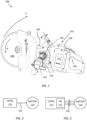
- the present disclosure relates to electrically powered hand-held cut-off tools for cutting concrete and stone, and in particular to kickback mitigation systems specifically tailored for such tools.
- Cut-off tools for processing hard materials such as concrete and stone require powerful motors which provide the necessary energy to process the hard materials.
- Electrically powered cut-off tools have recently been introduced. These machines comprise high performance batteries which power high torque electric motors. Some electrically powered cut-off tools are also powered via cable from electrical mains.
- the rotating cutting disc of the cut-off tool enters into locking contact with the object that is processed. Due to the large amounts of kinetic energy stored in the rapidly rotating cutting disc, the disc will be ejected from the object and the cut-off tool will move upwards and backwards towards the operator. This is referred to as a kickback condition, and it may cause severe injury to the operator. It is therefore highly desirable to avoid kickback events, and to mitigate the effects of a kickback event if it should anyway occur.
- US 10,675,694 B2 discloses a braking device able to quickly stop rotation of a rotating cutting disc with high inertia.
- a brake unit acts on a belt drive of a cut-off tool to efficiently brake a cutting disc from a state of high kinetic energy.
- US 8,413,340 B2 discloses a safety guard assembly for mitigating the harmful effects of a kickback event.
- the assembly includes a safety guard, a locking mechanism, and a weight.
- the locking mechanism quickly releases, and the weight forces the guard to swing rapidly down over the guard, thereby providing protection from the saw blade.
- US 2011/0007436 A1 discloses devices and methods for safety precaution in electrical tools.
- the disclosure comprises a sensor unit which is designed to generate a sensor signal based on, e.g., a motor current of an electric motor.
- the sensor signal can be used to trigger an electric braking action by the electric motor.
- EP 3 260 242 A1 and US 2020/0206887 A1 also relate to safety mechanisms for use with electrical powertools, which mechanisms comprise detection of a kickback event based on a change in rotation of a rotatable tool, followed by a braking action to slow down the tool.
- the braking operation is preferably a controlled braking operation which is regulated by the control unit. This controlled energy outtake from the electric motor reduces the risk for component damage and the like, while still providing efficient kickback mitigation.
- control unit is arranged to estimate a rotor angle of the electric motor based on a measured current over the control interface, and to obtain the data indicative of angular velocity as a difference of the rotor angle over time.
- Several methods for estimating rotor angle based on measurements of current over the control interface between control unit and electric motor are known. These methods advantageously do not require external sensors for measuring rotor angle.
- the control unit can be arranged to determine an angular position of a rotor of the electric motor based on data indicative of a rotor flux angle of the electric motor, and to obtain the data indicative of angular velocity as a difference of the rotor angular position over time.
- the entire kickback mitigation system disclosed herein can be integrated in its entirety in the control unit and electric motor assembly, which is an advantage.
- there is no need for advanced braking devices such as that disclosed in US 10,675,694 B2 .
- the hand-held electrically powered cut-off tool comprises an energy dissipating module configured to dissipate energy from the electric motor during the electromagnetic braking in a controlled manner.
- This energy dissipating module can be used by the control unit to perform braking in a controlled manner without risking, e.g., too high energy levels in the control unit circuitry, in the electric machine windings, or on the control interface.
- the energy dissipating module may, for instance, comprise any of a resistance, a super-capacitor, a cable connection to electrical mains and/or a battery configured with an energy absorption capacity.
- control unit is arranged to obtain the data indicative of the rotor flux angle of the electric motor based on a measured current over the control interface.
- This measurement of current is not associated with any significant implementation complexity in the control unit, which is an advantage.
- control unit may also be arranged to obtain the data indicative of a rotational velocity of the cutting disc at least in part from an external sensor, such as a Hall effect sensor or the like configured to measure rotations of the electric motor shaft.
- the external sensor can be used as an alternative to the current measurements on the control interface, or in combination with the current measurements on the control interface for increased reliability.
- control unit is arranged to process the data indicative of the angular velocity of the cutting disc by a first low-pass filter and by a second low-pass filter, where the first low-pass filter has a larger bandwidth compared to the second low-pass filter.
- the first low-pass filter is applied for kickback event detection, and the second low-pass filter is applied otherwise.
- the kickback event detection is preferably more rapid, which is why the higher bandwidth filter is used.
- a robust motor control is provided while at the same time a rapid kickback detection is enabled.
- the speed regulator function is bypassed when the control unit controls the electromagnetic braking during a kickback event to enable a more rapid braking operation.
- control unit is arranged to determine an angular acceleration associated with the electric motor, and to detect the kickback condition based on a comparison between the determined angular acceleration and a detection threshold.
- the control unit is arranged to detect the kickback condition also based on an angular velocity associated with the electric motor by conditioning kickback detection based on a minimum angular velocity.
- the detection threshold can be manually configurable or arranged to be automatically configured by the control unit, e.g., in dependence of tool inertia, or configured via wired or wireless link from a remote device, such as a smart phone or a remote server.
- a remote device such as a smart phone or a remote server.
- a remote operator can also configure the threshold, e.g., as part of a software upgrade, or in case an operator submits a request for reconfiguration of the threshold.
- the configuration can of course also be made from a wireless device, such as a smart phone or tablet device.
- control unit is arranged to obtain data indicative of a tool diameter or indicative of a tool inertia of the rotatable cutting disc, and to adjust the detection threshold based on the data indicative of tool diameter or tool inertia.
- kickback detection can be optimized to suit operation with a given tool.
- Some more heavy cutting discs may be associated with slightly different behavior in terms of decreased acceleration during kickback events compared to lighter cutting discs. If the tool inertia is approximately known, such differences can be compensated for in order to obtain a more reliable and accurate kickback detection mechanism.
- the control unit may for instance be arranged to obtain the data indicative of the tool diameter or tool inertia from manual input, or based on a calculated or an estimated tool inertia, wherein the tool inertia is arranged to be determined based on a current drawn by the electric motor during acceleration, e.g., from a standstill or low velocity condition.
- a robust mechanism for estimating tool inertia without external sensors or the like is provided. This mechanism can be applied to any cutting disc attached to the tool which is an advantage.
- the cut-off tool comprises a radio frequency identification (RFID) reader
- the control unit is arranged to obtain the data indicative of the tool diameter or tool inertia from an RFID device embedded into the cutting disc via the RFID reader. This way the tool diameter or tool inertia data is obtained directly from the cutting disc in a reliable manner. When the cutting disc is replaced by another cutting disc, the data is automatically updated.
- RFID radio frequency identification
- the cut-off tool comprises means for detecting tool identification data (ID) from an optically readable tag arranged on the tool or on a tool packaging associated with the tool, and to obtain the data indicative of the tool diameter or tool inertia based on the tool ID.
- ID tool identification data
- the cut-off tool may, for instance, be configured to contact a remote server or the like to obtain the required cutting disc data.
- the call to the remote server may comprise the tool ID obtained from the optically readable tag.
- the cut-off tool may comprise a radio transceiver, and the control unit can be arranged to obtain the data indicative of the tool diameter or tool inertia from the remote server via the radio transceiver.
- control unit is configured to control the electromagnetic braking of the electric motor by applying a configurable braking torque in dependence of a pre-determined time limit for braking the rotatable cutting disc. This means that the control unit does not always need to apply maximum braking force, and thereby spare components such as a braking resistor and other electrical components from increased wear due to hard use.
- the storage medium 1030 may also comprise persistent storage, which, for example, can be any single one or combination of magnetic memory, optical memory, solid state memory or even remotely mounted memory.
- the processing circuitry 1010 controls the general operation of the control unit 110, e.g., by sending data and control signals to the interface 1020 and the storage medium 1030, by receiving data and reports from the interface 1020, and by retrieving data and instructions from the storage medium 1030.
Landscapes
- Engineering & Computer Science (AREA)
- Power Engineering (AREA)
- Mechanical Engineering (AREA)
- Life Sciences & Earth Sciences (AREA)
- Mining & Mineral Resources (AREA)
- Wood Science & Technology (AREA)
- Forests & Forestry (AREA)
- Sawing (AREA)
- Processing Of Stones Or Stones Resemblance Materials (AREA)
- Control Of Ac Motors In General (AREA)
- Surgical Instruments (AREA)
- Finish Polishing, Edge Sharpening, And Grinding By Specific Grinding Devices (AREA)
Applications Claiming Priority (3)
| Application Number | Priority Date | Filing Date | Title |
|---|---|---|---|
| SE2051213A SE544811C2 (en) | 2020-10-19 | 2020-10-19 | A hand-held electrically powered cut-off tool with a kickback mitigation function |
| PCT/SE2021/050875 WO2022086380A1 (en) | 2020-10-19 | 2021-09-13 | A hand-held electrically powered cut-off tool with a kickback mitigation function |
| EP21883399.4A EP4229730A4 (de) | 2020-10-19 | 2021-09-13 | Tragbares elektrisch angetriebenes abschaltwerkzeug mit rückschlagabschwächungsfunktion |
Related Parent Applications (1)
| Application Number | Title | Priority Date | Filing Date |
|---|---|---|---|
| EP21883399.4A Division EP4229730A4 (de) | 2020-10-19 | 2021-09-13 | Tragbares elektrisch angetriebenes abschaltwerkzeug mit rückschlagabschwächungsfunktion |
Publications (2)
| Publication Number | Publication Date |
|---|---|
| EP4488006A2 true EP4488006A2 (de) | 2025-01-08 |
| EP4488006A3 EP4488006A3 (de) | 2025-03-26 |
Family
ID=81290874
Family Applications (3)
| Application Number | Title | Priority Date | Filing Date |
|---|---|---|---|
| EP24167960.4A Pending EP4369590A3 (de) | 2020-10-19 | 2021-09-13 | Tragbares elektrisch angetriebenes abschaltwerkzeug mit rückschlagabschwächungsfunktion |
| EP24214457.4A Pending EP4488006A3 (de) | 2020-10-19 | 2021-09-13 | Tragbares elektrisch angetriebenes abschaltwerkzeug mit rückschlagabschwächungsfunktion |
| EP21883399.4A Pending EP4229730A4 (de) | 2020-10-19 | 2021-09-13 | Tragbares elektrisch angetriebenes abschaltwerkzeug mit rückschlagabschwächungsfunktion |
Family Applications Before (1)
| Application Number | Title | Priority Date | Filing Date |
|---|---|---|---|
| EP24167960.4A Pending EP4369590A3 (de) | 2020-10-19 | 2021-09-13 | Tragbares elektrisch angetriebenes abschaltwerkzeug mit rückschlagabschwächungsfunktion |
Family Applications After (1)
| Application Number | Title | Priority Date | Filing Date |
|---|---|---|---|
| EP21883399.4A Pending EP4229730A4 (de) | 2020-10-19 | 2021-09-13 | Tragbares elektrisch angetriebenes abschaltwerkzeug mit rückschlagabschwächungsfunktion |
Country Status (5)
| Country | Link |
|---|---|
| US (2) | US12103201B2 (de) |
| EP (3) | EP4369590A3 (de) |
| CN (1) | CN116390833A (de) |
| AU (1) | AU2021363969A1 (de) |
| WO (2) | WO2022086383A1 (de) |
Families Citing this family (3)
| Publication number | Priority date | Publication date | Assignee | Title |
|---|---|---|---|---|
| AU2021363969A1 (en) * | 2020-10-19 | 2023-06-15 | Husqvarna Ab | A hand-held electrically powered cut-off tool with a kickback mitigation function |
| EP4302909A3 (de) * | 2022-06-13 | 2024-03-13 | Milwaukee Electric Tool Corporation | Trennsäge mit spritzschutz |
| EP4535648A1 (de) * | 2023-10-06 | 2025-04-09 | Hilti Aktiengesellschaft | Verfahren zum bremsen einer werkzeugmaschine und werkzeugmaschine |
Citations (8)
| Publication number | Priority date | Publication date | Assignee | Title |
|---|---|---|---|---|
| US7055620B2 (en) | 2001-04-06 | 2006-06-06 | Robert Bosch Gmbh | Hand-held machine tool |
| US20110007436A1 (en) | 2007-12-27 | 2011-01-13 | Robert Bosch Gmbh | Device and method for taking a safety precaution an in electrical tool |
| US8413340B2 (en) | 2009-11-04 | 2013-04-09 | John Michael Orlowski | Safety guard for power saw |
| EP3260242A1 (de) | 2016-06-20 | 2017-12-27 | Black & Decker Inc. | Elektrowerkzeug mit rückschlagsteuerungssystem |
| US10630223B2 (en) | 2015-12-28 | 2020-04-21 | Koki Holdings Co., Ltd. | Power tool |
| US10675694B2 (en) | 2014-05-24 | 2020-06-09 | Andreas Stihl Ag & Co. Kg | Handheld work apparatus |
| US10675747B2 (en) | 2014-11-20 | 2020-06-09 | Hilti Aktiengesellschaft | Control method for a hand-held power tool |
| US20200206887A1 (en) | 2017-07-24 | 2020-07-02 | Festool Gmbh | Power tool and method |
Family Cites Families (37)
| Publication number | Priority date | Publication date | Assignee | Title |
|---|---|---|---|---|
| US4267914A (en) | 1979-04-26 | 1981-05-19 | Black & Decker Inc. | Anti-kickback power tool control |
| US4249117A (en) * | 1979-05-01 | 1981-02-03 | Black And Decker, Inc. | Anti-kickback power tool control |
| DE3040516A1 (de) * | 1980-10-28 | 1982-05-27 | Fa. Andreas Stihl, 7050 Waiblingen | Sicherheitseinrichtung an einer motorsaege |
| JPH0866074A (ja) | 1994-08-19 | 1996-03-08 | Kokusan Denki Co Ltd | 電動機の停止制御方法及び装置 |
| DE10051775A1 (de) | 2000-10-19 | 2002-05-16 | Hilti Ag | Sicherheitsschaltung für drehendes Elektrohandwerkzeuggerät |
| GB0220951D0 (en) | 2002-09-11 | 2002-10-23 | Black & Decker Inc | Safety cut-off for power tool with rotating tool bit |
| DE102004004170A1 (de) | 2004-01-28 | 2005-08-18 | Robert Bosch Gmbh | Verfahren zur Abschaltung einer Elektrowerkzeugmaschine in einem Blockierfall und Elektrowerkzeugmaschine |
| US7410006B2 (en) | 2004-10-20 | 2008-08-12 | Black & Decker Inc. | Power tool anti-kickback system with rotational rate sensor |
| US8316958B2 (en) | 2006-07-13 | 2012-11-27 | Black & Decker Inc. | Control scheme for detecting and preventing torque conditions in a power tool |
| US20080021590A1 (en) | 2006-07-21 | 2008-01-24 | Vanko John C | Adaptive control scheme for detecting and preventing torque conditions in a power tool |
| US20090065225A1 (en) | 2007-09-07 | 2009-03-12 | Black & Decker Inc. | Switchable anti-lock control |
| JP5537122B2 (ja) | 2009-11-02 | 2014-07-02 | 株式会社マキタ | 電動工具 |
| DE102009046789A1 (de) | 2009-11-17 | 2011-05-19 | Robert Bosch Gmbh | Handwerkzeugmaschinenvorrichtung |
| JP5351752B2 (ja) | 2009-12-28 | 2013-11-27 | 株式会社マキタ | 電動工具 |
| DE102010027981A1 (de) | 2010-04-20 | 2011-10-20 | Robert Bosch Gmbh | Winkelschleifer |
| EP2465654B1 (de) | 2010-12-17 | 2017-07-26 | Robert Bosch GmbH | Kettensäge |
| US20140166323A1 (en) | 2012-09-16 | 2014-06-19 | J. Carl Cooper | Kickback Reduction for Power Tools and Machines |
| JP2014148006A (ja) | 2013-02-01 | 2014-08-21 | Makita Corp | 電動工具及び携帯用マルノコ |
| DE102013201708B4 (de) | 2013-02-01 | 2023-12-14 | Robert Bosch Gmbh | Elektrische Werkzeugmaschine und Verfahren zum Steuern der elektrischen Werkzeugmaschine |
| KR20150042038A (ko) * | 2013-10-10 | 2015-04-20 | 삼성전기주식회사 | 모터 보호 장치 및 그 방법, 그를 이용한 모터 제어 시스템 |
| JP6148609B2 (ja) | 2013-11-21 | 2017-06-14 | 株式会社マキタ | 電動工具 |
| EP2947765B1 (de) | 2014-05-20 | 2020-08-26 | Black & Decker Inc. | Elektronisches bremsen für einen universalmotor in einem elektrowerkzeug |
| US10144148B2 (en) | 2014-08-12 | 2018-12-04 | Robert Bosch Tool Corporation | System and method for kickback detection in a circular saw |
| US11571831B2 (en) | 2014-09-25 | 2023-02-07 | Robert Bosch Gmbh | System and method for kickback detection based on blade speed in a power tool |
| CN110281121B (zh) | 2014-11-28 | 2021-12-14 | 工机控股株式会社 | 电动工具 |
| US9833891B2 (en) | 2015-02-23 | 2017-12-05 | James Patterson | Anti-torqueing dynamic arresting mechanism |
| US11047528B2 (en) | 2016-02-12 | 2021-06-29 | Black & Decker Inc. | Electronic braking for a power tool having a brushless motor |
| JP6709129B2 (ja) | 2016-08-05 | 2020-06-10 | 株式会社マキタ | 電動工具 |
| JP6845656B2 (ja) | 2016-10-07 | 2021-03-24 | 株式会社マキタ | 電動工具 |
| JP2019051579A (ja) | 2017-09-19 | 2019-04-04 | 株式会社マキタ | 電動作業機 |
| DE102017216697A1 (de) | 2017-09-21 | 2019-03-21 | Robert Bosch Gmbh | Werkzeugmaschinenvorrichtung zu einer Steuerung und/oder Regelung zumindest einer Werkzeugmaschinenfunktion einer Werkzeugmaschine |
| EP3700713B1 (de) * | 2017-10-26 | 2023-07-12 | Milwaukee Electric Tool Corporation | Rückschlagsteuerungsverfahren für elektrowerkzeuge |
| CN109765048A (zh) | 2017-11-02 | 2019-05-17 | 南京德朔实业有限公司 | 电动工具以及电动工具反冲的检测方法 |
| JP7155514B2 (ja) * | 2017-12-15 | 2022-10-19 | マックス株式会社 | 電気機器 |
| WO2020108569A1 (zh) | 2018-11-28 | 2020-06-04 | 南京德朔实业有限公司 | 链锯、电动工具以及电动工具的控制方法 |
| EP3940910B1 (de) * | 2020-07-16 | 2025-06-25 | Inalfa Roof Systems Group B.V. | Verfahren und system zur hinderniserkennung |
| AU2021363969A1 (en) * | 2020-10-19 | 2023-06-15 | Husqvarna Ab | A hand-held electrically powered cut-off tool with a kickback mitigation function |
-
2021
- 2021-09-13 AU AU2021363969A patent/AU2021363969A1/en active Pending
- 2021-09-13 EP EP24167960.4A patent/EP4369590A3/de active Pending
- 2021-09-13 EP EP24214457.4A patent/EP4488006A3/de active Pending
- 2021-09-13 CN CN202180070805.1A patent/CN116390833A/zh active Pending
- 2021-09-13 US US18/032,260 patent/US12103201B2/en active Active
- 2021-09-13 EP EP21883399.4A patent/EP4229730A4/de active Pending
- 2021-09-20 WO PCT/SE2021/050903 patent/WO2022086383A1/en not_active Ceased
- 2021-09-20 WO PCT/SE2021/050902 patent/WO2022086382A1/en not_active Ceased
- 2021-09-20 US US18/032,240 patent/US12558814B2/en active Active
Patent Citations (8)
| Publication number | Priority date | Publication date | Assignee | Title |
|---|---|---|---|---|
| US7055620B2 (en) | 2001-04-06 | 2006-06-06 | Robert Bosch Gmbh | Hand-held machine tool |
| US20110007436A1 (en) | 2007-12-27 | 2011-01-13 | Robert Bosch Gmbh | Device and method for taking a safety precaution an in electrical tool |
| US8413340B2 (en) | 2009-11-04 | 2013-04-09 | John Michael Orlowski | Safety guard for power saw |
| US10675694B2 (en) | 2014-05-24 | 2020-06-09 | Andreas Stihl Ag & Co. Kg | Handheld work apparatus |
| US10675747B2 (en) | 2014-11-20 | 2020-06-09 | Hilti Aktiengesellschaft | Control method for a hand-held power tool |
| US10630223B2 (en) | 2015-12-28 | 2020-04-21 | Koki Holdings Co., Ltd. | Power tool |
| EP3260242A1 (de) | 2016-06-20 | 2017-12-27 | Black & Decker Inc. | Elektrowerkzeug mit rückschlagsteuerungssystem |
| US20200206887A1 (en) | 2017-07-24 | 2020-07-02 | Festool Gmbh | Power tool and method |
Non-Patent Citations (1)
| Title |
|---|
| AUSTIN HUGHESBILL DRURY: "Electric Motors and Drives", 2019, ELSEVIER |
Also Published As
| Publication number | Publication date |
|---|---|
| AU2021363969A1 (en) | 2023-06-15 |
| EP4229730A4 (de) | 2024-08-07 |
| CN116390833A (zh) | 2023-07-04 |
| EP4369590A2 (de) | 2024-05-15 |
| EP4229730A1 (de) | 2023-08-23 |
| US20230396056A1 (en) | 2023-12-07 |
| EP4369590A3 (de) | 2024-08-21 |
| WO2022086382A1 (en) | 2022-04-28 |
| AU2021363969A9 (en) | 2024-10-03 |
| EP4488006A3 (de) | 2025-03-26 |
| US12103201B2 (en) | 2024-10-01 |
| US20230390963A1 (en) | 2023-12-07 |
| US20230405875A1 (en) | 2023-12-21 |
| US12558814B2 (en) | 2026-02-24 |
| WO2022086383A1 (en) | 2022-04-28 |
Similar Documents
| Publication | Publication Date | Title |
|---|---|---|
| US12103201B2 (en) | Hand-held electrically powered cut-off tool with a kickback mitigation function | |
| US12151355B2 (en) | Fault detection methods for power tools | |
| JP4913294B2 (ja) | 安全クラッチを具える電動工具 | |
| EP3225361B1 (de) | Elektrowerkzeug | |
| US5584619A (en) | Method of and arrangement for preventing accidents during operation of a manually-operated machine tool with a rotatable toolbit | |
| EP2195920B1 (de) | Schutz und verfahren zum schutzen eines fahrstuhls | |
| RU2588971C2 (ru) | Угловая шлифовальная машина с датчиком скорости вращения для измерения вращения корпуса | |
| US6747427B1 (en) | Motor torque control to reduce possibility of centrifuge rotor accidents | |
| WO2022086380A1 (en) | A hand-held electrically powered cut-off tool with a kickback mitigation function | |
| US12629866B2 (en) | Hand-held electrically powered cut-off tool with a kickback mitigation function | |
| EP4305273A1 (de) | Zuführeinheit zum zuführen eines kernbohrmeissels in ein arbeitsobjekt | |
| EP3415348A1 (de) | Verbessertes verfahren und ausrüstung zum aufziehen von reifen auf felgen und zu deren entfernen davon | |
| CN107093974B (zh) | 电动机控制装置以及电动机控制方法 | |
| US6650075B2 (en) | Fan motor | |
| CN107872187B (zh) | 电动机控制装置 | |
| CN105121776B (zh) | 用于排空油井的方法以及用于实施所述方法的系统 | |
| JP7460749B2 (ja) | 制御装置及びプログラム | |
| JP4168952B2 (ja) | 遠心機 | |
| CN209860747U (zh) | 温度监控和保护电路 | |
| JP2017070203A (ja) | 少なくとも1つの交流モータを備えている装置 | |
| JPH1170496A (ja) | 食肉スライサー | |
| JP2005230750A (ja) | 遠心機 | |
| JPS5911275B2 (ja) | 電動機の過負荷停止装置 |
Legal Events
| Date | Code | Title | Description |
|---|---|---|---|
| PUAI | Public reference made under article 153(3) epc to a published international application that has entered the european phase |
Free format text: ORIGINAL CODE: 0009012 |
|
| STAA | Information on the status of an ep patent application or granted ep patent |
Free format text: STATUS: THE APPLICATION HAS BEEN PUBLISHED |
|
| AC | Divisional application: reference to earlier application |
Ref document number: 4229730 Country of ref document: EP Kind code of ref document: P |
|
| AK | Designated contracting states |
Kind code of ref document: A2 Designated state(s): AL AT BE BG CH CY CZ DE DK EE ES FI FR GB GR HR HU IE IS IT LI LT LU LV MC MK MT NL NO PL PT RO RS SE SI SK SM TR |
|
| REG | Reference to a national code |
Ref country code: DE Ref legal event code: R079 Free format text: PREVIOUS MAIN CLASS: B25F0005000000 Ipc: H02P0003060000 |
|
| PUAL | Search report despatched |
Free format text: ORIGINAL CODE: 0009013 |
|
| AK | Designated contracting states |
Kind code of ref document: A3 Designated state(s): AL AT BE BG CH CY CZ DE DK EE ES FI FR GB GR HR HU IE IS IT LI LT LU LV MC MK MT NL NO PL PT RO RS SE SI SK SM TR |
|
| RIC1 | Information provided on ipc code assigned before grant |
Ipc: B27G 19/04 20060101ALI20250218BHEP Ipc: B27G 19/02 20060101ALI20250218BHEP Ipc: B25F 5/00 20060101ALI20250218BHEP Ipc: H02H 7/085 20060101ALI20250218BHEP Ipc: H02P 23/20 20160101ALI20250218BHEP Ipc: H02P 29/02 20160101ALI20250218BHEP Ipc: H02P 23/14 20060101ALI20250218BHEP Ipc: H02P 21/18 20160101ALI20250218BHEP Ipc: H02P 21/14 20160101ALI20250218BHEP Ipc: H02P 21/06 20160101ALI20250218BHEP Ipc: H02P 6/18 20160101ALI20250218BHEP Ipc: H02P 6/08 20160101ALI20250218BHEP Ipc: H02P 3/22 20060101ALI20250218BHEP Ipc: H02P 3/20 20060101ALI20250218BHEP Ipc: H02P 3/18 20060101ALI20250218BHEP Ipc: H02P 3/06 20060101AFI20250218BHEP |
|
| STAA | Information on the status of an ep patent application or granted ep patent |
Free format text: STATUS: REQUEST FOR EXAMINATION WAS MADE |
|
| 17P | Request for examination filed |
Effective date: 20250911 |
|
| STAA | Information on the status of an ep patent application or granted ep patent |
Free format text: STATUS: EXAMINATION IS IN PROGRESS |
|
| 17Q | First examination report despatched |
Effective date: 20260309 |