EP4483708A1 - Rasenmäher - Google Patents
Rasenmäher Download PDFInfo
- Publication number
- EP4483708A1 EP4483708A1 EP23759077.3A EP23759077A EP4483708A1 EP 4483708 A1 EP4483708 A1 EP 4483708A1 EP 23759077 A EP23759077 A EP 23759077A EP 4483708 A1 EP4483708 A1 EP 4483708A1
- Authority
- EP
- European Patent Office
- Prior art keywords
- lawn
- connecting rod
- platform
- cutting deck
- mower
- Prior art date
- Legal status (The legal status is an assumption and is not a legal conclusion. Google has not performed a legal analysis and makes no representation as to the accuracy of the status listed.)
- Pending
Links
Images


Classifications
-
- A—HUMAN NECESSITIES
- A01—AGRICULTURE; FORESTRY; ANIMAL HUSBANDRY; HUNTING; TRAPPING; FISHING
- A01D—HARVESTING; MOWING
- A01D34/00—Mowers; Mowing apparatus of harvesters
- A01D34/01—Mowers; Mowing apparatus of harvesters characterised by features relating to the type of cutting apparatus
- A01D34/412—Mowers; Mowing apparatus of harvesters characterised by features relating to the type of cutting apparatus having rotating cutters
- A01D34/63—Mowers; Mowing apparatus of harvesters characterised by features relating to the type of cutting apparatus having rotating cutters having cutters rotating about a vertical axis
- A01D34/64—Mowers; Mowing apparatus of harvesters characterised by features relating to the type of cutting apparatus having rotating cutters having cutters rotating about a vertical axis mounted on a vehicle, e.g. a tractor, or drawn by an animal or a vehicle
- A01D34/66—Mowers; Mowing apparatus of harvesters characterised by features relating to the type of cutting apparatus having rotating cutters having cutters rotating about a vertical axis mounted on a vehicle, e.g. a tractor, or drawn by an animal or a vehicle with two or more cutters
- A01D34/661—Mounting means
-
- A—HUMAN NECESSITIES
- A01—AGRICULTURE; FORESTRY; ANIMAL HUSBANDRY; HUNTING; TRAPPING; FISHING
- A01D—HARVESTING; MOWING
- A01D34/00—Mowers; Mowing apparatus of harvesters
- A01D34/01—Mowers; Mowing apparatus of harvesters characterised by features relating to the type of cutting apparatus
- A01D34/412—Mowers; Mowing apparatus of harvesters characterised by features relating to the type of cutting apparatus having rotating cutters
- A01D34/63—Mowers; Mowing apparatus of harvesters characterised by features relating to the type of cutting apparatus having rotating cutters having cutters rotating about a vertical axis
- A01D34/71—Mowers; Mowing apparatus of harvesters characterised by features relating to the type of cutting apparatus having rotating cutters having cutters rotating about a vertical axis with means for discharging mown material
-
- A—HUMAN NECESSITIES
- A01—AGRICULTURE; FORESTRY; ANIMAL HUSBANDRY; HUNTING; TRAPPING; FISHING
- A01D—HARVESTING; MOWING
- A01D34/00—Mowers; Mowing apparatus of harvesters
- A01D34/01—Mowers; Mowing apparatus of harvesters characterised by features relating to the type of cutting apparatus
- A01D34/412—Mowers; Mowing apparatus of harvesters characterised by features relating to the type of cutting apparatus having rotating cutters
- A01D34/63—Mowers; Mowing apparatus of harvesters characterised by features relating to the type of cutting apparatus having rotating cutters having cutters rotating about a vertical axis
- A01D34/81—Casings; Housings
-
- A—HUMAN NECESSITIES
- A01—AGRICULTURE; FORESTRY; ANIMAL HUSBANDRY; HUNTING; TRAPPING; FISHING
- A01D—HARVESTING; MOWING
- A01D67/00—Undercarriages or frames specially adapted for harvesters or mowers; Mechanisms for adjusting the frame; Platforms
-
- A—HUMAN NECESSITIES
- A01—AGRICULTURE; FORESTRY; ANIMAL HUSBANDRY; HUNTING; TRAPPING; FISHING
- A01G—HORTICULTURE; CULTIVATION OF VEGETABLES, FLOWERS, RICE, FRUIT, VINES, HOPS OR SEAWEED; FORESTRY; WATERING
- A01G20/00—Cultivation of turf, lawn or the like; Apparatus or methods therefor
- A01G20/30—Apparatus for treating the lawn or grass surface
-
- B—PERFORMING OPERATIONS; TRANSPORTING
- B62—LAND VEHICLES FOR TRAVELLING OTHERWISE THAN ON RAILS
- B62D—MOTOR VEHICLES; TRAILERS
- B62D51/00—Motor vehicles characterised by the driver not being seated
- B62D51/02—Motor vehicles characterised by the driver not being seated the driver standing in the vehicle
Definitions
- the disclosure relates a technical field of power tools, especially relates to a mower.
- Mowers are mechanical tools used to mow lawns, vegetation, etc.
- the platform of the conventional mower can only be used under conditions where the lawn is relatively flat and there are fewer obstacles.
- the conventional structure is not sufficient to effectively reduce the up and down shock frequency of the driver, which will increase the difficulty of the driver's control of the machine, easily cause misoperation, and pose a safety hazard.
- the standing mower is not sufficient to effectively reduce the up and down shock frequency of the driver, the traditional platform assembly can no longer meet customers' requirements for standing mowers.
- the disclosure provides a mower to improve a problem that conventional mowers are not able to effectively reduce an up and down shock frequency of a driver when used in conditions where the lawn is uneven and there are many road obstacles, thereby increasing an operation difficulty of a machine to the driver, easily causing a misoperation, and posing a safety hazard.
- the disclosure further provides the mower.
- the mower includes a frame, a working assembly and a platform assembly.
- the working assembly is connected with the frame.
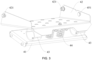
- the platform assembly is connected to the frame, and includes a supporting plate, a platform and a damper.
- the supporting plate is fixedly connected with the frame.
- a platform one side of the platform rotatably connected with the frame and located above the supporting plate;
- the damper is mounted on the supporting plate and located between the platform and the supporting plate.
- the damper includes at least a first damper and a second damper, and the first damper and the second damper are respectively mounted on two sides of the supporting plate.
- a distance L1 between an orthographic projection on the supporting plate of a rotation center of the platform rotatably connected with the frame and the damper is set between 180 mm and 200 mm.
- a plurality of mounting holes is arranged on one side of the platform, and the damper is mounted on different mounting holes through fixing components.
- the plurality of mounting holes is arranged in a straight line along a width direction of the supporting plate, and a maximum distance L2 between two of the plurality of mounting holes is set to 100 mm.
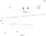
- a distance L3 between an orthographic projection on the supporting plate of the rotation center of the platform rotatably connected with the frame and the driver's center of gravity is set between 80 mm and 100 mm.
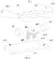
- the mower further includes a compression spring assembly, which is mounted between the platform and the supporting plate, and located between the first damper and the second damper.
- the compression spring assembly includes a pressing plate and a spring, a first end of the spring is fixedly connected with the pressing plate through a first bolt, and a second end of the spring is fixedly connected with the supporting plate through a second bolt.
- the spring includes at least a first spring and a second spring, and the first spring and the second spring are symmetrically arranged on two sides of the pressing plate with respect to a center line of the pressing plate.
- the mower further includes an elastic component, which is connected between the frame and the platform.
- a first end of the elastic component is fixedly mounted on the platform through a first limiting bolt
- a second end of the elastic component is fixedly mounted on the frame through a second limiting bolt
- the first limiting bolt is located on a side of the platform away from a rotation shaft of the platform.
- the mower further includes an operator presence switch, arranged on the platform assembly.
- the cutting deck baffle is rotatably mounted at the opening, and when the cutting deck baffle is located at the opening to close the opening, the mower is in a lawn crushing state;
- an angle between the cutting deck baffle and the lawn discharging plate is set between 150° and 185°.
- the disclosure proposes a mower to improve a problem that when a lawn is uneven and there are many obstacles, the mower with a traditional structure is not enough to effectively reduce an up and down shock frequency of a driver, which will increase a difficulty of the driver to control a machine and pose a safety hazard.
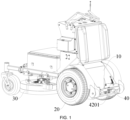
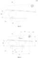
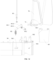
- the mower includes a frame 10, a driving wheel 20, a working assembly 30 and a platform assembly 40.
- two driving wheels 20 are arranged on the mower, mounted at two ends of a rear side of the frame 10, and used to drive the mower to walk.
- the driving wheel 20 may further be mounted at a front end or other position of the frame 10.
- the working assembly 30 is mounted at a bottom of the frame 10.
- the working assembly 30 may further be mounted at the front end, a rear end or a side of the frame 10, and the platform assembly 40 is connected to the rear side of the frame 10.
- the spring 442 includes at least a first spring and a second spring, and the first spring and the second spring are symmetrically arranged on two sides of the pressing plate 441 about a center line of the pressing plate 441.
- the center line is perpendicular to the rotation axis between the platform 42 and the frame 10 in space to ensure its structural stability.
- the compression spring assembly 44 may also play a shock-absorbing role, buffering an impact caused by bumps.
- a first end of the elastic component 45 is fixedly mounted on the platform 42 through a first limiting bolt 451, and a second end of the elastic component 45 is fixedly mounted on the frame 10 through a second limiting bolt 452, and the first limiting bolt 451 is located on a side of the platform 42 away from the rotation shaft.
- the platform 42 returns to its initial position under an action of the elastic component 45 when no external force is applied to the platform 42 to press downward.
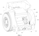
- a limiting component 4021 is further arranged on the frame 10, and the platform 42 is limited on the frame 10 through the limiting component 4201 to prevent the platform 42 from being pulled upward excessively under a tension of the elastic component 45.
- L1 is the distance between the orthographic projection on the supporting plate 41 of the rotation center of platform 42 rotatably connected with the frame 10 and the damper 43, and the distance L1 is, for example, set between 180 mm and 200 mm.
- L3 is the distance between the orthographic projection on the supporting plate 41 of the rotation center of platform 42 rotatably connected with the frame 10 and the driver's the center of gravity, and the distance L3 is, for example, set between 80 mm and 100 mm.
- the damper 43 is in a balanced state, and a height of the damper is H2, which means that H2 is a height parameter of the damper in the balanced state, and a compression distance ⁇ H of the damper 43 may be obtained to be H1-H2.
- the platform assembly 40 when the driver operates the mower and it is bumpy, the platform assembly 40 is in the state of the impact load limiting position.
- the damper in the platform assembly 40 may effectively consume kinetic energy generated by road bumps and reduce the up and down shock frequency of the driver when a standing mower is in a working state.
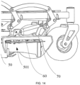
- a linkage adjustment is formed between a lawn discharging plate 70 and a cutting deck baffle 60 on the mower, so that the cutting deck baffle 60 may be switched on an operating deck without the driver getting off the mower, and the lawn discharging plate 70 works synchronously when the cutting deck baffle 60 is switched.
- the working assembly 30 includes a cutting deck 50, a cutting deck baffle 60, a lawn discharging plate 70 and a linkage adjustment mechanism 80.
- the driving wheel 20 is mounted at the bottom of the frame 10 to move the mower 100.
- the cutting deck 50 is connected on the frame 10.
- the cutting deck 50 is, for example, mounted at the bottom of the frame 10, and a cutting tool assembly is mounted in the cutting deck 50 for mowing.
- the cutting deck baffle 60 is used in conjunction with the cutting deck 50 when the mower 100 is crushing lawn.
- the lawn discharging plate 70 is used in conjunction with the cutting deck 50 when the mower 100 is discharging the lawn.
- the linkage adjustment mechanism 80 is used to adjust and switch the cutting deck baffle 60 and the lawn discharging plate 70 so that a linkage is achieved between the cutting deck baffle 60 and the lawn discharging plate 70.
- an opening 501 is arranged on one side of the cutting deck 50, and the cutting deck baffle 60 is rotatably mounted at the opening 501.
- the cutting deck baffle 60 is rotatably connected with the cutting deck 50 through at least two bolts, axes of the two bolts are located on a same straight line, and the straight line is a rotation axis between the cutting deck baffle 60 and the cutting deck 50.
- the lawn discharging plate 70 is also rotatably mounted on the cutting deck 50.
- a bracket 502 is fixedly mounted on the cutting deck 50 near the opening 501.
- the lawn discharging plate 70 is rotatably mounted together with the bracket 502 through a rotation shaft 71 of the lawn discharging plate, and the lawn discharging plate 70 is mounted on the rotation shaft 71 through an elastic cylindrical pin.
- the angle is, for example, set between 150° and 185°.
- a vertical height H between a rotation axis of the cutting deck baffle 60 and a rotation axis of the rotation shaft 71 of the lawn discharging plate is set between 35 mm and 45 mm.
- the vertical height H is set to 40 mm, for example, to avoid enabling an overall head height of the lawn discharging plate 70 too high and unable to adapt to the cutting deck 50, thereby affecting a lawn discharging performance.
- the linkage adjustment mechanism 80 is mounted on the mower 100, which is convenient for a linkage adjustment of the cutting deck baffle 60 and the lawn discharging plate 70.
- the linkage adjustment mechanism 80 includes a connecting rod mechanism 81, a reset tension spring 82, a pulling wire 83 and a handle assembly 84.
- the connecting rod mechanism 81, the reset tension spring 82, the pulling wire 83 and the handle assembly 84 are all located on a same side of the cutting deck baffle 60 and the lawn discharging plate 70.
- the connecting rod mechanism 81 is connected between the cutting deck baffle 60 and the lawn discharging plate 70.
- the cutting deck baffle 60 is flipped upward through the connecting rod mechanism 81, and at the same time the lawn discharging plate 70 is flipped downward, so that the lawn discharging plate 70 and the cutting deck baffle 60 reach a lawn discharging position synchronously.
- the mower 100 is in the lawn discharging state.
- the lawn discharging plate 70 and the cutting deck baffle 60 are both in an approximately horizontal or horizontal position, so as to be used in conjunction with the cutting deck 50.
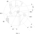
- the connecting rod mechanism 81 includes a first connecting rod 811, a second connecting rod 812 and a third connecting rod 813.
- the second connecting rod 812 is rotatably connected between the first connecting rod 811 and the third connecting rod 813, which means that a first end of the second connecting rod 812 is rotatably connected with the first connecting rod 811, and a second end of the second connecting rod 812 is rotatably connected with the third connecting rod 813.
- the first connecting rod 811 is connected with the rotation shaft 71 of the lawn discharging plate, and the third connecting rod 813 is fixedly connected with the cutting deck baffle 60.
- the third connecting rod 813 is located at one side of the cutting deck baffle 60 and is integrally formed with the cutting deck baffle 60 to ensure its structural strength.
- the first connecting rod 811 includes a first part 8111 and a second part 8112. There is an angle between the first part 8111 and the second part 8112. A first end of the second part 8112 is connected with the rotation shaft 71 of the lawn discharging plate, and a second end of the second part 8112 is connected with the second connecting rod 812.
- the connecting rod mechanism 81 can adjust positions of the cutting deck baffle 60 and the lawn discharging plate 70 to form a linkage structure between the cutting deck baffle 60 and the lawn discharging plate 70, so that the mower can switch between the lawn crushing state and the lawn discharging state.
- the first part 8111 and the second part 8112 are an integrally formed structure to ensure their structural strength.
- a first end of the reset tension spring 82 is connected with an outer side of the cutting deck 50, and a second end of the reset tension spring 82 is connected with the first connecting rod 811.
- a lifting eye structure 503 is fixedly mounted on the outer side of the cutting deck 50.
- a first end of the reset tension spring 82 is fixedly connected with the lifting eye structure 503, and a second end of the reset tension spring 82 is fixedly connected with an end of the first part 8111 away from the second part 8112.
- the cutting deck baffle 60 may be flipped downward to be matched with the opening 501 on the side of the cutting deck 50 to close the opening 501.
- the lawn discharging plate 70 is flipped upward, so that the mower 100 returns to the lawn crushing state.
- a length L4 of the second part 8112 of the first connecting rod 811 is set between 20 mm and 30 mm
- a length L5 of the second connecting rod 812 is set between 35 mm and 45 mm
- a length L3 of the third connecting rod 813 is set between 25 mm and 35 mm.
- the length L4 of the second part 8112 is set to 25 mm, for example, the length L5 of the second connecting rod 812 is set to 40 mm, and the length L6 of the third connecting rod 813 is set to 30 mm, for example, to ensure that the cutting deck baffle 60 and the lawn discharging plate 70 can be flipped to a suitable angle when flipping, so as to reach a specified position exactly, thereby realizing different functions.
- a first end of the pulling wire 83 is fixedly connected with the first part 8111
- a second end of the pulling wire 83 is connected with the handle assembly 84
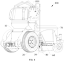
- the handle assembly 84 is mounted on a control base assembly 1001 of the mower 100.
- the handle assembly 84 is rotated, and a pulling force of the pulling wire 83 drives the first connecting rod 811 to rotate, so that the cutting deck baffle 60 and the lawn discharging plate 70 are flipped in a direction close to each other, and the mower 100 is switched to the lawn discharging state.
- the mower 100 is in the lawn discharging state as shown in FIG. 14 .
- the first connecting rod 811 loses the pulling force of the pulling wire 83, and under an elastic force of the reset tension spring 82, the cutting deck baffle 60 and the lawn discharging plate 70 are flipped away from each other, so that the mower 100 is switched to the lawn crushing state.
- the mower 100 is in the lawn discharging state as shown in FIG. 8 .
- a boss 841 is arranged on one side of the handle assembly 84 close to the control base assembly 1001, and a plurality of positioning holes 1002 are correspondingly arranged on a housing of the control base assembly 1001.
- the handle assembly 84 is matched with the different positioning holes 1002 through the boss 841 to limit the handle assembly 84 to different positions, thereby facilitating a switching and an adjustment between the cutting deck baffle 60 and the lawn discharging plate 70.
- the cutting deck baffle 60 is matched with the opening 501 on the side of the cutting deck 50 to close the opening 51, and at the same time enables the lawn discharging plate 70 to be in an open state.
- the mower 100 is in the lawn crushing state.
- there is an angle between the cutting deck baffle 60 and the lawn discharging plate 70 and the angle is set between 150° and 185°, for example, set to 160°.
- the handle assembly 84 is rotated, and the first connecting rod 811 is pulled by the pulling wire 83.
- an upward flipping angle of the cutting deck baffle 60 relative to a position of the cutting deck baffle 60 when the mower 100 in the lawn crushing state is set between 90° and 98°
- a downward flipping angle of the lawn discharging plate 70 relative to a position of the lawn discharging plate 70 of the mower 100 in the lawn crushing state is set between 65° and 96°.
- the cutting deck baffle 60 is flipped upward by 90°, for example, the lawn discharging plate 70 is flipped downward by 71°, so that the cutting deck baffle 60 and the lawn discharging plate 70 are both in a horizontal or approximately horizontal position, and the mower 100 is in the lawn discharging plate.
- the disclosure provides the mower, which reduces a number of components of the platform assembly and eliminates two rubber blocks that play a limiting role.
- the disclosure mounts the damper between the platform and the supporting plate, so that the entire platform assembly can provide a shock reduction functions during an operation of a standing mower. Compared with a performance of traditional platform assemblies under bumpy conditions, this platform assembly can provide a more effective shock reduction function, which brings customers a more perfect experience.
- the disclosure provides the mower.
- the lawn discharging plate and the cutting deck baffle are mounted on the cutting deck.
- the lawn discharging plate and the cutting deck baffle are linked and adjusted through the linkage adjustment mechanism, so that the cutting deck baffle can be switched on an operating deck without the driver getting off a mowing vehicle, and the lawn discharging plate work synchronously, which means that when the cutting deck baffle is not needed, the cutting deck baffle does not need to be removed, only the cutting deck baffle needs to be opened and the lawn discharging plate is lowered at the same time.
- the cutting deck baffle may be directly lowered and the lawn discharging plate may be raised at the same time.
- the disclosure does not use tools to disassemble the cutting deck baffle, and the cutting deck baffle and the lawn discharging plate are linked.
- the blocking plate is not working
- the lawn discharging plate is working.
- the cutting deck baffle is working.
Landscapes
- Life Sciences & Earth Sciences (AREA)
- Environmental Sciences (AREA)
- Engineering & Computer Science (AREA)
- Chemical & Material Sciences (AREA)
- Combustion & Propulsion (AREA)
- Transportation (AREA)
- Mechanical Engineering (AREA)
- Harvester Elements (AREA)
Applications Claiming Priority (3)
| Application Number | Priority Date | Filing Date | Title |
|---|---|---|---|
| CN202220376000.1U CN217445886U (zh) | 2022-02-23 | 2022-02-23 | 一种草坪机 |
| CN202220491943.9U CN217363822U (zh) | 2022-03-09 | 2022-03-09 | 一种割草机 |
| PCT/CN2023/076401 WO2023160452A1 (zh) | 2022-02-23 | 2023-02-16 | 一种草坪机 |
Publications (2)
| Publication Number | Publication Date |
|---|---|
| EP4483708A1 true EP4483708A1 (de) | 2025-01-01 |
| EP4483708A4 EP4483708A4 (de) | 2025-06-11 |
Family
ID=87764832
Family Applications (1)
| Application Number | Title | Priority Date | Filing Date |
|---|---|---|---|
| EP23759077.3A Pending EP4483708A4 (de) | 2022-02-23 | 2023-02-16 | Rasenmäher |
Country Status (3)
| Country | Link |
|---|---|
| US (1) | US20240407292A1 (de) |
| EP (1) | EP4483708A4 (de) |
| WO (1) | WO2023160452A1 (de) |
Family Cites Families (19)
| Publication number | Priority date | Publication date | Assignee | Title |
|---|---|---|---|---|
| US5809755A (en) * | 1994-12-16 | 1998-09-22 | Wright Manufacturing, Inc. | Power mower with riding platform for supporting standing operator |
| US6490849B1 (en) * | 1999-10-01 | 2002-12-10 | Great Dane Power Equipment, Inc. | Lawn mower with a platform for a standing operator |
| JP2005132525A (ja) * | 2003-10-29 | 2005-05-26 | Toyota Industries Corp | 産業車輌における立席型運転席用背もたれ構造 |
| US8561382B2 (en) * | 2006-12-19 | 2013-10-22 | The Toro Company | Mower with cushioned suspension for operator support platform having stowed and deployed positions |
| US8141886B1 (en) * | 2008-05-02 | 2012-03-27 | Metalcraft Of Mayville, Inc. | Selectively extendible operator's platform for stand-on lawnmower |
| US8132822B2 (en) * | 2010-02-08 | 2012-03-13 | Nance John D | Compression and torsion damping wheel suspension system |
| CN204488938U (zh) * | 2015-01-04 | 2015-07-22 | 陈建生 | 轮式全地形车 |
| CN104608825B (zh) * | 2015-01-04 | 2018-02-13 | 陈建生 | 轮式全地形车 |
| CN204425999U (zh) * | 2015-01-22 | 2015-07-01 | 江苏沃得植保机械有限公司 | 站立式草坪割草机 |
| AU2017277925B2 (en) * | 2016-06-10 | 2022-04-14 | Husqvarna Ab | Stand-on lawn care vehicle |
| US10569609B1 (en) * | 2016-09-19 | 2020-02-25 | Bad Boy, Inc. | Articulating front axle mower |
| CN108324254A (zh) * | 2018-04-08 | 2018-07-27 | 曹福成 | 双模态视觉反馈动静态平衡训练装置 |
| CN108605489A (zh) * | 2018-05-10 | 2018-10-02 | 郑州中联收获机械有限公司 | 收割机及收割筒组件 |
| US11343963B2 (en) * | 2019-05-09 | 2022-05-31 | Kubota Corporation | Stand-on lawnmower |
| US11178812B1 (en) * | 2019-08-19 | 2021-11-23 | Bad Boy Mowers, Llc | Stand-on mower folding platform system |
| CN213127120U (zh) * | 2020-09-14 | 2021-05-07 | 河南紫牛智能科技有限公司 | 一种阻尼弹性浮动割台 |
| CN112758231B (zh) * | 2021-03-03 | 2021-08-31 | 北京晶品特装科技股份有限公司 | 全地形机动平台 |
| CN217445886U (zh) * | 2022-02-23 | 2022-09-20 | 格力博(江苏)股份有限公司 | 一种草坪机 |
| CN217363822U (zh) * | 2022-03-09 | 2022-09-06 | 格力博(江苏)股份有限公司 | 一种割草机 |
-
2023
- 2023-02-16 WO PCT/CN2023/076401 patent/WO2023160452A1/zh not_active Ceased
- 2023-02-16 EP EP23759077.3A patent/EP4483708A4/de active Pending
-
2024
- 2024-08-23 US US18/813,012 patent/US20240407292A1/en active Pending
Also Published As
| Publication number | Publication date |
|---|---|
| WO2023160452A1 (zh) | 2023-08-31 |
| EP4483708A4 (de) | 2025-06-11 |
| US20240407292A1 (en) | 2024-12-12 |
Similar Documents
| Publication | Publication Date | Title |
|---|---|---|
| US4998948A (en) | Lawn mower | |
| US6301865B1 (en) | System for enabling grass catcher to be attached to self-propelled power mower | |
| US4487006A (en) | Lawn mower | |
| JPS62181706A (ja) | フロントマウント作業機の装着装置 | |
| CN212936733U (zh) | 刹车释放装置和电动割草机械 | |
| US20080289310A1 (en) | Lawn Mower With Grass Striping Mechanism | |
| US20260090498A1 (en) | Lawn mower | |
| US20230337578A1 (en) | Mower | |
| US20220355716A1 (en) | Suspension system for a utility vehicle | |
| US12193363B2 (en) | Mower system and connecting device thereof | |
| EP4483708A1 (de) | Rasenmäher | |
| CN222451888U (zh) | 高度调节装置和行走设备 | |
| CN112449842B (zh) | 刹车释放装置和电动割草机械 | |
| US20150208576A1 (en) | Reel lawn mower with main body, reel cutting unit, and connection structure for connecting reel cutting unit to main body such that reel cutting unit is rollable | |
| CA2576330A1 (en) | Floating attachement linkage | |
| CN113115624A (zh) | 骑乘式割草机 | |
| CN222621636U (zh) | 作业设备 | |
| CN222017234U (zh) | 一种割草机及割台升降装置 | |
| CN113273374A (zh) | 摆臂割草机 | |
| CN217445886U (zh) | 一种草坪机 | |
| CN217363822U (zh) | 一种割草机 | |
| US2903081A (en) | Wheel-mounting means and drive assembly | |
| CN120770261A (zh) | 一种割草机及割台升降装置 | |
| JP3618475B2 (ja) | モアの刈り高さ設定装置 | |
| CN224037955U (zh) | 浮动抬升机构及割草机 |
Legal Events
| Date | Code | Title | Description |
|---|---|---|---|
| STAA | Information on the status of an ep patent application or granted ep patent |
Free format text: STATUS: THE INTERNATIONAL PUBLICATION HAS BEEN MADE |
|
| PUAI | Public reference made under article 153(3) epc to a published international application that has entered the european phase |
Free format text: ORIGINAL CODE: 0009012 |
|
| STAA | Information on the status of an ep patent application or granted ep patent |
Free format text: STATUS: REQUEST FOR EXAMINATION WAS MADE |
|
| 17P | Request for examination filed |
Effective date: 20240903 |
|
| AK | Designated contracting states |
Kind code of ref document: A1 Designated state(s): AL AT BE BG CH CY CZ DE DK EE ES FI FR GB GR HR HU IE IS IT LI LT LU LV MC ME MK MT NL NO PL PT RO RS SE SI SK SM TR |
|
| DAV | Request for validation of the european patent (deleted) | ||
| DAX | Request for extension of the european patent (deleted) | ||
| A4 | Supplementary search report drawn up and despatched |
Effective date: 20250513 |
|
| RIC1 | Information provided on ipc code assigned before grant |
Ipc: A01D 67/00 20060101ALI20250507BHEP Ipc: A01G 20/30 20180101AFI20250507BHEP |