EP4481997A1 - Elektrische drehmaschine - Google Patents
Elektrische drehmaschine Download PDFInfo
- Publication number
- EP4481997A1 EP4481997A1 EP23756104.8A EP23756104A EP4481997A1 EP 4481997 A1 EP4481997 A1 EP 4481997A1 EP 23756104 A EP23756104 A EP 23756104A EP 4481997 A1 EP4481997 A1 EP 4481997A1
- Authority
- EP
- European Patent Office
- Prior art keywords
- magnetic
- magnetic shield
- axial direction
- electrical machine
- rotating electrical
- Prior art date
- Legal status (The legal status is an assumption and is not a legal conclusion. Google has not performed a legal analysis and makes no representation as to the accuracy of the status listed.)
- Pending
Links
Images


Classifications
-
- H—ELECTRICITY
- H02—GENERATION; CONVERSION OR DISTRIBUTION OF ELECTRIC POWER
- H02K—DYNAMO-ELECTRIC MACHINES
- H02K11/00—Structural association of dynamo-electric machines with electric components or with devices for shielding, monitoring or protection
- H02K11/01—Structural association of dynamo-electric machines with electric components or with devices for shielding, monitoring or protection for shielding from electromagnetic fields, i.e. structural association with shields
- H02K11/014—Shields associated with stationary parts, e.g. stator cores
- H02K11/0141—Shields associated with casings, enclosures or brackets
-
- H—ELECTRICITY
- H02—GENERATION; CONVERSION OR DISTRIBUTION OF ELECTRIC POWER
- H02K—DYNAMO-ELECTRIC MACHINES
- H02K3/00—Details of windings
- H02K3/46—Fastening of windings on the stator or rotor structure
- H02K3/52—Fastening salient pole windings or connections thereto
- H02K3/527—Fastening salient pole windings or connections thereto applicable to rotors only
-
- H—ELECTRICITY
- H02—GENERATION; CONVERSION OR DISTRIBUTION OF ELECTRIC POWER
- H02K—DYNAMO-ELECTRIC MACHINES
- H02K19/00—Synchronous motors or generators
-
- Y—GENERAL TAGGING OF NEW TECHNOLOGICAL DEVELOPMENTS; GENERAL TAGGING OF CROSS-SECTIONAL TECHNOLOGIES SPANNING OVER SEVERAL SECTIONS OF THE IPC; TECHNICAL SUBJECTS COVERED BY FORMER USPC CROSS-REFERENCE ART COLLECTIONS [XRACs] AND DIGESTS
- Y02—TECHNOLOGIES OR APPLICATIONS FOR MITIGATION OR ADAPTATION AGAINST CLIMATE CHANGE
- Y02T—CLIMATE CHANGE MITIGATION TECHNOLOGIES RELATED TO TRANSPORTATION
- Y02T10/00—Road transport of goods or passengers
- Y02T10/60—Other road transportation technologies with climate change mitigation effect
- Y02T10/64—Electric machine technologies in electromobility
Definitions
- Embodiments described herein relate generally to a rotating electrical machine.
- a rotating electrical machine In various industrial fields, a rotating electrical machine is required to be reduced in size and weight. Accordingly, it is required to increase the output density by further strengthening the magnetic field. In strengthening the magnetic field, it is required that a structure such as a frame arranged on an outer peripheral portion for supporting and fixing the rotating electrical machine, or a magnetic core or a magnetic shield for preventing leakage of the magnetic field to an outside of the machine be disposed around the rotating electrical machine.
- FIG. 7 is a diagram illustrating an example of a sectional shape (a shape of a section perpendicular to a rotary shaft) of a portion of a conventional rotating electrical machine.
- FIG. 8 is a diagram illustrating an example of a sectional shape (a shape of a section parallel to the rotary shaft) of a portion of the same rotating electrical machine.
- the rotating electrical machine includes a rotor 1, a stator 5 provided on a radially outer side of the rotor 1 so as to be spaced apart from the rotor 1, and a frame 9 provided on a radially outer side of the stator 5 so as to be spaced apart from the stator 5.
- the rotor 1 includes a rotary shaft 2, a rotor coil (field unit) 3, and a rotor coil support member 4.
- the stator 5 includes a stator coil 6 and a magnetic shield 80.
- a magnetic field caused by the rotor coil 3 and the stator coil 6 is directed toward the magnetic shield 80 located on a radially outer side of the stator coil 6, but the magnetic field leaking to an outside of the magnetic shield 80 is reduced by the shielding effect of the magnetic shield 80.
- a shield structure constituting the magnetic shield is often formed of an iron material having a specific gravity of more than 7, such as an electromagnetic steel sheet, which tends to increase the size and weight of the rotating electrical machine. In order to reduce the size and weight of the rotating electrical machine, it is desired to reduce the volume or weight of the shield structure.
- a rotating electrical machine including a rotor having a field unit configured to generate a magnetic field; and a stator provided on a radially outer side of the rotor and including a stator coil configured to generate the magnetic field interacting with a magnetic field generated by the field unit, the stator including magnetic shields provided on a radially outer side of the stator coil and composed of a plurality of cylindrical magnetic bodies disposed so as to be spaced apart from one another in a radial direction.
- the volume or weight of the shield structure can be reduced.
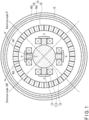
- FIG. 1 is a diagram illustrating an example of a cross-sectional shape (a shape of a cross section perpendicular to a rotary shaft) of a portion of a rotating electrical machine according to an embodiment.
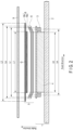
- FIG. 2 is a diagram illustrating an example of a sectional shape (a shape of a cross section parallel to the rotary shaft) of a portion of the rotating electrical machine.
- the rotating electrical machine includes a rotor 1, a stator 5 provided on a radially outer side of the rotor 1 so as to be spaced apart from the rotor 1, and a frame 9 provided on a radially outer side of the stator 5 so as to be spaced apart from the stator 5.
- the rotor 1 includes a rotary shaft 2, a rotor coil (field unit) 3, and a rotor coil support member 4.
- a case where the rotor coil is employed as field means (field unit) on the rotor side is exemplified, but a permanent magnet may be employed instead of the rotor coil.
- the rotary shaft 2 is a shaft that rotates as a central axis of the rotor 1.
- the rotor coil 3 is supported by a rotor coil support member 4 so as to be rotatable together with the rotary shaft 2.
- the rotor coil 3 is wound around the rotor coil support member 4 in a shape close to a rectangular shape, and functions as a field unit that generates a magnetic field.
- the rotor coil support member 4 is fixed to the rotary shaft 2 and stably supports the rotor coil 3 so as to counteract a centrifugal force caused by the rotation of the rotor 1.
- the rotor coil support member 4 is made of, for example, a magnetic body. In this case, the rotor coil support member 4 functions as a rotor magnetic pole.
- the rotor coil support member 4 may be made of a non-magnetic material (non-magnetic body). In this case, the rotor coil 3 functions as an air-core coil.
- the rotor coil support member 4 is constituted by four members, and four magnetic poles (two N poles and two S poles) are formed.
- the number of members constituting the rotor coil support member 4 is not limited to four (the number of the magnetic poles may be a number other than four).
- the stator 5 includes a stator coil 6 and a plurality of magnetic shields 8.
- the stator coil 6 generates a magnetic field that interacts with a magnetic field generated by the rotor coil (field unit) 3.
- the plurality of magnetic shields 8 are provided on the radially outer side of the stator coil 6, and are formed of a plurality of cylindrical magnetic bodies arranged so as to be separated from each other by a predetermined distance in the radial direction.
- Each of the plurality of magnetic shields 8 is formed of a plurality of annular electromagnetic steel sheets stacked in an axial direction of the rotating electrical machine.
- the plurality of magnetic shields 8 include a magnetic shield (first magnetic shield) 8a disposed on a radially inner side and a magnetic shield (second magnetic shield) 8b disposed on a radially outer side of the magnetic shield 8a. That is, the two magnetic shields 8a and 8b form a double-cylindrical shield structure.
- another magnetic shield for example, a disc-shaped magnetic shield
- another magnetic shield for example, a disc-shaped magnetic shield
- a gap G is provided between the magnetic shield 8a and the magnetic shield 8b.
- a non-magnetic body may be further provided.
- a refrigerant such as a cooling gas flows through the gap G, to reduce the heat generated in the magnetic shields 8a and 8b.
- the non-magnetic body is disposed so as to maintain a uniform interval between the magnetic shield 8a and the magnetic shield 8b, and functions as a support member that supports and fixes the magnetic shields 8a and 8b. Details of the non-magnetic body will be described later.
- the embodiment is not limited to this case, and three or more magnetic shields may be disposed to be separated from each other in the radial direction. That is, the shield structure is not limited to the double cylinder, and a multiple cylinder shield including three or more magnetic shields may be formed.
- L1 indicates a length of the magnetic shield 8a in the axial direction.
- L2 indicates a length of the magnetic shield 8b in the axial direction.
- Lr indicates a length of the rotor coil 3 in the axial direction.
- Ls indicates a length of the stator coil 6 in the axial direction.
- Lb indicates a length of a linear portion extending linearly in the axial direction of each of the rotor coil 3 and the stator coil 6.
- Le indicates a length of a line in the axial direction connecting axial center positions of two coil end portions extending from both sides of a coil portion of a linear portion extending linearly in the axial direction of the stator coil 6, or a length of a line in the axial direction connecting axial center positions of two coil portions extending in a rotational direction of the rotor coil 3.
- the rotor coil 3 and the stator coil 6 each have a linear portion extending linearly in the axial direction of the rotary shaft 2.
- the length of the linear portion is assumed to be Lb.
- the length of the linear portion of the rotor coil 3 and the length of the linear portion of the stator coil 6 are equal to each other, but the embodiment is not limited to this example, and the lengths of the linear portions may be different from each other.
- the rotor coil 3 and the stator coil 6 each have the linear portion and end portions which are located on both outer sides in the axial direction and are connected to other linear portions.
- the end portions correspond to portions called coil end portions in the stator coil 6, and extend from the coil portion of the linear portion extending in the axial direction to both sides in the axial direction.
- the end portions correspond to coil portions that continuously connect a coil portion of a linear portion extending in the axial direction and a coil portion extending in the rotational direction in the rotor coil 3, and are located at positions protruding from the rotor coil support member 4 on both sides in the axial direction.
- the magnetic field generated by the rotating rotor coil 3 generates electric power in the stator coil 6 on the stator 5 side by electromagnetic induction in a case where the rotating electrical machine operates as a generator, and generates torque by interaction with the magnetic field generated by the current flowing in the stator coil 6 on the stator 5 side, thereby rotating the rotor 1, in a case where the rotating electrical machine operates as a motor.
- the magnetic field caused by the rotor coil 3 and the stator coil 6 is directed toward the plurality of magnetic shields 8 located on the radially outer side of the stator coil 6, but the magnetic field (leakage magnetic field) leaking to the outside of the plurality of magnetic shields 8 is reduced by the shielding effect of the plurality of magnetic shields 8.
- FIG. 3 is a graph illustrating results of numerical analyses of magnetic flux density distributions along the circumferential direction of a leakage magnetic field leaking to a radially outer side of a shield structure regarding the embodiment and a conventional example, respectively.
- the horizontal axis of the graph indicates a circumferential position of the magnetic shield around the rotary shaft 2 (the electrical angle of the rotating electrical machine, that is, the electrical angle when one pole of the rotating electrical machine corresponds to 0 to 180 degrees), and the vertical axis indicates a magnetic flux density in the radial direction in the space on the radially outer side of the shield structure. It is assumed that the space at the position where the magnetic flux density is examined is a nonmagnetic space, and the ratio of the magnetic flux density is the same as the ratio of the magnetic field.
- the shield structure is formed in a single cylinder like the magnetic shield 80 shown in FIGS. 7 and 8
- the shield structure is formed in a double cylinder like the magnetic shields 8a and 8b shown in FIGS. 1 and 2 .
- a symbol B1 indicates characteristics of the magnetic flux density distribution of the single cylinder according to the conventional example
- a symbol B2 indicates characteristics of the magnetic flux density distribution of the double cylinder according to the present embodiment.
- the sectional area of the conventional magnetic shield 80 shown in FIG. 7 is made equal to the sum of sectional areas of the magnetic shields 8a and 8b of the present embodiment shown in FIG. 1 , whereby the weight per unit length of the single cylinder is made equal to that of the double cylinder.
- the thicknesses of the magnetic shields 8a and 8b of the double cylinder in the radial direction are the same.
- the magnetic flux density of the leakage magnetic field leaking to the radially outer side of the shield structure is smaller and a higher shield effect can be obtained in the characteristics B2 of the double cylinder according to the present embodiment than in the characteristic B1 of the single cylinder according to the conventional example.
- the peaks of the magnetic flux density observed at the electrical angles of about 20 degrees and about 160 degrees are significantly reduced, and a higher shielding effect can be obtained.
- the magnetic fluxes at the respective peaks are denoted by ⁇ 1 and ⁇ 2, and the lines of magnetic fluxes are shown in FIG. 1 .
- the magnetic shields 8a and 8b of the present embodiment can provide the effect of reducing the leakage magnetic field.
- the magnetic fluxes directed from the magnetic poles toward the radially outer side enter and exit the gap G from the magnetic shields 8a, and the directions of the magnetic fluxes are changed when entering and exiting the magnetic shields 8b from the gap G.
- the magnetic fluxes ⁇ 1 and ⁇ 2 are directed from the magnetic poles toward the radially outer side while drawing arcs as shown in FIG. 1 , so as to pass through the magnetic shield 8a, the gap G, and the magnetic shield 8b in this order.
- the directions of parts of the magnetic fluxes ⁇ 1 and ⁇ 2 are changed to be directed in the circumferential direction rather than the radially outer direction, and the parts of the magnetic fluxes ⁇ 1 and ⁇ 2 travel in the circumferential direction.
- the density of the magnetic flux of the magnetic field leaking to the radially outer side of the magnetic shield 8b is smaller than that of the conventional example.
- the leakage magnetic field becomes smaller than that of the single cylinder, and therefore, if the cross-sectional dimension of the double cylinder, that is, the weight per unit length, is determined so that the leakage magnetic field becomes the same level as that of the single cylinder, the weight of the magnetic body constituting the shield structure can be reduced.
- FIG. 4 is a conceptual diagram illustrating a magnetic flux density distribution along the axial direction of the leakage magnetic field leaking to the radially outer side of a double cylinder according to the embodiment, superimposed on a magnetic flux density distribution along the axial direction of the leakage magnetic field leaking to the radially outer side of a conventional single cylinder.
- a symbol B3 indicates characteristics of the magnetic flux density distribution of the single cylinder according to the conventional example
- a symbol B4 indicates characteristics of the magnetic flux density distribution of the double cylinder according to the present embodiment.
- the sectional area of the conventional magnetic shield 80 shown in FIG. 7 is also made equal to the sum of sectional areas of the magnetic shields 8a and 8b of the embodiment shown in FIG. 1 , whereby the weight per unit length of the single cylinder is made equal to that of the double cylinder.
- the thicknesses of the two magnetic shields of the double cylinder in the radial direction are the same.
- the double cylinder according to the present embodiment is configured such that two layers of magnetic shields are present in a range corresponding to the central portion in the axial direction of the stator 5 and one layer of magnetic shield is present in ranges corresponding to both end portions in the axial direction of the stator 5 as shown in FIG. 2 , and therefore, a high shielding effect can be obtained while achieving a reduction in size and weight of the shield structure.
- the magnetic flux density of the leakage magnetic field leaking to the radially outer side of the shield structure is smaller in the characteristics B4 of the double cylinder according to the present embodiment than in the characteristics B3 of the single cylinder according to the conventional example, and it is understood that a high shielding effect can be obtained.
- the magnetic shields 8a and 8b may be supported and fixed by a support member or the like so as to maintain a uniform interval.
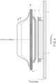
- FIG. 5 is a diagram illustrating an example of a cross-sectional shape (a shape of a cross section perpendicular to the rotary shaft) of a shield structure in which magnetic shield support members 11 are provided between magnetic shields 8a and 8b.
- a plurality of magnetic shield support members 11 as non-magnetic bodies are disposed between the magnetic shields 8a and 8b at equal intervals in the circumferential direction.
- a refrigerant such as a cooling gas flows through the plurality of gaps G formed by the arrangement of the plurality of magnetic shield support members 11, to reduce the heat generated in the magnetic shields 8a and 8b.
- a structure is adopted in which a non-magnetic body is disposed as the magnetic shield support members 11 between the magnetic shields 8a and 8b.
- the magnetic shield support members 11 are arranged so as to secure contact areas between the magnetic shields 8a and 8b, whereby heat conduction is satisfactorily performed between the two magnetic shields, to reduce heat generated in the magnetic shields 8a and 8b.
- the length L1 in the axial direction of the magnetic shield 8a which is disposed radially inward of the plurality of magnetic shields 8, is set to be shorter than the length L2 in the axial direction of the magnetic shield 8b disposed radially outward from the magnetic shield 8a.
- the length L1 in the axial direction of the magnetic shield 8a is set to be equal to or longer than the lengths Lb in the axial direction of the linear portions of the rotor coil 3 and the stator coil 6 extending linearly in the axial direction.
- the magnetic shield 8a is disposed in a range where the magnetic field generated by the stator coil 6 and the rotor coil 3 is strong (a range of lengths substantially equal to the lengths of the linear portions of the coils). In this range, both the magnetic shield 8a and the magnetic shield 8b contribute to shielding of the magnetic field, and in a range where only the magnetic shield 8b is singly provided (a range corresponding to the coil end portion), the magnetic shield 8b contributes to shielding of a weaker magnetic field.
- the lengths of the magnetic shields 8a and 8b in the axial direction are preferably set as follows, although the optimum lengths of the magnetic shields 8a and 8b in the axial direction vary depending on the geometric shapes of the stator coil 6 and the rotor coil 3, such as the lengths thereof, the circumferential range thereof, and the inclination thereof with respect to the axial direction at the end portions thereof.
- the length L1 of the magnetic shield 8a in the axial direction is preferably shorter than the length Le of a line in the axial direction connecting axial center positions of two coil end portions extending from both sides of a coil portion of a linear portion extending linearly in the axial direction of the stator coil 6, or shorter than the length Le of a line in the axial direction connecting axial center positions of two coil portions extending in a rotational direction of the rotor coil 3.
- This configuration does not hinder the work around the coil end portions, and can shield the magnetic field generated by each coil.
- the length L2 of the magnetic shield 8b in the axial direction is preferably longer than the length Ls of the stator coil 6 in the axial direction or the length Lr of the rotor coil 3 in the axial direction.
- an additional magnetic shield may be provided in the space between the magnetic shield 8a and the magnetic shield 8b.
- the length of the additional shield in the axial direction is longer than the length L1 of the magnetic shield 8a in the axial direction on the radially inner side and shorter than the length L2 of the magnetic shield 8b in the axial direction on the radially outer side. That is, in the case where three or more magnetic shields 8 are provided, the magnetic shields are configured so that the length of each magnetic shield in the axial direction is shorter toward the radially inner side and longer toward the radially outer side.
- the magnetic shield is configured to have a larger number of layers toward the center portion of the stator 5 in the axial direction and a smaller number of layers toward both end portions of the stator 5 in the axial direction, and thus, a high shielding effect can be obtained while achieving a reduction in size and weight of the shield structure.
- the magnetic resistance in the circumferential direction of the magnetic shield 8a disposed on the radially inner side among the plurality of magnetic shields 8 shown in FIGS. 1 and 2 may be set to be smaller than the magnetic resistance in the circumferential direction of the magnetic shield 8b disposed on the radially outer side of the magnetic shield 8a.
- the magnetic resistance is expressed by "length of magnetic path / (magnetic permeability ⁇ cross-sectional area)".
- the magnetic permeability in the circumferential direction of the material of the magnetic shield 8a on the radially inner side may be set to be higher than the magnetic permeability in the circumferential direction of the material of the magnetic shield 8b on the radially outer side.
- a grain-oriented electromagnetic steel sheet may be used for the magnetic shield 8a on the radially inner side
- a non-grain-oriented electromagnetic steel sheet may be used for the magnetic shield 8b on the radially outer side.
- the grain-oriented electromagnetic steel sheet is disposed such that the easy magnetization direction (direction in which magnetic moments are easily oriented) of the grain-oriented electromagnetic steel sheet is substantially oriented in the circumferential direction.
- the easy magnetization direction direction in which magnetic moments are easily oriented
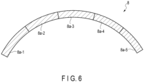
- FIG. 6 a plurality of fan-shaped units 8a-1, 8a-2, 8a-3, etc., constituting the magnetic shield 8a are prepared, and then the units are joined so as to be connected in the circumferential direction.
- Each unit is formed by laminating a plurality of grain-oriented electromagnetic steel sheets.
- the plurality of grain-oriented electromagnetic steel sheets may be cut into a fan shape so that the easy magnetization direction is oriented in the circumferential direction when the grain-oriented electromagnetic steel sheets are joined. Then, the units are joined so as to be connected in the circumferential direction.
- the magnetic shield 8a on the radially inner side, on which a stronger magnetic field is incident has a small magnetic resistance in the circumferential direction, and thus a part of the magnetic fluxes is changed in direction to be directed in the circumferential direction rather than in the radially outer direction, and the magnetic fluxes directed in the radially outer direction are reduced.
- the magnetic shield 8b on the radially outer side has a large magnetic resistance in the circumferential direction; however, since the magnetic field incident thereon is weak, the shielding effect required for the magnetic shield on the radially outer side alone may be low. In general, a material having a large magnetic resistance is more easily obtainable than a material having a small magnetic resistance, and thus the material cost at the time of manufacturing can be suppressed.
- the space factor in the axial direction of the magnetic shield 8a on the radially inner side may be set to be higher than the space factor in the axial direction of the magnetic shield 8b on the radially outer side.
- a material having a larger plate thickness than the magnetic shield 8b on the radially outer side may be used for the magnetic shield 8a on the radially inner side.
- an electromagnetic steel sheet having a 0.5 mm thickness may be used for the magnetic shield 8a on the radially inner side
- an electromagnetic steel sheet having a 0.35 mm thickness may be used for the magnetic shield 8b on the radially outer side.
- a material having a smaller iron loss than the magnetic shield 8b on the radially outer side may be used for the magnetic shield 8a on the radially inner side.
- a material having a smaller thickness than the magnetic shield 8b on the radially outer side may be used for the magnetic shield 8a on the radially inner side.
- low-loss electromagnetic steel sheets of a higher grade than the magnetic shield 8b on the radially outer side may be used for the magnetic shield 8a on the radially inner side; that is, an electromagnetic steel sheet of JIS standard 50A250 may be used for the magnetic shield 8a on the radially inner side, and an electromagnetic steel sheet of JIS standard 50A470 may be used for the magnetic shield 8b on the radially outer side.
- the method of using a material thinner than the magnetic shield 8b on the radially outer side for the magnetic shield 8a on the radially inner side is opposite that of using a material thicker than the magnetic shield 8b on the radially outer side for the magnetic shield 8a on the radially inner side; which method is selected may be determined according to the intended purpose and use conditions of the rotating electrical machine. For example, the determination may be made according to whether to prioritize obtaining a higher shielding effect by reducing the magnetic resistance of the magnetic shield 8a on the radially inner side, or to prioritize suppressing a temperature rise in the magnetic shield and a decrease in the performance of the rotating electrical machine after obtaining a shielding effect of a certain level.
- the cylindrical magnetic shields are made of magnetic bodies formed of a plurality of magnetic shields spaced apart from one another in the radial direction, and thus it is possible to reduce the leakage magnetic field if a magnetic body having the same volume is used. That is, when the leakage magnetic field is set to the same level, the volume of the magnetic body can be reduced.
Landscapes
- Engineering & Computer Science (AREA)
- Power Engineering (AREA)
- Physics & Mathematics (AREA)
- Electromagnetism (AREA)
- Iron Core Of Rotating Electric Machines (AREA)
- Motor Or Generator Frames (AREA)
- Synchronous Machinery (AREA)
Applications Claiming Priority (2)
| Application Number | Priority Date | Filing Date | Title |
|---|---|---|---|
| JP2022021452A JP2023118485A (ja) | 2022-02-15 | 2022-02-15 | 回転電機 |
| PCT/JP2023/002065 WO2023157576A1 (ja) | 2022-02-15 | 2023-01-24 | 回転電機 |
Publications (2)
| Publication Number | Publication Date |
|---|---|
| EP4481997A1 true EP4481997A1 (de) | 2024-12-25 |
| EP4481997A4 EP4481997A4 (de) | 2026-02-11 |
Family
ID=87578403
Family Applications (1)
| Application Number | Title | Priority Date | Filing Date |
|---|---|---|---|
| EP23756104.8A Pending EP4481997A4 (de) | 2022-02-15 | 2023-01-24 | Elektrische drehmaschine |
Country Status (3)
| Country | Link |
|---|---|
| EP (1) | EP4481997A4 (de) |
| JP (1) | JP2023118485A (de) |
| WO (1) | WO2023157576A1 (de) |
Families Citing this family (1)
| Publication number | Priority date | Publication date | Assignee | Title |
|---|---|---|---|---|
| CN118139402B (zh) * | 2024-05-07 | 2024-07-30 | 上海隐冠半导体技术有限公司 | 一种磁屏蔽结构及运动平台 |
Family Cites Families (6)
| Publication number | Priority date | Publication date | Assignee | Title |
|---|---|---|---|---|
| JPS6162345A (ja) * | 1984-08-31 | 1986-03-31 | Mitsubishi Electric Corp | 円板駆動モ−タ− |
| DE4406471C2 (de) * | 1994-02-23 | 1998-04-09 | Mannesmann Sachs Ag | Rotierende elektrische Maschine mit Außenläufer |
| JPH1073872A (ja) * | 1996-08-30 | 1998-03-17 | Nikon Corp | 磁気記録/読み込み可能なカメラ |
| JP5002671B2 (ja) * | 2010-03-31 | 2012-08-15 | 株式会社日立製作所 | 回転電機 |
| GB201116948D0 (en) * | 2011-10-03 | 2011-11-16 | Rolls Royce Plc | A magnetic shield |
| CN210927309U (zh) * | 2019-12-31 | 2020-07-03 | 苏州众泽医疗科技有限公司 | 一种中空电机结构 |
-
2022
- 2022-02-15 JP JP2022021452A patent/JP2023118485A/ja active Pending
-
2023
- 2023-01-24 EP EP23756104.8A patent/EP4481997A4/de active Pending
- 2023-01-24 WO PCT/JP2023/002065 patent/WO2023157576A1/ja not_active Ceased
Also Published As
| Publication number | Publication date |
|---|---|
| WO2023157576A1 (ja) | 2023-08-24 |
| EP4481997A4 (de) | 2026-02-11 |
| JP2023118485A (ja) | 2023-08-25 |
Similar Documents
| Publication | Publication Date | Title |
|---|---|---|
| US7652404B2 (en) | Synchronous reluctance machine | |
| US11270831B2 (en) | Three-phase reactor comprising iron-core units and coils | |
| KR102677657B1 (ko) | 자기 기어 장치 및 자기 기어 장치를 위한 폴 피스 | |
| EP1193845B1 (de) | Hybrider synchronmotor mit ringförmiger wicklung | |
| US20110234033A1 (en) | Combination radial/axial electromagnetic actuator with an improved axial frequency response | |
| CN102208837B (zh) | 旋转电机 | |
| US20080238236A1 (en) | Switched reluctance machine | |
| JP5365074B2 (ja) | アキシャルギャップ型回転電機 | |
| JP2020065435A (ja) | 電気モータのための磁束シールド | |
| EP4481997A1 (de) | Elektrische drehmaschine | |
| JP2006518180A (ja) | モータ/ジェネレータのための拡張コア | |
| JP2019140792A (ja) | アキシャルギャップ型回転電機 | |
| JP2013219906A (ja) | 単相誘導モータ | |
| JP2018108007A (ja) | 磁力抵抗を減少させた発電機 | |
| JP2005269693A (ja) | 永久磁石モータ | |
| JP2013215028A (ja) | 単相誘導モータ | |
| JP5819216B2 (ja) | 回転電機 | |
| US20240213835A1 (en) | Motor | |
| JP2024165482A (ja) | 回転電機 | |
| JP7600065B2 (ja) | 回転電機 | |
| EP4648262A1 (de) | Statorstruktur einer elektrischen drehmaschine | |
| WO2024195734A1 (ja) | モータ | |
| JP2025005133A (ja) | 回転電気機械 | |
| JP2018026894A (ja) | 回転電機のステータ | |
| KR20240099982A (ko) | 모터 구조 및 분할 코어 적층 방법 |
Legal Events
| Date | Code | Title | Description |
|---|---|---|---|
| STAA | Information on the status of an ep patent application or granted ep patent |
Free format text: STATUS: THE INTERNATIONAL PUBLICATION HAS BEEN MADE |
|
| PUAI | Public reference made under article 153(3) epc to a published international application that has entered the european phase |
Free format text: ORIGINAL CODE: 0009012 |
|
| STAA | Information on the status of an ep patent application or granted ep patent |
Free format text: STATUS: REQUEST FOR EXAMINATION WAS MADE |
|
| 17P | Request for examination filed |
Effective date: 20240702 |
|
| AK | Designated contracting states |
Kind code of ref document: A1 Designated state(s): AL AT BE BG CH CY CZ DE DK EE ES FI FR GB GR HR HU IE IS IT LI LT LU LV MC ME MK MT NL NO PL PT RO RS SE SI SK SM TR |
|
| DAV | Request for validation of the european patent (deleted) | ||
| DAX | Request for extension of the european patent (deleted) | ||
| A4 | Supplementary search report drawn up and despatched |
Effective date: 20260113 |
|
| RIC1 | Information provided on ipc code assigned before grant |
Ipc: H02K 5/00 20060101AFI20260107BHEP Ipc: H02K 19/14 20060101ALI20260107BHEP Ipc: H02K 1/24 20060101ALI20260107BHEP Ipc: H02K 3/52 20060101ALI20260107BHEP Ipc: H02K 19/00 20060101ALN20260107BHEP |