EP4480432A2 - Systeme und verfahren für ein dissektionswerkzeug - Google Patents
Systeme und verfahren für ein dissektionswerkzeug Download PDFInfo
- Publication number
- EP4480432A2 EP4480432A2 EP24205364.3A EP24205364A EP4480432A2 EP 4480432 A2 EP4480432 A2 EP 4480432A2 EP 24205364 A EP24205364 A EP 24205364A EP 4480432 A2 EP4480432 A2 EP 4480432A2
- Authority
- EP
- European Patent Office
- Prior art keywords
- fluid
- distal
- medical device
- tissue
- valve
- Prior art date
- Legal status (The legal status is an assumption and is not a legal conclusion. Google has not performed a legal analysis and makes no representation as to the accuracy of the status listed.)
- Pending
Links
- 238000002224 dissection Methods 0.000 title description 10
- 239000012530 fluid Substances 0.000 claims abstract description 184
- 238000000034 method Methods 0.000 claims description 26
- 210000001519 tissue Anatomy 0.000 description 105
- 238000002271 resection Methods 0.000 description 32
- 230000007246 mechanism Effects 0.000 description 7
- 239000007787 solid Substances 0.000 description 4
- 206010028980 Neoplasm Diseases 0.000 description 3
- 210000003205 muscle Anatomy 0.000 description 3
- 230000000451 tissue damage Effects 0.000 description 3
- 231100000827 tissue damage Toxicity 0.000 description 3
- XLYOFNOQVPJJNP-UHFFFAOYSA-N water Substances O XLYOFNOQVPJJNP-UHFFFAOYSA-N 0.000 description 3
- FAPWRFPIFSIZLT-UHFFFAOYSA-M Sodium chloride Chemical compound [Na+].[Cl-] FAPWRFPIFSIZLT-UHFFFAOYSA-M 0.000 description 2
- 230000008901 benefit Effects 0.000 description 2
- 230000015271 coagulation Effects 0.000 description 2
- 238000005345 coagulation Methods 0.000 description 2
- 238000012790 confirmation Methods 0.000 description 2
- 230000007423 decrease Effects 0.000 description 2
- 230000003111 delayed effect Effects 0.000 description 2
- 238000003745 diagnosis Methods 0.000 description 2
- 238000001839 endoscopy Methods 0.000 description 2
- 230000002496 gastric effect Effects 0.000 description 2
- 238000009413 insulation Methods 0.000 description 2
- 230000008569 process Effects 0.000 description 2
- 208000035965 Postoperative Complications Diseases 0.000 description 1
- 230000004888 barrier function Effects 0.000 description 1
- 238000001574 biopsy Methods 0.000 description 1
- 230000000903 blocking effect Effects 0.000 description 1
- 239000008280 blood Substances 0.000 description 1
- 210000004369 blood Anatomy 0.000 description 1
- 238000013276 bronchoscopy Methods 0.000 description 1
- 201000011510 cancer Diseases 0.000 description 1
- 230000001112 coagulating effect Effects 0.000 description 1
- 239000011248 coating agent Substances 0.000 description 1
- 238000000576 coating method Methods 0.000 description 1
- 239000004020 conductor Substances 0.000 description 1
- 230000006378 damage Effects 0.000 description 1
- 230000003247 decreasing effect Effects 0.000 description 1
- 238000001514 detection method Methods 0.000 description 1
- 238000002059 diagnostic imaging Methods 0.000 description 1
- 230000009977 dual effect Effects 0.000 description 1
- 230000000694 effects Effects 0.000 description 1
- 210000003038 endothelium Anatomy 0.000 description 1
- 238000005516 engineering process Methods 0.000 description 1
- 210000001035 gastrointestinal tract Anatomy 0.000 description 1
- 230000002439 hemostatic effect Effects 0.000 description 1
- 238000002347 injection Methods 0.000 description 1
- 239000007924 injection Substances 0.000 description 1
- 239000011810 insulating material Substances 0.000 description 1
- 239000007788 liquid Substances 0.000 description 1
- 239000000463 material Substances 0.000 description 1
- 230000013011 mating Effects 0.000 description 1
- 239000002184 metal Substances 0.000 description 1
- 238000012986 modification Methods 0.000 description 1
- 230000004048 modification Effects 0.000 description 1
- 210000000056 organ Anatomy 0.000 description 1
- 239000011780 sodium chloride Substances 0.000 description 1
- 238000006467 substitution reaction Methods 0.000 description 1
- 238000001356 surgical procedure Methods 0.000 description 1
Images


Classifications
-
- A—HUMAN NECESSITIES
- A61—MEDICAL OR VETERINARY SCIENCE; HYGIENE
- A61B—DIAGNOSIS; SURGERY; IDENTIFICATION
- A61B17/00—Surgical instruments, devices or methods
- A61B17/32—Surgical cutting instruments
- A61B17/3203—Fluid jet cutting instruments
-
- A—HUMAN NECESSITIES
- A61—MEDICAL OR VETERINARY SCIENCE; HYGIENE
- A61B—DIAGNOSIS; SURGERY; IDENTIFICATION
- A61B18/00—Surgical instruments, devices or methods for transferring non-mechanical forms of energy to or from the body
- A61B18/04—Surgical instruments, devices or methods for transferring non-mechanical forms of energy to or from the body by heating
- A61B18/12—Surgical instruments, devices or methods for transferring non-mechanical forms of energy to or from the body by heating by passing a current through the tissue to be heated, e.g. high-frequency current
- A61B18/14—Probes or electrodes therefor
- A61B18/1492—Probes or electrodes therefor having a flexible, catheter-like structure, e.g. for heart ablation
-
- A—HUMAN NECESSITIES
- A61—MEDICAL OR VETERINARY SCIENCE; HYGIENE
- A61B—DIAGNOSIS; SURGERY; IDENTIFICATION
- A61B18/00—Surgical instruments, devices or methods for transferring non-mechanical forms of energy to or from the body
- A61B2018/00053—Mechanical features of the instrument of device
- A61B2018/00059—Material properties
- A61B2018/00071—Electrical conductivity
- A61B2018/00077—Electrical conductivity high, i.e. electrically conducting
-
- A—HUMAN NECESSITIES
- A61—MEDICAL OR VETERINARY SCIENCE; HYGIENE
- A61B—DIAGNOSIS; SURGERY; IDENTIFICATION
- A61B18/00—Surgical instruments, devices or methods for transferring non-mechanical forms of energy to or from the body
- A61B2018/00571—Surgical instruments, devices or methods for transferring non-mechanical forms of energy to or from the body for achieving a particular surgical effect
- A61B2018/00589—Coagulation
-
- A—HUMAN NECESSITIES
- A61—MEDICAL OR VETERINARY SCIENCE; HYGIENE
- A61B—DIAGNOSIS; SURGERY; IDENTIFICATION
- A61B18/00—Surgical instruments, devices or methods for transferring non-mechanical forms of energy to or from the body
- A61B2018/00571—Surgical instruments, devices or methods for transferring non-mechanical forms of energy to or from the body for achieving a particular surgical effect
- A61B2018/00601—Cutting
-
- A—HUMAN NECESSITIES
- A61—MEDICAL OR VETERINARY SCIENCE; HYGIENE
- A61B—DIAGNOSIS; SURGERY; IDENTIFICATION
- A61B90/00—Instruments, implements or accessories specially adapted for surgery or diagnosis and not covered by any of the groups A61B1/00 - A61B50/00, e.g. for luxation treatment or for protecting wound edges
- A61B90/03—Automatic limiting or abutting means, e.g. for safety
Definitions
- the present disclosure relates generally to medical devices, including endoscopic devices for tissue resection.
- embodiments of this disclosure relate to systems and devices for a fluid powered endoscopic dissection tool.
- Tumor resection and other tissue treatment is often performed by medical devices (e.g., endoscopic devices) by delivering radio frequency (RF) energy to destroy tissue.
- RF radio frequency
- tissue architecture may be destroyed during RF energy delivery, there may be a delayed or incomplete medical confirmation of a successful tissue resection.
- the destroyed tissue architecture may delay or inhibit proper biopsy and classification of the treated tissue.
- RF energy delivery devices may cause postoperative complications and tissue artifact as a result of, for example, delayed tissue effects. Therefore, a need exists for a fast, accurate, and precise method of resection with minimal collateral tissue damage.
- a medical device comprising a body that has a proximal end with a proximal opening.
- the body defines a channel from the proximal opening to a distal opening configured to emit a fluid jet along a longitudinal axis of the body.
- the body further includes a distal wall surface that has a surface extending in a direction transverse to the longitudinal axis and faces the distal opening to receive the fluid jet.
- the body defines a space between the distal wall surface and the distal opening.
- the distal wall includes a protrusion configured to engage tissue.
- a medical device comprises a tubular member that has a proximal end couplable to a fluid source and a distal end.
- the medical device has a fluid channel disposed in the tubular member and is configured to deliver fluid from the proximal end of the tubular member through the tubular member to the distal end.
- the medical device has a nozzle located at the distal end of the tubular member.
- the nozzle is configured to emit a fluid jet along a longitudinal axis.
- the distal wall has a surface extending in a direction transverse to the longitudinal axis and faces the nozzle to receive the fluid jet.
- the wall includes a protrusion configured to engage tissue.
- the medical device defines a space between the nozzle and the distal wall.
- a method of medical tissue comprises placing a medical device proximate a tissue of interest, engaging the tissue of interest with a protrusion of the medical device to hold the medical device in a position proximate the tissue of interest, and emitting fluid from a distal opening of the medical device towards a distal wall surface of the medical device along a longitudinal axis. The fluid pierces the tissue of interest.
- Tissue dissection and specifically tissue/tumor resection and removal, may benefit from a medical device that implements a fast, accurate, and precise method of resection with minimal collateral tissue damage.
- medical devices may be more effective and advantageous than medical devices that deliver only radio frequency (RF) energy to perform tissue resection, for example, by preserving tissue architecture for confirmation of medical diagnosis and for effective tissue treatment.
- RF radio frequency
- fluid may be delivered to perform tissue dissection techniques (e.g., submucosal dissection).
- Fluid powered systems may be configured to dissect or resect tissue effectively with high precision and low heat. Additionally, fluid powered resection systems may be combined with RF or other energy delivery technologies to provide coagulation and hemostatic function during tissue resection.
- fluid powered tissue resection techniques may lead to reduced blood loss during a surgical procedure, and the low temperature helps preserve tissue and vessel architecture. Resection depth can also be controlled with varying fluid pressure applications. Therefore, aspects of the present disclosure are directed to medical devices with fluid powered tissue resection systems.
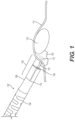
- FIG. 1 depicts an example medical device 102.
- the medical device 102 may be, for example, an endoscopic medical device, such as a catheter, used to perform tissue resection methods (e.g., submucosal tissue dissection).
- the medical device 102 has a tubular member 104 with a proximal end (not shown) and a distal end 106.
- the tubular member 104 may be any known or contemplated tubular member 104 used for medical procedures, such as endoscopy, and may be, for example, a flexible tubular member with one or more channels or lumens disposed therein and extending between the proximal and distal ends 106 of the tubular member 104 for medical operation.
- the handle may be any known or contemplated handle used for medical procedures, and may include suitable ports and plugs for fluid and/or energy delivery. Additionally, the medical device 102 has a fluid delivery mechanism (not shown) located at the proximal end of the tubular member 104.
- the fluid delivery mechanism may or may not be part of the handle, and enables fluid to flow from the proximal end of the tubular member 104, via one or more internal channel or lumens, to the distal end 106 and ultimately to a body 108 to perform the fluid powered tissue resection techniques described herein.
- the fluid delivery mechanism may include a fluid source that is disposed at the proximal end of the tubular member 104, for example within the handle.
- the fluid delivery mechanism may be a mechanism to drive fluid through the tubular member 104 (e.g., a pump) from a remote fluid source.
- the medical device 102 also includes a body 108 disposed on the distal end 106 of the tubular member 104.
- the body 108 has a proximal end 110 and a distal end 112.
- the proximal end 110 of the body 108 is configured to interface with/engage the distal end 106 of the tubular member 104.
- the body 108 may plug into a mating component at the distal end 106 of the tubular member 104. It should be appreciated that any internal working channels and/or lumens may be aligned in the body 108 and the tubular member 104.
- the body 108 may be integrally formed with and permanently fixed to the tubular member 104 (e.g., by being bonded or otherwise adhered or affixed to the tubular member 104).
- the body 108 has a proximal opening (not shown in FIG. 1 ) and a distal opening 109.
- FIG. 1 also shows a tissue boundary 114.
- the tissue boundary 114 may be any tissue layer within the human body.
- FIG. 1 also shows a target tissue at reference numeral 116.
- the target tissue 116 may be a tumor located within a gastrointestinal (GI) endothelium, though it should be appreciated that this may be any tissue in the human body.
- GI gastrointestinal
- the techniques described herein enable treatment of the target tissue 116, for example, by providing a fluid powered tissue resection method.
- FIG. 1 shows the distal end 112 of the body 108 embedded below the tissue boundary 114.
- Reference numeral 118 shows a direction at which fluid may be delivered at a sufficiently high pressure to pierce the tissue boundary 114 and a tissue region 120 where treatment is being applied.
- the medical device 102 is used to resect the target tissue 116.
- FIG. 2A shows the body 108 at the distal end 106 of the tubular member 104 according to one example embodiment.
- the body 108 is configured to interface with the tubular member 104, e.g., by plugging into an opening (not shown in FIG. 1 ) at the distal end 106 of the tubular member 104.
- the body 108 has a proximal opening (not shown in FIG. 1 ) and the distal opening 109 shown in FIG. 1 .
- An interim fluid channel (not shown in FIG. 1 ) is formed in the body 108 between the proximal opening of the body 108 and the distal opening 109 of the body 108, as described herein.
- the interim fluid channel aligns with at least one channel or lumen of the tubular member 104 (e.g., catheter).
- FIG. 2A shows a fluid jet 210 that is emitted along an axis (e.g., a longitudinal axis) from the distal opening 109 of the body 108.
- FIG. 2A also shows a direction of fluid flow along the axis, at reference numeral 211.
- the proximal opening of the body 108 is configured to interface with, and receive fluid from, a fluid delivery device (e.g., the fluid delivery mechanism described in connection with FIG. 1 ) that is internal and/or external to the medical device 102.
- a fluid delivery device e.g., the fluid delivery mechanism described in connection with FIG. 1
- the proper fluid pressure may vary depending on system and device parameters, including but not limited to the tissue type, the fluid used for the fluid jet 210, the diameter of the distal opening 109 of the body 108, etc.
- the diameter of the distal opening 109 varies based on the channels of the tubular member 104 and the desired size of the intended area of tissue impact of the fluid jet 210.
- a fluid pressure of between about 20-60 bars may be used for tissue resection, with, e.g., relatively lower pressures providing cleaner and more precise tissue piercings or perforations to minimize risk.
- the distal opening 109 when the distal opening 109 has a diameter of about 0.04 inches, less than about 250 psi of fluid pressure may be sufficient to pierce tissue (e.g., muscle tissue, diseased tissue, or other types of tissue to be treated by the medical device 102), and when the distal opening 109 has a diameter of about 0.05 inches, less than about 100 psi of fluid pressure may be sufficient to pierce tissue.
- tissue e.g., muscle tissue, diseased tissue, or other types of tissue to be treated by the medical device 102
- the distal opening 109 when the distal opening 109 has a diameter of about 0.05 inches, less than about 100 psi of fluid pressure may be sufficient to pierce tissue.
- Higher fluid pressures may be desirable for tissue resection of mucosal and/or submucosal layers as opposed to fluid pressures for muscle tissue since the mucosal and submucosal layers of the GI tract may be tougher than muscle.
- fluid pressure of about 600 psi may pierce mucosal and/or submucosal tissue.
- the fluid pressure may also vary based on the type of distal opening 109 (e.g., the internal shape and the geometry of the distal opening 109).
- the distal opening 109 may be chamfered to disperse pressure, or conical/tapered inward (tapered from a proximal to distal direction) to focus the stream of fluid (e.g., fluid jet 210).
- FIG. 2A also shows an outer surface of a distal wall 220.
- the distal wall 220 extends in a direction transverse to a longitudinal axis along which the fluid jet 210 is emitted.
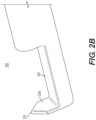
- FIG. 2B which shows a view of the body 108 according to an example embodiment, an inner, proximally-facing surface of the distal wall 220 is shown at reference numeral 220a.
- the inner surface 220a faces the distal opening 109 of the body 108.
- the 2B also shows the distal wall 220 having a protrusion 230 at a top end of the distal wall 220 and extending in the direction transverse to the longitudinal axis at which the fluid jet 210 is emitted.
- the protrusion 230 may be a relatively sharp tip of the distal wall 220 that points in a radially outward direction.
- the protrusion 230 is configured to engage tissue (e.g., to pierce the tissue surface and/or be placed on the tissue surface). For example, the protrusion 230 engages the tissue boundary 114, described in connection with FIG.
- the protrusion 230 is a hook or a hook-like feature that is configured to engage and affix to tissue.
- the protrusion 230 may comprise one or more tips or prongs.
- the protrusion 230 may prevent or limit unintended tissue perforation by blocking fluid flow past the tissue that is acquired by the protrusion 230.
- the protrusion 230 provides a solid surface (e.g., the inner surface 220a of the distal wall 220) for the fluid jet 210 to impact, which may dissipate the force of the fluid jet 210.
- the fluid may "splash back."
- the fluid splash back may be at a sufficiently low energy not to cause any damage to the surrounding healthy tissue (and, e.g., to avoid obscuring a camera view of operation).
- the protrusion 230 may be shaped to minimize the fluid energy of the splash back as the fluid jet 210 impacts the protrusion 230.
- the solid surface e.g., the inner surface 220(a) of the distal wall 220
- the solid surface e.g., the inner surface 220(a) of the distal wall 220
- the solid surface may be flat, convex, or concave relative to the flow of the fluid jet 210.
- the profiles of the distal wall 220 and the protrusion 230 may be optimized in terms of distance from the distal opening 109, shape, material, and thickness in order to direct the splash back safely. Referring back to FIG. 2A , this dissipation is shown at reference numeral 240, as fluid dissipates along the edges and sides of the body 108 and the distal wall 220 and causes minimal or no unintended tissue perforation.
- FIG. 2B also shows a bed region ("bed") 250 of the body 108.
- the bed 250 in one example is a surface disposed along the longitudinal axis between the distal opening 109 of the body 108 and the distal wall 220 of the body 108.
- the bed 250 may define a space in the body 108 for receiving tissue between the distal opening 109 and the distal wall 220.
- the bed 250 is a surface that connects the inner surface 220a of the distal wall 220 to a side of the body 108 with the distal opening 109 of the body 108.
- the bed 250 may be used during a medical procedure to remove a resected tissue from a patient's body.
- the body 108 may be maneuvered such that the target tissue 116 is placed on the bed 250 and removed from the patient's body as the medical device 102 is removed.
- the surface of bed 250 may be treated with a tacky coating or otherwise treated so that the resected tissue adheres to the surface of the bed 250.
- FIG. 3 shows a cross-sectional view of the medical device 102.
- FIG. 3 shows the cross-sectional view of the body 108 and a distal end of the tubular member 104 of the medical device 102.
- FIG. 3 shows an interim fluid channel 330 in the body 108 and a primary fluid channel 340 in the tubular member 104.
- the interim fluid channel 330 is formed between a proximal opening in the body 108 and the distal opening 109 of the body 108.
- fluid in the primary fluid channel 340 flows to the interim fluid channel 330, as shown by arrows 350, via the proximal opening of the body 108 (not shown in FIG. 3 ).
- the proximal opening of the body 108 interfaces with a distal opening of the primary fluid channel 340 such that fluid may flow between the primary fluid channel 340 and the interim fluid channel 330.
- the interim fluid channel 330 tapers from a proximal end to the distal end.
- the cross-sectional area and/or the diameter of the interim fluid channel 330 decreases from its proximal end to its distal end.
- the fluid flows at a higher pressure toward the distal end of the interim fluid channel 330 when compared to the fluid flow at the proximal end of the interim fluid channel 330 and when compared to the fluid flow in the primary fluid channel 340.
- the fluid jet 210 egresses from the interim fluid channel 330 at the distal opening 109 of the body 108, the fluid jet 210 is emitted at a higher fluid pressure relative to the fluid pressure of the primary fluid channel 340.
- the distal opening 109 of the body 108 operates as a nozzle to emit the fluid jet 210 at a high relative fluid pressure.
- the fluid pressure of the fluid jet 210 is sufficiently high to perform tissue resection operations. Splash back is limited, as shown by the water dissipation at reference 240.
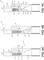
- FIG. 4A shows a tubular member 410, a distal end structure 420, and a body 425.
- the tubular member 410 may have the structure and functions of the tubular member 104, and the body 425 may have the structure and functions of the body 108.
- the distal end structure 420 may have the structure and functions of the distal end 106.
- the distal end structure 420 further includes a valve 450, and a spring 460.
- fluid may be delivered to a distal end of the medical device 102'.
- the interim fluid channel 430 holds the fluid as the interim fluid channel 430 narrows.
- the valve 450 is located in a distal portion of the interim fluid channel 430, distal to a narrowing 435 of the interim fluid channel 430.
- the narrowing 435 has a smaller diameter and/or cross-sectional area relative to portions of channel 430 distal to and proximal to the narrowing 435.
- the valve 450 is not fixed to the interim fluid channel 430 and is therefore able to translate longitudinally within channel 430, e.g., along a direction shown by arrow 405.
- the spring 460 also is located in the distal portion of the interim fluid channel 430, distal to the valve 450.
- the spring 460 is affixed to the valve 450 at a proximal end of the spring 460.
- the spring 460 and the valve 450 are positioned between a proximal opening of the interim fluid channel 430, shown at reference 462, and a proximal end of the body 425.
- the body 425 is bonded to the distal end structure 420 such that the spring 460 is affixed to a surface of the body 425 at a distal end of the spring 460.
- the spring 460 is a coil spring that is compressible upon application of pressure (e.g., upon application of fluid pressure along the direction 405 on the valve 450).
- the valve 450 is a one-way valve that allows fluid to egress from the interim fluid channel 430 in a single direction.
- FIG. 4B shows a closed state configuration of the valve 450.
- arrows 470a-470c represent fluid flowing into the interim fluid channel 430.
- the fluid pressure increases at arrow 470c as the interim fluid channel 430 narrows toward the valve 450.
- FIG. 4B the valve is closed, and thus fluid does not egress from the interim fluid channel 430.
- FIG. 4C shows an open state configuration of the valve 450. In FIG.
- a shape of the valve 450 may result in a greater area of the valve 450 exposed to fluid flow, forcing it to open quickly.
- Egress channel 480 may extend from the proximal opening 462 to the distal end structure 420, such that fluid may flow towards the body 425 e.g., in the direction of arrows 472a-472d.
- the fluid leaves the egress channel 480 and flows toward the protrusion (e.g., protrusion 230).
- the proximal pressure of the spring 460 on the valve 450 may be greater than the fluid pressure exerted on the valve 450, and the valve 450 may recede (e.g., travel in a proximal direction) to the closed state shown in FIG. 4B .
- the fluid is emitted from the interim fluid channel 430 at a constant or relatively constant pressure.
- the mechanism described in FIGs. 4A-4C enables fluid to be emitted from the egress channel 480 at a constant or near constant pressure, which avoids a scenario where the fluid pressure gradually builds up during fluid egress from the interim fluid channel 430 and the distal opening 462.
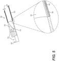
- the body 530 is configured to conduct RF energy.
- RF energy may be delivered to the body 530 via a conductive tube, wire, cable, or braid of the medical device 500.
- a conductive tube is shown at reference numeral 540 in the expanded view of the junction between the body 530 and the tubular member 520.
- the conductive tube 540 may be surrounded by insulating material, shown at reference numerals 550 (an inner insulation) and 560 (an outer insulation).
- the conductive tube 540 forms an electrical conduit to carry the RF energy to the body 530 and ultimately to distal wall 535 to coagulate tissue during a medical operation.
- the RF active components of the body 530 therefore includes the distal wall 535.
- the distal wall 535 may operate as the point of contact to the tissue to deliver RF energy for coagulation.
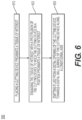
- FIG. 6 shows an example flow chart 600 depicting operations for performing the fluid-powered tissue resection techniques, described herein.
- a resection device is placed proximate a tissue of interest.
- the resection device may be any of the medical devices 102, 102', 500 described herein.
- the tissue of interest is engaged with a protrusion of the resection device to hold the resection device in a position at the tissue of interest.
- fluid is emitted from a distal opening of the resection device towards a distal wall surface of the resection device along a longitudinal axis. The fluid resects the tissue of interest.
- any of the medical devices described herein may be using in combination with any other medical device known in the art, such as medical imaging systems or other scopes such as colonoscopes, bronchoscopes, ureteroscopes, duodenoscopes, etc., or other types of imagers.
- any of the medical devices described herein may be used for resection, cutting, or otherwise dissecting tissue in any part of the human body.
- any of the medical devices described herein may be used in medical procedures where removal and/or detection of tissue is needed.
Landscapes
- Health & Medical Sciences (AREA)
- Surgery (AREA)
- Life Sciences & Earth Sciences (AREA)
- Engineering & Computer Science (AREA)
- Molecular Biology (AREA)
- Public Health (AREA)
- Heart & Thoracic Surgery (AREA)
- Medical Informatics (AREA)
- Nuclear Medicine, Radiotherapy & Molecular Imaging (AREA)
- Animal Behavior & Ethology (AREA)
- General Health & Medical Sciences (AREA)
- Biomedical Technology (AREA)
- Veterinary Medicine (AREA)
- Cardiology (AREA)
- Physics & Mathematics (AREA)
- Plasma & Fusion (AREA)
- Otolaryngology (AREA)
- Surgical Instruments (AREA)
Applications Claiming Priority (3)
| Application Number | Priority Date | Filing Date | Title |
|---|---|---|---|
| US201962887230P | 2019-08-15 | 2019-08-15 | |
| PCT/US2020/045688 WO2021030304A1 (en) | 2019-08-15 | 2020-08-11 | Systems and methods for a dissection tool |
| EP20761072.6A EP3986295B1 (de) | 2019-08-15 | 2020-08-11 | Systeme für ein sezierwerkzeug |
Related Parent Applications (2)
| Application Number | Title | Priority Date | Filing Date |
|---|---|---|---|
| EP20761072.6A Division EP3986295B1 (de) | 2019-08-15 | 2020-08-11 | Systeme für ein sezierwerkzeug |
| EP20761072.6A Division-Into EP3986295B1 (de) | 2019-08-15 | 2020-08-11 | Systeme für ein sezierwerkzeug |
Publications (2)
| Publication Number | Publication Date |
|---|---|
| EP4480432A2 true EP4480432A2 (de) | 2024-12-25 |
| EP4480432A3 EP4480432A3 (de) | 2025-03-12 |
Family
ID=72193656
Family Applications (2)
| Application Number | Title | Priority Date | Filing Date |
|---|---|---|---|
| EP20761072.6A Active EP3986295B1 (de) | 2019-08-15 | 2020-08-11 | Systeme für ein sezierwerkzeug |
| EP24205364.3A Pending EP4480432A3 (de) | 2019-08-15 | 2020-08-11 | Systeme und verfahren für ein dissektionswerkzeug |
Family Applications Before (1)
| Application Number | Title | Priority Date | Filing Date |
|---|---|---|---|
| EP20761072.6A Active EP3986295B1 (de) | 2019-08-15 | 2020-08-11 | Systeme für ein sezierwerkzeug |
Country Status (5)
| Country | Link |
|---|---|
| US (1) | US20220287766A1 (de) |
| EP (2) | EP3986295B1 (de) |
| JP (2) | JP7680422B2 (de) |
| CN (1) | CN114340520A (de) |
| WO (1) | WO2021030304A1 (de) |
Families Citing this family (1)
| Publication number | Priority date | Publication date | Assignee | Title |
|---|---|---|---|---|
| WO2024155756A1 (en) * | 2023-01-20 | 2024-07-25 | Boston Scientific Scimed, Inc. | High pressure protection for jet aspiration catheter |
Family Cites Families (16)
| Publication number | Priority date | Publication date | Assignee | Title |
|---|---|---|---|---|
| DE3715418A1 (de) * | 1986-05-08 | 1987-11-12 | Olympus Optical Co | Lithotom |
| US7429262B2 (en) * | 1992-01-07 | 2008-09-30 | Arthrocare Corporation | Apparatus and methods for electrosurgical ablation and resection of target tissue |
| CA2127637C (en) * | 1993-07-26 | 2006-01-03 | Scott Bair | Fluid jet surgical cutting tool |
| US20020169394A1 (en) * | 1993-11-15 | 2002-11-14 | Eppstein Jonathan A. | Integrated tissue poration, fluid harvesting and analysis device, and method therefor |
| US5591184A (en) * | 1994-10-13 | 1997-01-07 | Sentinel Medical, Inc. | Fluid jet surgical cutting instrument |
| US5944686A (en) * | 1995-06-07 | 1999-08-31 | Hydrocision, Inc. | Instrument for creating a fluid jet |
| US20060206028A1 (en) * | 2005-03-11 | 2006-09-14 | Qi Yu | Apparatus and method for ablating deposits from blood vessel |
| US9357977B2 (en) * | 2006-01-12 | 2016-06-07 | Gynesonics, Inc. | Interventional deployment and imaging system |
| US9254144B2 (en) * | 2007-03-30 | 2016-02-09 | Covidien Lp | Methods and apparatus for thrombectomy system |
| GB2477353B (en) * | 2010-02-01 | 2015-12-02 | Gyrus Medical Ltd | Electrosurgical instrument |
| JP5862020B2 (ja) * | 2011-02-28 | 2016-02-16 | セイコーエプソン株式会社 | 流体噴射装置 |
| PL2604202T3 (pl) * | 2011-12-14 | 2015-07-31 | Erbe Elektromedizin | Narzędzie do chirurgii strumieniowej |
| JP6403695B2 (ja) * | 2013-02-14 | 2018-10-10 | プロセプト バイオロボティクス コーポレイション | アクアアブレーションアクアビーム眼科手術方法および装置 |
| US20150112188A1 (en) * | 2013-09-20 | 2015-04-23 | Volcano Corporation | Systems and methods for monitoring endoluminal valve formation |
| US10463853B2 (en) * | 2016-01-21 | 2019-11-05 | Medtronic, Inc. | Interventional medical systems |
| US11439417B2 (en) * | 2017-01-23 | 2022-09-13 | Boston Scientific Scimed, Inc. | Necrosectomy devices and procedures |
-
2020
- 2020-08-11 JP JP2022508772A patent/JP7680422B2/ja active Active
- 2020-08-11 WO PCT/US2020/045688 patent/WO2021030304A1/en not_active Ceased
- 2020-08-11 EP EP20761072.6A patent/EP3986295B1/de active Active
- 2020-08-11 US US17/635,023 patent/US20220287766A1/en active Pending
- 2020-08-11 CN CN202080057073.8A patent/CN114340520A/zh active Pending
- 2020-08-11 EP EP24205364.3A patent/EP4480432A3/de active Pending
-
2025
- 2025-02-20 JP JP2025025987A patent/JP2025090611A/ja active Pending
Also Published As
| Publication number | Publication date |
|---|---|
| JP7680422B2 (ja) | 2025-05-20 |
| CN114340520A (zh) | 2022-04-12 |
| JP2025090611A (ja) | 2025-06-17 |
| EP3986295B1 (de) | 2024-12-04 |
| US20220287766A1 (en) | 2022-09-15 |
| WO2021030304A1 (en) | 2021-02-18 |
| EP3986295A1 (de) | 2022-04-27 |
| JP2022544268A (ja) | 2022-10-17 |
| EP4480432A3 (de) | 2025-03-12 |
Similar Documents
| Publication | Publication Date | Title |
|---|---|---|
| US8016825B2 (en) | Radio knife | |
| US9204782B2 (en) | Mucosal resection device and related methods of use | |
| JP4509722B2 (ja) | 導電性組織ストッパーを備えた内視鏡的粘膜切除装置及びその使用方法 | |
| US10835270B2 (en) | Surgical snare | |
| US9610120B2 (en) | High-frequency treatment tool for endoscope | |
| KR101814944B1 (ko) | 고주파 처치구 | |
| CN113677282B (zh) | 透热内疗装置 | |
| US10973540B2 (en) | Endoscopic surgical device | |
| CN110730636B (zh) | 内窥镜用混合刀 | |
| KR20210084467A (ko) | 전기 수술 기구 | |
| EP3954310A1 (de) | Schlaufeninjektionsvorrichtung | |
| US10765444B2 (en) | Medical instrument for ablation of tissue | |
| JP2025090611A (ja) | 解剖ツールのためのシステムおよび方法 | |
| JP2019505268A (ja) | 医療装置および使用方法 | |
| JP4695428B2 (ja) | 内視鏡用処置具 | |
| US20140276774A1 (en) | Tissue dissection device and related methods of use | |
| JP2017123996A (ja) | 内視鏡用高周波処置具 | |
| CN116059509A (zh) | 内窥镜用处置器具 | |
| JP4794214B2 (ja) | 高周波処置具 | |
| JP2017123995A (ja) | 内視鏡用高周波処置具 | |
| EP4183360B1 (de) | Ablationsvorrichtung zur befestigung an einem endoskop | |
| JP4701833B2 (ja) | 高周波処置具 | |
| JP4431892B2 (ja) | 高周波処置具 |
Legal Events
| Date | Code | Title | Description |
|---|---|---|---|
| PUAI | Public reference made under article 153(3) epc to a published international application that has entered the european phase |
Free format text: ORIGINAL CODE: 0009012 |
|
| STAA | Information on the status of an ep patent application or granted ep patent |
Free format text: STATUS: REQUEST FOR EXAMINATION WAS MADE |
|
| 17P | Request for examination filed |
Effective date: 20241108 |
|
| AC | Divisional application: reference to earlier application |
Ref document number: 3986295 Country of ref document: EP Kind code of ref document: P |
|
| AK | Designated contracting states |
Kind code of ref document: A2 Designated state(s): AL AT BE BG CH CY CZ DE DK EE ES FI FR GB GR HR HU IE IS IT LI LT LU LV MC MK MT NL NO PL PT RO RS SE SI SK SM TR |
|
| REG | Reference to a national code |
Ref country code: DE Ref legal event code: R079 Free format text: PREVIOUS MAIN CLASS: A61B0018140000 Ipc: A61B0017320300 |
|
| PUAL | Search report despatched |
Free format text: ORIGINAL CODE: 0009013 |
|
| RIN1 | Information on inventor provided before grant (corrected) |
Inventor name: LINNABARY, KIRSTEN Inventor name: KILLINGER, KYLA Inventor name: RICHARDS, LAURA EMILY |
|
| AK | Designated contracting states |
Kind code of ref document: A3 Designated state(s): AL AT BE BG CH CY CZ DE DK EE ES FI FR GB GR HR HU IE IS IT LI LT LU LV MC MK MT NL NO PL PT RO RS SE SI SK SM TR |
|
| RIC1 | Information provided on ipc code assigned before grant |
Ipc: A61B 18/14 20060101ALI20250206BHEP Ipc: A61B 17/3203 20060101AFI20250206BHEP |