EP4479351B1 - Stahlwerk mit kreislauf zur direkten kühlwasserbehandlung und zugehöriges verfahren - Google Patents
Stahlwerk mit kreislauf zur direkten kühlwasserbehandlung und zugehöriges verfahren Download PDFInfo
- Publication number
- EP4479351B1 EP4479351B1 EP23710462.5A EP23710462A EP4479351B1 EP 4479351 B1 EP4479351 B1 EP 4479351B1 EP 23710462 A EP23710462 A EP 23710462A EP 4479351 B1 EP4479351 B1 EP 4479351B1
- Authority
- EP
- European Patent Office
- Prior art keywords
- machinery
- group
- tank
- cooling
- waters
- Prior art date
- Legal status (The legal status is an assumption and is not a legal conclusion. Google has not performed a legal analysis and makes no representation as to the accuracy of the status listed.)
- Active
Links
Images



Classifications
-
- B—PERFORMING OPERATIONS; TRANSPORTING
- B22—CASTING; POWDER METALLURGY
- B22D—CASTING OF METALS; CASTING OF OTHER SUBSTANCES BY THE SAME PROCESSES OR DEVICES
- B22D11/00—Continuous casting of metals, i.e. casting in indefinite lengths
- B22D11/12—Accessories for subsequent treating or working cast stock in situ
- B22D11/124—Accessories for subsequent treating or working cast stock in situ for cooling
- B22D11/1246—Nozzles; Spray heads
-
- B—PERFORMING OPERATIONS; TRANSPORTING
- B22—CASTING; POWDER METALLURGY
- B22D—CASTING OF METALS; CASTING OF OTHER SUBSTANCES BY THE SAME PROCESSES OR DEVICES
- B22D30/00—Cooling castings, not restricted to casting processes covered by a single main group
-
- B—PERFORMING OPERATIONS; TRANSPORTING
- B22—CASTING; POWDER METALLURGY
- B22D—CASTING OF METALS; CASTING OF OTHER SUBSTANCES BY THE SAME PROCESSES OR DEVICES
- B22D47/00—Casting plants
-
- C—CHEMISTRY; METALLURGY
- C02—TREATMENT OF WATER, WASTE WATER, SEWAGE, OR SLUDGE
- C02F—TREATMENT OF WATER, WASTE WATER, SEWAGE, OR SLUDGE
- C02F9/00—Multistage treatment of water, waste water or sewage
-
- C—CHEMISTRY; METALLURGY
- C21—METALLURGY OF IRON
- C21D—MODIFYING THE PHYSICAL STRUCTURE OF FERROUS METALS; GENERAL DEVICES FOR HEAT TREATMENT OF FERROUS OR NON-FERROUS METALS OR ALLOYS; MAKING METAL MALLEABLE, e.g. BY DECARBURISATION OR TEMPERING
- C21D1/00—General methods or devices for heat treatment, e.g. annealing, hardening, quenching or tempering
- C21D1/56—General methods or devices for heat treatment, e.g. annealing, hardening, quenching or tempering characterised by the quenching agents
- C21D1/58—Oils
-
- C—CHEMISTRY; METALLURGY
- C21—METALLURGY OF IRON
- C21D—MODIFYING THE PHYSICAL STRUCTURE OF FERROUS METALS; GENERAL DEVICES FOR HEAT TREATMENT OF FERROUS OR NON-FERROUS METALS OR ALLOYS; MAKING METAL MALLEABLE, e.g. BY DECARBURISATION OR TEMPERING
- C21D1/00—General methods or devices for heat treatment, e.g. annealing, hardening, quenching or tempering
- C21D1/56—General methods or devices for heat treatment, e.g. annealing, hardening, quenching or tempering characterised by the quenching agents
- C21D1/60—Aqueous agents
-
- C—CHEMISTRY; METALLURGY
- C21—METALLURGY OF IRON
- C21D—MODIFYING THE PHYSICAL STRUCTURE OF FERROUS METALS; GENERAL DEVICES FOR HEAT TREATMENT OF FERROUS OR NON-FERROUS METALS OR ALLOYS; MAKING METAL MALLEABLE, e.g. BY DECARBURISATION OR TEMPERING
- C21D8/00—Modifying the physical properties of ferrous metals or ferrous alloys by deformation combined with, or followed by, heat treatment
- C21D8/02—Modifying the physical properties of ferrous metals or ferrous alloys by deformation combined with, or followed by, heat treatment during manufacturing of plates or strips
-
- C—CHEMISTRY; METALLURGY
- C21—METALLURGY OF IRON
- C21D—MODIFYING THE PHYSICAL STRUCTURE OF FERROUS METALS; GENERAL DEVICES FOR HEAT TREATMENT OF FERROUS OR NON-FERROUS METALS OR ALLOYS; MAKING METAL MALLEABLE, e.g. BY DECARBURISATION OR TEMPERING
- C21D9/00—Heat treatment, e.g. annealing, hardening, quenching or tempering, adapted for particular articles; Furnaces therefor
- C21D9/46—Heat treatment, e.g. annealing, hardening, quenching or tempering, adapted for particular articles; Furnaces therefor for sheet metals
-
- C—CHEMISTRY; METALLURGY
- C21—METALLURGY OF IRON
- C21D—MODIFYING THE PHYSICAL STRUCTURE OF FERROUS METALS; GENERAL DEVICES FOR HEAT TREATMENT OF FERROUS OR NON-FERROUS METALS OR ALLOYS; MAKING METAL MALLEABLE, e.g. BY DECARBURISATION OR TEMPERING
- C21D9/00—Heat treatment, e.g. annealing, hardening, quenching or tempering, adapted for particular articles; Furnaces therefor
- C21D9/52—Heat treatment, e.g. annealing, hardening, quenching or tempering, adapted for particular articles; Furnaces therefor for wires; for strips ; for rods of unlimited length
- C21D9/54—Furnaces for treating strips or wire
- C21D9/56—Continuous furnaces for strip or wire
- C21D9/573—Continuous furnaces for strip or wire with cooling
- C21D9/5732—Continuous furnaces for strip or wire with cooling of wires; of rods
-
- C—CHEMISTRY; METALLURGY
- C02—TREATMENT OF WATER, WASTE WATER, SEWAGE, OR SLUDGE
- C02F—TREATMENT OF WATER, WASTE WATER, SEWAGE, OR SLUDGE
- C02F1/00—Treatment of water, waste water, or sewage
- C02F1/001—Processes for the treatment of water whereby the filtration technique is of importance
- C02F1/004—Processes for the treatment of water whereby the filtration technique is of importance using large scale industrial sized filters
-
- C—CHEMISTRY; METALLURGY
- C02—TREATMENT OF WATER, WASTE WATER, SEWAGE, OR SLUDGE
- C02F—TREATMENT OF WATER, WASTE WATER, SEWAGE, OR SLUDGE
- C02F1/00—Treatment of water, waste water, or sewage
- C02F1/40—Devices for separating or removing fatty or oily substances or similar floating material
-
- C—CHEMISTRY; METALLURGY
- C02—TREATMENT OF WATER, WASTE WATER, SEWAGE, OR SLUDGE
- C02F—TREATMENT OF WATER, WASTE WATER, SEWAGE, OR SLUDGE
- C02F1/00—Treatment of water, waste water, or sewage
- C02F1/48—Treatment of water, waste water, or sewage with magnetic or electric fields
- C02F1/488—Treatment of water, waste water, or sewage with magnetic or electric fields for separation of magnetic materials, e.g. magnetic flocculation
-
- C—CHEMISTRY; METALLURGY
- C02—TREATMENT OF WATER, WASTE WATER, SEWAGE, OR SLUDGE
- C02F—TREATMENT OF WATER, WASTE WATER, SEWAGE, OR SLUDGE
- C02F1/00—Treatment of water, waste water, or sewage
- C02F2001/007—Processes including a sedimentation step
-
- C—CHEMISTRY; METALLURGY
- C02—TREATMENT OF WATER, WASTE WATER, SEWAGE, OR SLUDGE
- C02F—TREATMENT OF WATER, WASTE WATER, SEWAGE, OR SLUDGE
- C02F2101/00—Nature of the contaminant
- C02F2101/30—Organic compounds
- C02F2101/32—Hydrocarbons, e.g. oil
-
- C—CHEMISTRY; METALLURGY
- C02—TREATMENT OF WATER, WASTE WATER, SEWAGE, OR SLUDGE
- C02F—TREATMENT OF WATER, WASTE WATER, SEWAGE, OR SLUDGE
- C02F2103/00—Nature of the water, waste water, sewage or sludge to be treated
- C02F2103/02—Non-contaminated water, e.g. for industrial water supply
- C02F2103/023—Water in cooling circuits
-
- C—CHEMISTRY; METALLURGY
- C02—TREATMENT OF WATER, WASTE WATER, SEWAGE, OR SLUDGE
- C02F—TREATMENT OF WATER, WASTE WATER, SEWAGE, OR SLUDGE
- C02F2103/00—Nature of the water, waste water, sewage or sludge to be treated
- C02F2103/16—Nature of the water, waste water, sewage or sludge to be treated from metallurgical processes, i.e. from the production, refining or treatment of metals, e.g. galvanic wastes
-
- C—CHEMISTRY; METALLURGY
- C02—TREATMENT OF WATER, WASTE WATER, SEWAGE, OR SLUDGE
- C02F—TREATMENT OF WATER, WASTE WATER, SEWAGE, OR SLUDGE
- C02F2303/00—Specific treatment goals
- C02F2303/16—Regeneration of sorbents, filters
-
- C—CHEMISTRY; METALLURGY
- C02—TREATMENT OF WATER, WASTE WATER, SEWAGE, OR SLUDGE
- C02F—TREATMENT OF WATER, WASTE WATER, SEWAGE, OR SLUDGE
- C02F2303/00—Specific treatment goals
- C02F2303/22—Eliminating or preventing deposits, scale removal, scale prevention
-
- C—CHEMISTRY; METALLURGY
- C02—TREATMENT OF WATER, WASTE WATER, SEWAGE, OR SLUDGE
- C02F—TREATMENT OF WATER, WASTE WATER, SEWAGE, OR SLUDGE
- C02F2303/00—Specific treatment goals
- C02F2303/24—Separation of coarse particles, e.g. by using sieves or screens
Definitions
- the present invention refers to a steel plant for the production of long products, in particular bars, rods, profiles, wires and the like, or for flat products, in particular strips, sheets and the like comprising:
- Steel plants for the production of flat and long products generally provide, upstream of the rolling line, a continuous casting machine or a plate for loading material to be rolled, followed by a descaler, an emergency shear, preferably a reheating furnace, a further emergency cutting device, optionally another descaler, roughing cages, another shear, a possible further reheating furnace, for example an induction one, an intensive or accelerated cooling device and a further descaler, pre-finishing and/or finishing cages, a laminar cooling device, a further shear for cutting to size the rolled product and then winders for the products to be wound, or discharge plates for the bars or a coil-shaping head and a conveyor belt for the rod.
- coolings are necessary, for example for the product, the parts of the devices used, the rolling rolls, etc., which can be made by direct coolings or indirect coolings.
- Direct cooling is for example applied in rolling and in pre-finishing of a metal product and can involve detaching oxides from the product, called scale, which in general at this phase of processing has large dimensions, other direct coolings are carried out in the finishing and quenching of the rolled product, and the detachment in water of a finer scale takes place, being the temperatures lower and a larger scale detachment having already occurred upstream.
- the cooling waters accumulate under the machinery and drag the scale coming from the rolling, reheatings and accessory processings, thus assuming different characteristics in terms of quantity/concentration and dimensions of the contained scale. Scale concentrations in the waters also depend on the volume of waters used and the quantity of scale produced. For example, in flat products, which use a lot of water (in the order of magnitude of several thousand m 3 /h), the average scale concentration will be lower than in the rolling plants for long products, which on the contrary use less water for the different cooling phases.
- cooling plants in a steel plant for the production of flat products such as direct quenching or the accelerated cooling in the rolling mills or laminar cooling have a dedicated water treatment plant ( W ater T reatment P lant, WTP) in order to treat and cool the water, and return it to the cooling systems.
- WTP water treatment plant
- This circuit is separate from the main circuit that feeds the rest of the line.
- the demand for water from such cooling systems is generally intermittent depending on the cooling phases that the product has to undergo.
- the accelerated cooling circuit and the side spray units produce less dirty waters, while the rolling mills, the descalers and the reheating furnaces produce greater quantities of scale in the water.
- long products are generally meant rods, wires, bars and profiles.
- the cast products or those loaded via the plate are rolled and undergo high reductions and intermediate reheatings, leading, during direct cooling in the different phases, to the detachment of high quantities of scale compared to flat products, which, using a lot of water, have a greater dilution capacity.
- the WTP of any steel plant mainly requires the following treatment/cooling sections: collecting tanks, pumping stations and pump room, sand filters and relative sludge treatment, cooling towers, civil works and relative buildings, electrical and automation devices and plants, pipings, and in specific cases units for dosing chemicals.
- the steel plants referred to above provide for separate water treatment circuits (production of flat products) for machinery producing more or less dirty waters to adapt the treatment to the needs or scale content or a circuit that treats together (production of long products) all the waters deriving from the machinery, regardless of whether these machineries produce waters that are lean or rich in scales, this results in high costs and extensive and complex circuits and in the need for a large number of cooling water treatment devices.
- OPEX is the operating expense, which stands for Op erating Ex pursuance, i.e. the cost necessary to manage a product, business or system.
- CAPEX which stands for Cap ital Ex penditure
- CAPEX is the cost to install, develop or provide durable assets for the product or the system.
- the invention aims to overcome the above drawbacks and to propose a steel plant as initially defined which is less complex, which simplifies the direct cooling water treatment circuit(s), which requires less water and reduces the apparatus necessary to separate the scale from the cooling waters. Further objects or advantages of the invention will result from the following description.
- the object is achieved by a steel plant as initially defined which is characterized in that
- connection in series reduces the quantity of water needed to cool all machinery as the second group of machinery uses the same cooling water exiting the first group of machinery. This makes it possible to reduce the water treatment devices as the volume of the cooling water has been reduced and is to be cleaned only after leaving the second group of machinery.
- the inventors have therefore, deviating from the traditional way, identified the opportunity to send the cooling water exiting the first group of machinery directly, i.e. preferably without particular purification and cooling, in the second group of machinery, a connection in series made possible also by the fact that the flow rates of both groups of machinery are comparable. This applies to the production of long products and to the production of flat products.
- the optimization proposed by the invention therefore consists in the possibility of directly reusing the water discharged from the sections of the machinery of the first group, for example quenching machinery, in other users, for example rolling mills. These downstream users require a certain water quality and an inlet temperature that the water exiting the first group of machinery satisfies.
- At least one collecting tank is provided along the water flow.
- the collecting tank allows to compensate for any hydraulic imbalances in the management in series of the two groups of machinery and to take over in the moments of machine downtime or flow rates that are not always completely compatible between the two groups and can be filled not only by the first group of machinery, but also by other sources.
- the cleaning of the cooling waters exiting the second group of machinery takes place in the water treatment circuit, in particular realized as a single circuit, which comprises a succession of water treatment devices.
- the cooling water treatment circuit arranged downstream of said second group of machinery comprises a succession of water treatment devices, in turn, comprising, in the following order, at least one tank, preferably at least two tanks for separating scale and/or oil, said tank(s) preferably being divided into several chambers separated by means of one or more weirs, at least one filter unit and at least one cooling tower provided with at least one tank for collecting cooled water and connected to said direct cooling systems of said first group of machinery and/or, if present, to said at least one collecting tank.
- the cooled water collecting tank can also feed any descaler or continuous casting machinery and relative sprayers present in the steel plant or other users.
- the number of the single elements of the circuit may vary, such as the number of the cooling towers, and additional water treatment devices may be integrated.
- additional water treatment devices may be integrated.
- different devices can be envisaged in the relative tanks, such as buckets or magnetic devices that collect the settled scale, scrapers or dredging conveyors, lamellar filters.
- These systems, as well as the suitable oil separators, are well known to the person skilled in the art.
- the tank for separating scale and oil is usually oblong in extension. It is also conceivable to replace mentioned elements with others, for example other types of tanks for separating scale.
- a first tank could be a simple scale pit, and a second tank an oblong clarifier with two chambers.
- said steel plant is a plant for the production of long products, in particular bars, rods, profiles, wires and the like wherein the first group comprises at least one piece of machinery selected from the group consisting of quenching units and tempering units and that said second group comprises at least one piece of machinery selected from the group consisting of fast finishing blocks, rolling mills and reheating furnaces.
- said collecting tank also feeds the at least one scale and/or oil separation tank, in particular a second scale and/or oil separation tank, preferably the most downstream chamber of the tank. This can be useful for managing the hydraulic conditions of the system and avoids scale and oil removal processes where not necessary.
- said steel plant is a plant for the production of flat products, in particular strips, sheets and the like and said first group of machinery comprises at least one piece of machinery selected from the group consisting of accelerated cooling units, side sweep spray units, direct quenching units, laminar cooling units and that said second group of machinery comprises at least one piece of machinery selected from the group consisting of hot rolling mills and reheating furnaces.
- descalers and continuous casting machinery are not directly fed by the first group, but only from clean waters in respective water treatment devices after passing the second group of machinery.
- a second aspect of the invention refers to a process for treating direct cooling waters of a steel plant for the production of long products, in particular bars, rods, profiles, wires and the like, or for flat products, in particular strips, sheets and the like, comprising the following steps:
- the content of total suspended solids expressed in mg/l or ppm of the cooling water exiting the machinery is advantageously assessed.
- the scale lean waters comprises total suspended solids ⁇ 70 mg/l, preferably from 20 to 60 mg/l, in the case of a steel plant for the production of long products, and ⁇ 50 mg/l, preferably from 5 to 20 mg/l, in the case of a steel plant for the production of flat products.
- the total suspended solids content is preferably determined according to the Standard Method ( Standard Methods ) SM 2540 D ( Determination of Total Suspended Solids ) accessible for example on the website www.standardmethods.org. The standard deviation to be considered in determining the values is 2.8 mg/l.
- the waters to be transferred to the machinery of the second group contain for both types of steel plants only traces of oils and/or greases therefore the relative machinery of the first group preferably produce waters with only traces of oils and/or greases, quantifiable in ⁇ 2 mg/l.
- the oils and greases content is preferably determined according to the standard method ( Standard Methods ) SM 5520 B ( Determination of Oil and Grease ) accessible for example on the website www.standardmethods.org.
- the standard deviation to be considered in determining the values is 0.2 mg/l.
- the waters exiting the first group of machinery have a ⁇ T with respect to the inlet temperature required by the second group of machinery which corresponds to ⁇ 8 °C in the case of a steel plant for the production of long products and a ⁇ T of ⁇ 5 °C in the case of a steel plant for the production of flat products.
- the inlet temperature in the second group of machinery can increase for example from 35°C to 43°C; while increases from 30°C to 33.5°C are for example observed for flat products.
- the above shown values are respected by the machinery that make up the first group. Therefore, there are no particular contraindications in reusing the cooling water used in them in the users that make up the second group of machinery.
- the solution according to the invention optimized with respect to the state of the art, allows to reduce the flow rates of the cooling towers by about 40%, to almost halve the number of sand filters or self-cleaning filters and to reduce by about 20% the size of any sludge thickeners used in connection with the filter units.
- reductions in the powers of the pumps, piping lengths/diameters, number of pumps, size of the tanks and pump room are feasible.
- the waters used in the second group of machinery are purified and cooled waters
- the water for the users within the second group, such as rolling mills in terms of TSS (for long products on average from 30 to 70 mg/l) compared to the quality of the circulating water in the classic solution (containing TSS ⁇ 50 mg/l) may have a lower quality which is however acceptable.
- this phenomenon can be mitigated by applying more wear and clogging resistant spray nozzles to the cages of the rolling mill.
- the increase in water temperature for the users of the rolling mill (for example 43°C) compared to the temperature of the circulating water in the classical solution (for example 35°C) in the production of long products, can be mitigated, in case of wet bulb values below certain thresholds, by cooling the water to suitable temperatures. For example: when the wet bulb is ⁇ 26°C, it is possible to cool the water to or below 30°C, consequently the water temperature for the users of the rolling mill will have increased only to 38°C, in the case of the chosen example.
- the greater complexity in the hydraulic balance of the management in series is manageable with a control unit that controls the various flow rates.
- CAPEX CAPEX
- OPEX OPEX
- the invention has significantly optimized the water treatment plant for the production of long and flat products in terms of CAPEX and OPEX, reusing the water discharged from the first group of machinery (e.g. from accelerated cooling and direct quenching) directly into the direct cooling users in the second group of machinery (e.g. rolling mills), and this without any dedicated WTP for each group of machinery.
- the principle is applicable to many types of plants: to rolling mills of various kind, for the production of thin strips, sheets, rods, narrow strips, profiles, wires, etc. ranging within a large range of diameters, thicknesses, widths, types of section, etc.; to various types of direct cooling, such as accelerated cooling, laminar cooling; and to quenching units and tempering units of various kind.
- the users downstream of the first group of machinery are a little more demanding in terms of TSS and ⁇ T, but the machinery of the first group of machinery, such as accelerated cooling and quenching, still respect the characteristics required by usually supplying waters with a TSS between 5 and 20 ppm, only traces of oil and grease and a ⁇ T between 2 and 5°C.
- the envisaged temperature increase at the first group of machinery is generally already compensated upstream, in the WTP, without any effort considering the wet bulb temperature at the plant site.
- the optimization proposed by the invention makes certain advantageous modifications to the plant: the cooling towers for the first group of machinery are eliminated, the same applies to sand filters and sludge treatment, dosing units for chemical treatments are no longer needed, while the pumping station of the classic solution can be used, but the pump room WTP is no longer needed and the collecting tanks have been resized.
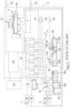
- Fig. 1 represents in a flowchart a direct cooling water treatment circuit of a steel plant for the production of flat products according to the state of the art.
- An exemplary accelerated cooling system 10 with a flow rate of almost 5,000 m 3 /h and a side sweep spray unit 12 (flow rate about 100 m 3 /h) feeds a tank 14 divided into two chambers 14a and 14b separated by a weir 16 which transfers water from the chamber 14b to the chamber 14a.
- the chamber 14b is fed by a tank 18, a cooling tower 20 and a water make-up source 22.
- the cooling tower 20 in turn, is fed by waters deriving directly from the chamber 14a or after cleaning in a filter 24.
- the filter 24 is also served by washing water 26 or backwash air 28.
- the waste from the filter 24 is conveyed to a tank 30 from where the water is subject to drainage or backwash of a scale pit.
- the cooled water chamber 14b feeds only the accelerated cooling systems 10 and the side spray systems 12 (which can be fed in case of need also by a storage/distribution tank 34 which can also feed the chamber 14a ) thus closing the water circuit.
- level gauges are designated with l, pumps with p and agitators with a.
- the flow rates indicated below are just an example and vary with the size of the plant.
- the water treatment circuit includes a second part dedicated to the treatment of water deriving from hot rolling mills for the production of strips at high pressure with flow rates around 3,700 m 3 /h 36 or at low pressure (with flow rates about 240 m 3 /h) 38 and descalers (flow rate of about 350 m 3 /h) 40 and reheating furnaces (flow rate of about 30 m 3 /h) 42 which all feed a tank 44 with a first chamber 44a and a second chamber 44b, and precisely feed the first chamber 44a provided with a crane with a bucket 46 and with an oil separator 48, the surface water (freed from oil and heavy scale) overflows into the chamber 44b, from where it is pumped into a circuit again in the chamber 14a in order to be cleaned a second time or, passing through a two-chamber clarifier 76 with oil
- the tank can also be fed with make-up water 56 or from a tank 58 for storing and dosing conditioning chemicals, while the tank 44 can also be fed with waters coming from a sludge thickener 60.
- the filter 50 is manageable with backwash air 62 and washing water 64, drain water 66 is drained.
- the water of the tank 54 can feed the filter 50 for its backwash with clean water, the dirty water producers 38, 40 and 42 and, with a pump and line dedicated to take into consideration the large flow rate, the user 36; this line provides a blowdown system 68, also available from the line exiting from the tank 14 to feed the cooling water users 10 and 12 or the tank 34.
- the tank 44 can be fed by a polyelectrolyte source 70 or by a tank 72.
- the plant for the production of flat products also includes a water treatment plant for water deriving from indirect cooling, waters that due to the nature of the indirect treatment (for example from reheating furnaces (flow rates about 400 m 3 /h)), hot strip rolling mills (flow rates about 1,300 m 3 /h) and electric motors (with flow rates around 215 m 3 /h) do not require special purifications and can be transferred directly to a cooling tower (equipped with a water make-up service well known to the person skilled in the art, where necessary with filters and brine pits). These indirect cooling waters are not covered by the invention.
- cooling circuits C1 and C2 can be noted, while the invention combines the circuits into a single circuit C putting in series the two groups of producers ( 10, 12 and 36, 38, 40 and 42 ), as represented in figure 2 .
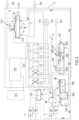
- Fig. 2 represents in a flowchart a direct cooling water treatment plant of a steel plant for the production of flat products according to the invention.
- the elements corresponding to those of the state of the art, as represented in figure 1 have the same reference numbers.
- the sources of heated and contaminated cooling water 10 and 12 no longer directly feed a cooling tower with a double tank and filter system ( 14 and 20 ) as represented in Figure 1 , but they feed a collecting tank 13 from which they reach with different pumps, depending on the required flow rate, the previously illustrated cooling water users 36 (with a flow rate of about 3,700 m 3 /h), 38 and 42 (with a flow rate of about 270 m 3 /h), while the user 40 is fed differently (with a flow rate of about 1,000 m 3 /h), as will be illustrated below.
- the dirty and heated water reaches the bucket system 46 and oil separator 48 with relative tank 44 like in the state of the art ( figure 1 ).
- the first tank 76a envisages the sedimentation of scale and its removal with a bucket 84, a scraper 82 and an oil separator 80 and can be integrated with an addition of polyelectrolyte 70, the water thus cleaned passes through a weir 78 in the chamber 76b, from where it reaches the sand filter system 50 and the cooling tower 52 with a single tank 54 already known from the state of the art ( figure 1 ).
- Make-up 56, drainage 66 and blowdown 68 systems correspond to what is known from the state of the art.
- From the tank 54 the cooled waters can feed the filter 50 for the backwash thereof with clean water, the user 40 or the collecting tank 13, the user 12 or the storage/distribution tank 34.
- the drainage water 60 after an appropriate treatment can return to the tank 76, this treatment involves a collection in a tank from which it is conveyed in a sludge thickener from which it is always introduced into the tank 76 or through a passage through a further tank it continues in a drainage system to eliminate the sludge that must be taken to the landfill.
- Additives can be added to the thickener or to the drainage or dehydration system ( dewatering unit ). This part of the plant is well known to the expert and is not illustrated in more detail.
- the quality, the flow rate and the temperature of the water exiting the users 10 and 12 is therefore suitable for distribution among the users 36, 38, 40 and 42.
- the tanks 13, 34 and 44 and their connections allow compensating for any flow rate imbalances in feeding the users.
- the inlet temperatures in the users 36, 38, 40 and 42 are little influenced by the passage from the classic version to the invention.
- Fig. 3 represents in a flowchart a direct cooling water treatment plant of a steel plant for the production of long products according to the state of the art.
- the quenching 86 and tempering 88 units and those of the fast-finishing block 90 and of the rolling mill and of the reheating furnace 92 are the direct cooling water users in a steel plant for the production of long products.
- the waters exiting from the units 90 and 92 are treated in a tank 94 consisting of two chambers 94a and 94b. In the first chamber 94a the largest scale is removed with a bucket 96, while the water freed of this scale enters the chamber 94b where it is freed of oil with an oil separator 98.
- a tank 100 is used to store and dose a de-oiling product.
- the clean water is conveyed into a longitudinal tank 102 divided into a first chamber 102a and a second chamber 102b, separated by a weir 103.
- a bucket 104 for removing scales
- a scraper 106 for removing scales
- an oil separator 108 In the first chamber 102a there are a bucket 104 for removing scales, a scraper 106 and an oil separator 108.
- the clean water exits the second chamber 102b and passes through a battery of sand filters 110 to reach after filtration two cooling towers 112 that collect the cooled water in a single tank 114.
- the battery of filters 110 envisages a drainage 116 and a backwash system 118.
- the cooled water collected in the tank 114 leaves the same to be conveyed into the battery of filters 110 for the purpose of back washing the filters, to close the cycle to the users 90 and 92 or to be dedicated to a discharge/a blowdown 120 or to reach the other two direct cooling elements 86 and 88 that discharge their dirty and heated cooling water into a collecting tank 122 that directs the water into the chamber 102b of the longitudinal tank 102 from where it travels along the path already described.
- the tank 102 can also be supplied by water from a sludge thickener 124 provided in other parts of the plant.
- the tank 114 can receive conditioning chemicals from a tank 126 or from a make-up water source 128 that also feeds the indirect cooling water cooling plant 130 not detailed of the plant for the production of long products.
- This cooling plant 130 is situated in a circuit with indirect cooling users, such as rolling mills and reheating furnaces etc. 132 without special purification units.
- the flow rates of the users 86, 88, 90 and 92 are by way of example respectively 700-1300 m 3 /h, 600 m 3 /h, about 270 m 3 /h and 600 m 3 /h and the inlet temperature Ti is about 35°C.
- Fig. 4 represents in a flowchart a direct cooling water treatment plant of a steel plant for the production of long products according to the invention.
- the two cooling towers are replaced with only one 212, which also allows to reduce the volume of the respective tank 214.
- the line with relative pump that leads from the tank 214 which in the state of the art, was used to supply the users 90 and 92, which in the example represented, instead, are fed directly from the tank 122, which now partly supplies the users 90 and 92 and the tank 102 which will then lead to feeding the users 86 and 88.
- the reduction of the quantity of water that then reaches the tank 102 and the subsequent cleaning units allows to reduce the number of filters inside the battery of the filters 210.
- the water that derives from the cooling tower 212 now no longer feeds the users 90 and 92, but in addition to the users 86 and 88 also directly the tank 122 to compensate for any deficit due to deficiencies of the quantity deriving from the direct passage from 86 and 88 to 90 and 92.
- the variations with respect to the plant represented in figure 3 have been highlighted with dotted lines and in the case of cancellations of individual elements of the plant also with crosses.
- the example of the state of the art ( figure 3 ) and of the invention ( figure 4 ) always comprise a single water circuit, respectively C ' and C", but the two groups of users 86, 88 and 90, 92 do not reach separately the same longitudinal tank 102, and from there the battery of filters 110 or 210 and cooling tower(s) 112 and 212, but are first connected in series.
- the flow from the tank 122 to the users 90 and 92 is about 870 m 3 /h, while the flow to the tank 102b is reduced by about a third.
- the inlet temperature T i for the users 90 and 92 increases from 35°C to 43°C.
- Fig. 5 represents in a flowchart a direct cooling water treatment plant for accelerated cooling 134, side spray 136 and direct quenching 138 users.
- the three cooling water users discharge the dirty and heated water into a tank 140 that is connected to a double cooling tower 144 with a single-chamber tank 146 that can be fed by a chemical dispenser 148 and by make-up water 150 and to a battery of filters 142.
- the water contained in the tank 146 can be pumped through relative pumps p directly to the user 138 or to the user 136, to the battery of sand filters 146 equipped with an air blower 152 for cleaning them or a storage and distribution tank 154 which, in turn, feeds the user 134 and the tank 146 of the cooling towers 144.
- the backwash water treated in the filters 142 reaches a collecting tank 156 which sends the water to a sludge thickener 158, equipped with a chemical dispenser 159, and which discharges the sludge to a truck 160 or other waste disposal means, while discharging the water that is exiting the thickening into the tank 146 of the cooling towers 144.
- the line connecting the tank 146 to the storage and distribution tank 154 is equipped with a blowdown system 162.
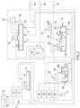
- Fig. 6 represents in a flowchart the direct cooling water treatment plant according to figure 5 modified according to the invention.
- the plant is simplified as the exiting waters do not have to be cleaned separately, but they are transferred to a collecting tank with the possibility of sending them from there directly to a sheet rolling mill, a high-pressure circuit 166 and a low-pressure circuit 168.
- the users 134, 136 and 138 are fed, respectively, by the storage and distribution tank 154 and by a tank 170 that collects the clean and cooled waters from the plant (not represented) that treats the waters exiting the rolling mills 166 and 168.
- This tank is also supplied by chemical dispensers 172, make-up water 174 and is equipped with a blowdown unit 176.
- the tank 170 in addition to supplying the users 136 and 138 also feeds the storage and distribution tank 154, with the possibility of first passing the water through the relative self-cleaning filter units 178, the backwash water 180 can be destined to scale pits.
- Fig. 7 represents in a flowchart the separated direct cooling water treatment plants of a steel plant for the production of long products according to the state of the art.
- the chamber 200a is equipped with an oil separator 202 and can also be fed with water recovered from other parts of the plant 204.
- Backwash waters 206 can be introduced from relative filters into the lines from the aforementioned users. From the oil separator 202, the oil reaches an oil storage 208, while from the chamber 200b the water returns into the tank 192 or it reaches, passing a sand filter 210 with blower 212 and with backwash system 213, the cooling towers 214 that release the cooled water into a longitudinal tank 216. The water can be purified by filtering it with filters 217 equipped with backwash systems 218. The filters can return the filtrate to the tank 216 or send it to the users 186, 188, 190, 184, 182 or to the storage and distribution tank which in turn feeds the user 182 or the tank 216 which can receive chemicals from the dispensers 222.
- a second water treatment plant C6 has three users: an accelerated cooling system 224, a side spray system 226 and a direct quenching system 228 that supply the heated cooling waters in a tank 230, from where they can be sent to the cooling towers 232, through a self-cleaning filter 234 with backwash system 236 to a piezoelectric tank 238, through a self-cleaning filter 234 with backwash system 236 to the users 226 and 228 or to a blowdown 240.
- Make-up water 242 is envisaged for the tank 230 as well as chemical dispensers 244. From the tank 246, the water passes into the tank 230.
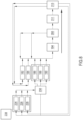
- Fig. 8 represents in a simplified flowchart the union of the two cooling water treatment circuits of figure 7 in a single circuit according to the invention.
- the users 224, 226 and 228 discharge the heated cooling water directly into a tank 230 that feeds a rolling mill 226 and reheating furnaces 228 that discharge their heated waters, like the users 182 and 184 into a scale pit 194, from where they enter a clarifier 200, a battery of filters 210, and cooling towers 214. From the clarifier they can return to the scale pit to repeat the operation provided therein.
- the water cooled in the towers enters the users 182 and 184, the users 224, 226 and 228 or the storage and distribution tank 238 that feeds the users 224 - 228.
Landscapes
- Chemical & Material Sciences (AREA)
- Engineering & Computer Science (AREA)
- Mechanical Engineering (AREA)
- Organic Chemistry (AREA)
- Crystallography & Structural Chemistry (AREA)
- Physics & Mathematics (AREA)
- Materials Engineering (AREA)
- Metallurgy (AREA)
- Thermal Sciences (AREA)
- Life Sciences & Earth Sciences (AREA)
- Hydrology & Water Resources (AREA)
- Environmental & Geological Engineering (AREA)
- Water Supply & Treatment (AREA)
- Oil, Petroleum & Natural Gas (AREA)
- Metal Rolling (AREA)
- Heat Treatment Of Strip Materials And Filament Materials (AREA)
Claims (10)
- Eine Stahlanlage zur Herstellung von Langerzeugnissen, insbesondere von Stäben, Stangen, Profilen, Drähten und dergleichen, oder von Flacherzeugnissen, insbesondere von Bändern, Blechen und dergleichen, umfassend:(a) eine Vielzahl von Maschinen (10, 12, 36, 38, 42; 86, 88, 90, 92; 134, 136, 138, 166, 168; 224, 226, 228, 186, 188, 190), die mit direkten Kühlsystemen ausgestattet und in mindestens eine erste (10, 12; 86, 88; 134, 136, 138; 224, 226, 228) und eine zweite Gruppe (36, 38, 42; 90, 92; 166, 168; 186, 188, 190) von Maschinen aufgeteilt sind, wobei jede Gruppe eine oder mehrere Maschinen umfasst, wobei sich die Gruppen von Maschinen durch die unterschiedliche höhere oder niedrigere Konzentration von Zunder unterscheiden, der in das Kühlwasser freigesetzt wird und sich während der Verwendung jeder Gruppe von Maschinen ansammelt;(b) einen Kreislauf (C, C", C4) zur Behandlung von direktem Kühlwasser, das aus den direkten Kühlsystemen austritt, umfassend eine Vielzahl von Kühlwasserbehandlungsvorrichtungen (44, 76, 50, 52; 94, 102, 210, 212; 194, 200, 211, 213),dadurch gekennzeichnet, dass(i) die direkten Kühlsysteme der beiden Maschinengruppen in Reihe geschaltet sind, wobei die direkten Kühlsysteme der zweiten Maschinengruppe (36, 38, 42; 90, 92; 166, 168; 186, 188, 190), die Kühlwasser mit einer höheren Zunderkonzentration erzeugen, stromabwärts von den direkten Kühlsystemen der ersten Maschinengruppe (10, 12; 86, 88; 134, 136, 138; 224, 226, 228), die Kühlwasser mit einer niedrigeren Zunderkonzentration erzeugen, angeordnet sind, so dass die direkten Kühlsysteme der ersten Maschinengruppe die direkten Kühlsysteme der zweiten Maschinengruppe speisen; und dadurch, dass(ii) der Kreislauf (C, C", C4) zur Behandlung von direktem Kühlwasser stromabwärts der zweiten Maschinengruppe angeordnet ist.
- Die Stahlanlage nach einem der vorhergehenden Ansprüche, dadurch gekennzeichnet, dass zwischen den direkten Kühlsystemen der ersten Gruppe und den direkten Kühlsystemen der zweiten Gruppe mindestens ein Sammelbehälter (13; 122; 164; 230) entlang des Wasserflusses vorgesehen ist.
- Die Stahlanlage nach einem der vorhergehenden Ansprüche, dadurch gekennzeichnet, dass der Kreislauf (C, C", C4) zur Behandlung von direktem Kühlwasser, der stromabwärts von der zweiten Maschinengruppe angeordnet ist, eine Folge von Wasseraufbereitungsvorrichtungen umfasst, die in der folgenden Reihenfolge mindestens einen Tank, vorzugsweise mindestens umfassend zwei Tanks zur Abscheidung von Zunder und/oder Öl (44; 94; 194; 76; 102; 200), wobei der/die Tank(s) vorzugsweise durch ein oder mehrere Wehre (78; 103) in mehrere getrennte Kammern (76a, 76b; 102a, 102b) unterteilt ist/sind, mindestens eine Filtereinheit (50; 210; 211) und mindestens einen Kühlturm (52; 112; 212; 213), der mit mindestens einem Tank (54; 214) zum Sammeln von gekühltem Wasser versehen und mit den direkten Kühlsystemen der ersten Maschinengruppe und/oder, falls vorhanden, mit dem mindestens einen Sammelbehälter (13; 122; 164; 230) verbunden ist.
- Die Stahlanlage nach einem beliebigen der Ansprüche 1 bis 3, dadurch gekennzeichnet, dass die Stahlanlage eine Anlage zur Herstellung von Langerzeugnissen, insbesondere von Stäben, Stangen, Profilen, Drähten und dergleichen ist, und dass die erste Gruppe mindestens eine Maschine umfasst, die aus der Gruppe ausgewählt ist, die aus Abschreckeinheiten und Tempereinheiten besteht, und dass die zweite Gruppe mindestens eine Maschine umfasst, die aus der Gruppe ausgewählt ist, die aus Schnellveredelungsblöcken, Walzwerken und Wiederaufheizöfen besteht.
- Die Stahlanlage nach Anspruch 4, dadurch gekennzeichnet, dass der Sammeltank (122) weiterhin den mindestens einen Zunder- und/oder Ölabscheidebehälter (102), insbesondere einen zweiten Zunder- und/oder Ölabscheidebehälter, vorzugsweise die am weitesten stromabwärts gelegene Kammer (102b) des Behälters, speist.
- Die Stahlanlage nach einem der Ansprüche 1 bis 3, dadurch gekennzeichnet, dass die Stahlanlage eine Anlage zur Herstellung von Flachprodukten, insbesondere von Bändern, Blechen und dergleichen ist, und dass die erste Gruppe von Maschinen mindestens eine Maschine umfasst, die aus der Gruppe ausgewählt ist, die aus beschleunigten Kühleinheiten (10; 134), Seitensprüheinheiten (12; 136), Direktabschreckungseinheiten (138), Laminarkühleinheiten besteht, und dass die zweite Gruppe von Maschinen mindestens eine Maschine umfasst, die aus der Gruppe ausgewählt ist, die aus Warmbandwalzwerken (36; 166; 38; 168) und Wiederaufheizöfen (42) besteht.
- Verfahren zur Behandlung von Direktkühlwässern einer Stahlanlage zur Herstellung von Langerzeugnissen, insbesondere von Stäben, Stangen, Profilen, Drähten und dergleichen, oder von Flacherzeugnissen, insbesondere von Bändern, Blechen und dergleichen, umfassend die folgenden Schritte:(I) Durchführen einer direkten Kühlung in der Stahanlage, was zur Erzeugung von Kühlwässern mit hohem Zundergehalt und Kühlwässern mit geringerem Zundergehalt führt, je nach den Maschinen (10, 12, 36, 38, 42; 86, 88, 90, 92; 134, 136, 138, 166, 168; 224, 226, 228, 186, 188, 190), aus denen die Stahlanlage besteht und die in mindestens zwei Maschinengruppen unterteilt sind, je nach dem Zundergehalt, der von dem von den Maschinengruppen verarbeiteten Produkt in das Kühlwasser abgegeben wird;(II) Leiten des erwärmten Kühlwassers mit geringerem Zundergehalt aus der jeweiligen ersten Maschinengruppe (10, 12; 86, 88; 134, 136, 138; 224, 226, 228) in die zweite Maschinengruppe (36, 38, 42; 90, 92; 166, 168; 186, 188, 190) der Anlage, die zunderreiche Wässer erzeugen, vorzugsweise durch Zwischenspeicherung in einem Sammelbehälter (13; 122; 164; 230);(III) Reinigung des von der zweiten Maschinengruppe (36, 38, 42; 90, 92; 166, 168; 186, 188, 190) erhitzten und verunreinigten Kühlwassers in einer Folge von Wasseraufbereitungsvorrichtungen, die in der folgenden Reihenfolge mindestens einen Behälter, vorzugsweise mindestens zwei Zunder- und/oder Ölabscheidebehälter (44; 94; 194; 76; 102; 200), mindestens eine Filtrationseinheit (50; 210; 211) und mindestens einen Kühlturm (52; 112; 212; 213) umfassen, wobei das Wasser vorzugsweise unter Feuchtkugel-Bedingungen < 26°C auf oder unter 30°C gekühlt wird;(IV) zumindest teilweise Wiedereinleitung des in Schritt (III) gereinigten und gekühlten Wassers in die direkten Kühlsysteme der ersten Maschinengruppe (10, 12; 86, 88; 134, 136, 138; 224, 226, 228) und/oder in den Sammeltank (13; 122; 164; 230), falls vorhanden.
- Verfahren zur Behandlung von direkten Kühlwässern nach Anspruch 7, dadurch gekennzeichnet, dass die Wässer, die die erste Gruppe von Maschinen (10, 12; 86, 88; 134, 136, 138; 224, 226, 228) verlassen, im Falle einer Stahlanlage zur Herstellung von Langerzeugnissen suspendierte Feststoffe ≤ 70 mg/l und im Falle einer Stahlanlage zur Herstellung von Flacherzeugnissen ≤ 50 mg/l enthalten.
- Verfahren zur Behandlung von direkten Kühlwässern nach Anspruch 7 oder 8, dadurch gekennzeichnet, dass die aus der ersten Maschinengruppe (10, 12; 86, 88; 134, 136, 138; 224, 226, 228) austretenden Wässer ein ΔT in Bezug auf die von der zweiten Maschinengruppe (36, 38, 42; 90, 92; 166, 168; 186, 188, 190) geforderten Einlasstemperatur aufweisen, dass < 8 °C im Falle einer Stahlanlage für die Herstellung von Langerzeugnissen und einem ΔT von < 5 °C im Falle einer Stahlanlage für die Herstellung von Flacherzeugnissen entspricht.
- Verfahren zur Behandlung von direkten Kühlwässern nach einem beliebigen der Ansprüche 7 bis 9, dadurch gekennzeichnet, dass die aus der ersten Maschinengruppe (10, 12; 86, 88; 134, 136, 138; 224, 226, 228) austretenden Wässer nur Spuren von Ölen und/oder Fetten, insbesondere ≤ 2 mg/l Öle und/oder Fette, enthalten.
Applications Claiming Priority (2)
| Application Number | Priority Date | Filing Date | Title |
|---|---|---|---|
| IT102022000003797A IT202200003797A1 (it) | 2022-03-01 | 2022-03-01 | Impianto siderurgico con circuito di trattamento acque di raffreddamento diretto e relativo procedimento |
| PCT/IB2023/051836 WO2023166406A1 (en) | 2022-03-01 | 2023-02-28 | Steel plant with direct cooling water treatment circuit and related process |
Publications (3)
| Publication Number | Publication Date |
|---|---|
| EP4479351A1 EP4479351A1 (de) | 2024-12-25 |
| EP4479351C0 EP4479351C0 (de) | 2025-05-21 |
| EP4479351B1 true EP4479351B1 (de) | 2025-05-21 |
Family
ID=81648707
Family Applications (1)
| Application Number | Title | Priority Date | Filing Date |
|---|---|---|---|
| EP23710462.5A Active EP4479351B1 (de) | 2022-03-01 | 2023-02-28 | Stahlwerk mit kreislauf zur direkten kühlwasserbehandlung und zugehöriges verfahren |
Country Status (7)
| Country | Link |
|---|---|
| US (1) | US20250187066A1 (de) |
| EP (1) | EP4479351B1 (de) |
| CN (1) | CN118804900A (de) |
| ES (1) | ES3033219T3 (de) |
| IT (1) | IT202200003797A1 (de) |
| MX (1) | MX2024010658A (de) |
| WO (1) | WO2023166406A1 (de) |
Families Citing this family (1)
| Publication number | Priority date | Publication date | Assignee | Title |
|---|---|---|---|---|
| CN120229799A (zh) * | 2025-04-28 | 2025-07-01 | 福建龙钢新型材料有限公司 | 一种炼钢厂用炼钢废水回收处理循环系统 |
Family Cites Families (3)
| Publication number | Priority date | Publication date | Assignee | Title |
|---|---|---|---|---|
| US5785847A (en) * | 1995-06-07 | 1998-07-28 | Electric Power Research Institute, Inc. | Microwave assisted cleaning and reclamation of industrial wastes |
| WO2014091819A1 (ja) * | 2012-12-10 | 2014-06-19 | 日鉄住金環境株式会社 | 廃水中の懸濁物質の除去処理方法 |
| IT202000007510A1 (it) * | 2020-04-08 | 2021-10-08 | Danieli Off Mecc | Impianto per la produzione di prodotti metallici e metodo di gestione |
-
2022
- 2022-03-01 IT IT102022000003797A patent/IT202200003797A1/it unknown
-
2023
- 2023-02-28 ES ES23710462T patent/ES3033219T3/es active Active
- 2023-02-28 CN CN202380024806.1A patent/CN118804900A/zh active Pending
- 2023-02-28 WO PCT/IB2023/051836 patent/WO2023166406A1/en not_active Ceased
- 2023-02-28 EP EP23710462.5A patent/EP4479351B1/de active Active
- 2023-02-28 US US18/843,081 patent/US20250187066A1/en active Pending
-
2024
- 2024-08-30 MX MX2024010658A patent/MX2024010658A/es unknown
Also Published As
| Publication number | Publication date |
|---|---|
| CN118804900A (zh) | 2024-10-18 |
| WO2023166406A1 (en) | 2023-09-07 |
| EP4479351C0 (de) | 2025-05-21 |
| US20250187066A1 (en) | 2025-06-12 |
| EP4479351A1 (de) | 2024-12-25 |
| ES3033219T3 (en) | 2025-07-31 |
| IT202200003797A1 (it) | 2023-09-01 |
| MX2024010658A (es) | 2024-11-08 |
Similar Documents
| Publication | Publication Date | Title |
|---|---|---|
| US20250187066A1 (en) | Steel plant with direct cooling water treatment circuit and related process | |
| US12576347B2 (en) | Hot rolling mill with separator for mill scale from wastewater | |
| CN112916621A (zh) | 一种热轧浊环水工艺节能控制方法 | |
| EP0513809A2 (de) | Verfahren zur Aufbereitung von in Walzwerksanlagen benutzten Kühl- und/oder Schmiermitteln und hierzu eine Aufbereitungsanlage | |
| JP2013006132A (ja) | 圧延クーラントの循環供給設備 | |
| US6264757B1 (en) | Separating contaminants from continuous from surface cleansing solution during continuous strip steel processing | |
| CN111822519A (zh) | 一种冷连轧机轧辊冷却控制系统 | |
| JP2015231597A (ja) | 鉄鋼系廃水の処理方法 | |
| CN105582735A (zh) | 一种过滤设备及其过滤工艺 | |
| US20240181373A1 (en) | Plant and process for removing suspended solids, oils and greases from cooling water in the steel and metallurgical sector | |
| US12434284B2 (en) | Steel product processing plant with scale separation and recovery system | |
| CN208132558U (zh) | 一种机床切屑液处理装置 | |
| RU2278755C1 (ru) | Устройство для подачи смазочно-охлаждающей жидкости (сож) при дрессировке | |
| CN104083940B (zh) | 一种用于铁精矿浆脱水系统的反清洗系统 | |
| CN213680140U (zh) | 连铸二冷水除油降浊处理装置 | |
| RU2274505C1 (ru) | Способ подачи смазочно-охлаждающей жидкости при дрессировке | |
| CN217163394U (zh) | 用于回收和过滤轧制油的设备 | |
| EP4365266A2 (de) | Geschlossenes gasdichtes system und verfahren zur gewinnung von vermakbaren petrolkoksstücken aus verfestigtem petrolkoks in einer kokstrommeleinheit | |
| CN222627084U (zh) | 一种集中排屑过滤装置 | |
| JP4258001B2 (ja) | 金属表面洗浄防錆システム | |
| CN212559709U (zh) | 一种不锈钢冷轧线脱脂液的高效滤油系统 | |
| CN110921910A (zh) | 一种钢厂浊环水处理装置 | |
| Garbett | Engineering Services at the BHP Rod Mill | |
| CN224128241U (zh) | 一种新型氧化铁皮收集装置 | |
| CN117299837B (zh) | 轧机的油、水供给系统 |
Legal Events
| Date | Code | Title | Description |
|---|---|---|---|
| STAA | Information on the status of an ep patent application or granted ep patent |
Free format text: STATUS: UNKNOWN |
|
| STAA | Information on the status of an ep patent application or granted ep patent |
Free format text: STATUS: THE INTERNATIONAL PUBLICATION HAS BEEN MADE |
|
| PUAI | Public reference made under article 153(3) epc to a published international application that has entered the european phase |
Free format text: ORIGINAL CODE: 0009012 |
|
| STAA | Information on the status of an ep patent application or granted ep patent |
Free format text: STATUS: REQUEST FOR EXAMINATION WAS MADE |
|
| 17P | Request for examination filed |
Effective date: 20240919 |
|
| AK | Designated contracting states |
Kind code of ref document: A1 Designated state(s): AL AT BE BG CH CY CZ DE DK EE ES FI FR GB GR HR HU IE IS IT LI LT LU LV MC ME MK MT NL NO PL PT RO RS SE SI SK SM TR |
|
| GRAP | Despatch of communication of intention to grant a patent |
Free format text: ORIGINAL CODE: EPIDOSNIGR1 |
|
| STAA | Information on the status of an ep patent application or granted ep patent |
Free format text: STATUS: GRANT OF PATENT IS INTENDED |
|
| DAV | Request for validation of the european patent (deleted) | ||
| DAX | Request for extension of the european patent (deleted) | ||
| INTG | Intention to grant announced |
Effective date: 20250131 |
|
| GRAS | Grant fee paid |
Free format text: ORIGINAL CODE: EPIDOSNIGR3 |
|
| GRAA | (expected) grant |
Free format text: ORIGINAL CODE: 0009210 |
|
| STAA | Information on the status of an ep patent application or granted ep patent |
Free format text: STATUS: THE PATENT HAS BEEN GRANTED |
|
| AK | Designated contracting states |
Kind code of ref document: B1 Designated state(s): AL AT BE BG CH CY CZ DE DK EE ES FI FR GB GR HR HU IE IS IT LI LT LU LV MC ME MK MT NL NO PL PT RO RS SE SI SK SM TR |
|
| REG | Reference to a national code |
Ref country code: GB Ref legal event code: FG4D |
|
| REG | Reference to a national code |
Ref country code: CH Ref legal event code: EP |
|
| REG | Reference to a national code |
Ref country code: DE Ref legal event code: R096 Ref document number: 602023003627 Country of ref document: DE |
|
| REG | Reference to a national code |
Ref country code: IE Ref legal event code: FG4D |
|
| U01 | Request for unitary effect filed |
Effective date: 20250617 |
|
| U07 | Unitary effect registered |
Designated state(s): AT BE BG DE DK EE FI FR IT LT LU LV MT NL PT RO SE SI Effective date: 20250626 |
|
| REG | Reference to a national code |
Ref country code: ES Ref legal event code: FG2A Ref document number: 3033219 Country of ref document: ES Kind code of ref document: T3 Effective date: 20250731 |
|
| PG25 | Lapsed in a contracting state [announced via postgrant information from national office to epo] |
Ref country code: NO Free format text: LAPSE BECAUSE OF FAILURE TO SUBMIT A TRANSLATION OF THE DESCRIPTION OR TO PAY THE FEE WITHIN THE PRESCRIBED TIME-LIMIT Effective date: 20250821 Ref country code: GR Free format text: LAPSE BECAUSE OF FAILURE TO SUBMIT A TRANSLATION OF THE DESCRIPTION OR TO PAY THE FEE WITHIN THE PRESCRIBED TIME-LIMIT Effective date: 20250822 |
|
| PG25 | Lapsed in a contracting state [announced via postgrant information from national office to epo] |
Ref country code: PL Free format text: LAPSE BECAUSE OF FAILURE TO SUBMIT A TRANSLATION OF THE DESCRIPTION OR TO PAY THE FEE WITHIN THE PRESCRIBED TIME-LIMIT Effective date: 20250521 |
|
| PG25 | Lapsed in a contracting state [announced via postgrant information from national office to epo] |
Ref country code: HR Free format text: LAPSE BECAUSE OF FAILURE TO SUBMIT A TRANSLATION OF THE DESCRIPTION OR TO PAY THE FEE WITHIN THE PRESCRIBED TIME-LIMIT Effective date: 20250521 |
|
| PG25 | Lapsed in a contracting state [announced via postgrant information from national office to epo] |
Ref country code: RS Free format text: LAPSE BECAUSE OF FAILURE TO SUBMIT A TRANSLATION OF THE DESCRIPTION OR TO PAY THE FEE WITHIN THE PRESCRIBED TIME-LIMIT Effective date: 20250821 |
|
| PG25 | Lapsed in a contracting state [announced via postgrant information from national office to epo] |
Ref country code: IS Free format text: LAPSE BECAUSE OF FAILURE TO SUBMIT A TRANSLATION OF THE DESCRIPTION OR TO PAY THE FEE WITHIN THE PRESCRIBED TIME-LIMIT Effective date: 20250921 |
|
| PG25 | Lapsed in a contracting state [announced via postgrant information from national office to epo] |
Ref country code: SM Free format text: LAPSE BECAUSE OF FAILURE TO SUBMIT A TRANSLATION OF THE DESCRIPTION OR TO PAY THE FEE WITHIN THE PRESCRIBED TIME-LIMIT Effective date: 20250521 |
|
| PG25 | Lapsed in a contracting state [announced via postgrant information from national office to epo] |
Ref country code: CZ Free format text: LAPSE BECAUSE OF FAILURE TO SUBMIT A TRANSLATION OF THE DESCRIPTION OR TO PAY THE FEE WITHIN THE PRESCRIBED TIME-LIMIT Effective date: 20250521 |
|
| PG25 | Lapsed in a contracting state [announced via postgrant information from national office to epo] |
Ref country code: SK Free format text: LAPSE BECAUSE OF FAILURE TO SUBMIT A TRANSLATION OF THE DESCRIPTION OR TO PAY THE FEE WITHIN THE PRESCRIBED TIME-LIMIT Effective date: 20250521 |
|
| PLBE | No opposition filed within time limit |
Free format text: ORIGINAL CODE: 0009261 |
|
| STAA | Information on the status of an ep patent application or granted ep patent |
Free format text: STATUS: NO OPPOSITION FILED WITHIN TIME LIMIT |
|
| REG | Reference to a national code |
Ref country code: CH Ref legal event code: L10 Free format text: ST27 STATUS EVENT CODE: U-0-0-L10-L00 (AS PROVIDED BY THE NATIONAL OFFICE) Effective date: 20260402 |
|
| U20 | Renewal fee for the european patent with unitary effect paid |
Year of fee payment: 4 Effective date: 20260227 |
|
| PGFP | Annual fee paid to national office [announced via postgrant information from national office to epo] |
Ref country code: ES Payment date: 20260302 Year of fee payment: 4 |
|
| PGFP | Annual fee paid to national office [announced via postgrant information from national office to epo] |
Ref country code: TR Payment date: 20260206 Year of fee payment: 4 |
|
| 26N | No opposition filed |
Effective date: 20260224 |