EP4477974A2 - Systeme und verfahren zur steuerung der überhitzung aus einem unterkühler - Google Patents
Systeme und verfahren zur steuerung der überhitzung aus einem unterkühler Download PDFInfo
- Publication number
- EP4477974A2 EP4477974A2 EP24205391.6A EP24205391A EP4477974A2 EP 4477974 A2 EP4477974 A2 EP 4477974A2 EP 24205391 A EP24205391 A EP 24205391A EP 4477974 A2 EP4477974 A2 EP 4477974A2
- Authority
- EP
- European Patent Office
- Prior art keywords
- heat exchanger
- working fluid
- flow
- hvacr
- circuit
- Prior art date
- Legal status (The legal status is an assumption and is not a legal conclusion. Google has not performed a legal analysis and makes no representation as to the accuracy of the status listed.)
- Pending
Links
Images


Classifications
-
- F—MECHANICAL ENGINEERING; LIGHTING; HEATING; WEAPONS; BLASTING
- F25—REFRIGERATION OR COOLING; COMBINED HEATING AND REFRIGERATION SYSTEMS; HEAT PUMP SYSTEMS; MANUFACTURE OR STORAGE OF ICE; LIQUEFACTION SOLIDIFICATION OF GASES
- F25B—REFRIGERATION MACHINES, PLANTS OR SYSTEMS; COMBINED HEATING AND REFRIGERATION SYSTEMS; HEAT PUMP SYSTEMS
- F25B1/00—Compression machines, plants or systems with non-reversible cycle
-
- F—MECHANICAL ENGINEERING; LIGHTING; HEATING; WEAPONS; BLASTING
- F25—REFRIGERATION OR COOLING; COMBINED HEATING AND REFRIGERATION SYSTEMS; HEAT PUMP SYSTEMS; MANUFACTURE OR STORAGE OF ICE; LIQUEFACTION SOLIDIFICATION OF GASES
- F25B—REFRIGERATION MACHINES, PLANTS OR SYSTEMS; COMBINED HEATING AND REFRIGERATION SYSTEMS; HEAT PUMP SYSTEMS
- F25B13/00—Compression machines, plants or systems, with reversible cycle
-
- F—MECHANICAL ENGINEERING; LIGHTING; HEATING; WEAPONS; BLASTING
- F25—REFRIGERATION OR COOLING; COMBINED HEATING AND REFRIGERATION SYSTEMS; HEAT PUMP SYSTEMS; MANUFACTURE OR STORAGE OF ICE; LIQUEFACTION SOLIDIFICATION OF GASES
- F25B—REFRIGERATION MACHINES, PLANTS OR SYSTEMS; COMBINED HEATING AND REFRIGERATION SYSTEMS; HEAT PUMP SYSTEMS
- F25B39/00—Evaporators; Condensers
-
- F—MECHANICAL ENGINEERING; LIGHTING; HEATING; WEAPONS; BLASTING
- F25—REFRIGERATION OR COOLING; COMBINED HEATING AND REFRIGERATION SYSTEMS; HEAT PUMP SYSTEMS; MANUFACTURE OR STORAGE OF ICE; LIQUEFACTION SOLIDIFICATION OF GASES
- F25B—REFRIGERATION MACHINES, PLANTS OR SYSTEMS; COMBINED HEATING AND REFRIGERATION SYSTEMS; HEAT PUMP SYSTEMS
- F25B40/00—Subcoolers, desuperheaters or superheaters
- F25B40/02—Subcoolers
-
- F—MECHANICAL ENGINEERING; LIGHTING; HEATING; WEAPONS; BLASTING
- F25—REFRIGERATION OR COOLING; COMBINED HEATING AND REFRIGERATION SYSTEMS; HEAT PUMP SYSTEMS; MANUFACTURE OR STORAGE OF ICE; LIQUEFACTION SOLIDIFICATION OF GASES
- F25B—REFRIGERATION MACHINES, PLANTS OR SYSTEMS; COMBINED HEATING AND REFRIGERATION SYSTEMS; HEAT PUMP SYSTEMS
- F25B41/00—Fluid-circulation arrangements
- F25B41/20—Disposition of valves, e.g. of on-off valves or flow control valves
- F25B41/26—Disposition of valves, e.g. of on-off valves or flow control valves of fluid flow reversing valves
-
- F—MECHANICAL ENGINEERING; LIGHTING; HEATING; WEAPONS; BLASTING
- F25—REFRIGERATION OR COOLING; COMBINED HEATING AND REFRIGERATION SYSTEMS; HEAT PUMP SYSTEMS; MANUFACTURE OR STORAGE OF ICE; LIQUEFACTION SOLIDIFICATION OF GASES
- F25B—REFRIGERATION MACHINES, PLANTS OR SYSTEMS; COMBINED HEATING AND REFRIGERATION SYSTEMS; HEAT PUMP SYSTEMS
- F25B41/00—Fluid-circulation arrangements
- F25B41/30—Expansion means; Dispositions thereof
-
- F—MECHANICAL ENGINEERING; LIGHTING; HEATING; WEAPONS; BLASTING
- F25—REFRIGERATION OR COOLING; COMBINED HEATING AND REFRIGERATION SYSTEMS; HEAT PUMP SYSTEMS; MANUFACTURE OR STORAGE OF ICE; LIQUEFACTION SOLIDIFICATION OF GASES
- F25B—REFRIGERATION MACHINES, PLANTS OR SYSTEMS; COMBINED HEATING AND REFRIGERATION SYSTEMS; HEAT PUMP SYSTEMS
- F25B49/00—Arrangement or mounting of control or safety devices
- F25B49/02—Arrangement or mounting of control or safety devices for compression type machines, plants or systems
-
- F—MECHANICAL ENGINEERING; LIGHTING; HEATING; WEAPONS; BLASTING
- F25—REFRIGERATION OR COOLING; COMBINED HEATING AND REFRIGERATION SYSTEMS; HEAT PUMP SYSTEMS; MANUFACTURE OR STORAGE OF ICE; LIQUEFACTION SOLIDIFICATION OF GASES
- F25B—REFRIGERATION MACHINES, PLANTS OR SYSTEMS; COMBINED HEATING AND REFRIGERATION SYSTEMS; HEAT PUMP SYSTEMS
- F25B2313/00—Compression machines, plants or systems with reversible cycle not otherwise provided for
- F25B2313/003—Indoor unit with water as a heat sink or heat source
-
- F—MECHANICAL ENGINEERING; LIGHTING; HEATING; WEAPONS; BLASTING
- F25—REFRIGERATION OR COOLING; COMBINED HEATING AND REFRIGERATION SYSTEMS; HEAT PUMP SYSTEMS; MANUFACTURE OR STORAGE OF ICE; LIQUEFACTION SOLIDIFICATION OF GASES
- F25B—REFRIGERATION MACHINES, PLANTS OR SYSTEMS; COMBINED HEATING AND REFRIGERATION SYSTEMS; HEAT PUMP SYSTEMS
- F25B2313/00—Compression machines, plants or systems with reversible cycle not otherwise provided for
- F25B2313/027—Compression machines, plants or systems with reversible cycle not otherwise provided for characterised by the reversing means
- F25B2313/0272—Compression machines, plants or systems with reversible cycle not otherwise provided for characterised by the reversing means using bridge circuits of one-way valves
-
- F—MECHANICAL ENGINEERING; LIGHTING; HEATING; WEAPONS; BLASTING
- F25—REFRIGERATION OR COOLING; COMBINED HEATING AND REFRIGERATION SYSTEMS; HEAT PUMP SYSTEMS; MANUFACTURE OR STORAGE OF ICE; LIQUEFACTION SOLIDIFICATION OF GASES
- F25B—REFRIGERATION MACHINES, PLANTS OR SYSTEMS; COMBINED HEATING AND REFRIGERATION SYSTEMS; HEAT PUMP SYSTEMS
- F25B2313/00—Compression machines, plants or systems with reversible cycle not otherwise provided for
- F25B2313/029—Control issues
- F25B2313/0292—Control issues related to reversing valves
-
- F—MECHANICAL ENGINEERING; LIGHTING; HEATING; WEAPONS; BLASTING
- F25—REFRIGERATION OR COOLING; COMBINED HEATING AND REFRIGERATION SYSTEMS; HEAT PUMP SYSTEMS; MANUFACTURE OR STORAGE OF ICE; LIQUEFACTION SOLIDIFICATION OF GASES
- F25B—REFRIGERATION MACHINES, PLANTS OR SYSTEMS; COMBINED HEATING AND REFRIGERATION SYSTEMS; HEAT PUMP SYSTEMS
- F25B2313/00—Compression machines, plants or systems with reversible cycle not otherwise provided for
- F25B2313/031—Sensor arrangements
- F25B2313/0315—Temperature sensors near the outdoor heat exchanger
-
- F—MECHANICAL ENGINEERING; LIGHTING; HEATING; WEAPONS; BLASTING
- F25—REFRIGERATION OR COOLING; COMBINED HEATING AND REFRIGERATION SYSTEMS; HEAT PUMP SYSTEMS; MANUFACTURE OR STORAGE OF ICE; LIQUEFACTION SOLIDIFICATION OF GASES
- F25B—REFRIGERATION MACHINES, PLANTS OR SYSTEMS; COMBINED HEATING AND REFRIGERATION SYSTEMS; HEAT PUMP SYSTEMS
- F25B2400/00—General features or devices for refrigeration machines, plants or systems, combined heating and refrigeration systems or heat-pump systems, i.e. not limited to a particular subgroup of F25B
- F25B2400/04—Refrigeration circuit bypassing means
- F25B2400/0417—Refrigeration circuit bypassing means for the subcooler
-
- F—MECHANICAL ENGINEERING; LIGHTING; HEATING; WEAPONS; BLASTING
- F25—REFRIGERATION OR COOLING; COMBINED HEATING AND REFRIGERATION SYSTEMS; HEAT PUMP SYSTEMS; MANUFACTURE OR STORAGE OF ICE; LIQUEFACTION SOLIDIFICATION OF GASES
- F25B—REFRIGERATION MACHINES, PLANTS OR SYSTEMS; COMBINED HEATING AND REFRIGERATION SYSTEMS; HEAT PUMP SYSTEMS
- F25B2400/00—General features or devices for refrigeration machines, plants or systems, combined heating and refrigeration systems or heat-pump systems, i.e. not limited to a particular subgroup of F25B
- F25B2400/05—Compression system with heat exchange between particular parts of the system
- F25B2400/054—Compression system with heat exchange between particular parts of the system between the suction tube of the compressor and another part of the cycle
-
- F—MECHANICAL ENGINEERING; LIGHTING; HEATING; WEAPONS; BLASTING
- F25—REFRIGERATION OR COOLING; COMBINED HEATING AND REFRIGERATION SYSTEMS; HEAT PUMP SYSTEMS; MANUFACTURE OR STORAGE OF ICE; LIQUEFACTION SOLIDIFICATION OF GASES
- F25B—REFRIGERATION MACHINES, PLANTS OR SYSTEMS; COMBINED HEATING AND REFRIGERATION SYSTEMS; HEAT PUMP SYSTEMS
- F25B2500/00—Problems to be solved
- F25B2500/08—Exceeding a certain temperature value in a refrigeration component or cycle
-
- F—MECHANICAL ENGINEERING; LIGHTING; HEATING; WEAPONS; BLASTING
- F25—REFRIGERATION OR COOLING; COMBINED HEATING AND REFRIGERATION SYSTEMS; HEAT PUMP SYSTEMS; MANUFACTURE OR STORAGE OF ICE; LIQUEFACTION SOLIDIFICATION OF GASES
- F25B—REFRIGERATION MACHINES, PLANTS OR SYSTEMS; COMBINED HEATING AND REFRIGERATION SYSTEMS; HEAT PUMP SYSTEMS
- F25B2600/00—Control issues
- F25B2600/25—Control of valves
- F25B2600/2501—Bypass valves
-
- F—MECHANICAL ENGINEERING; LIGHTING; HEATING; WEAPONS; BLASTING
- F25—REFRIGERATION OR COOLING; COMBINED HEATING AND REFRIGERATION SYSTEMS; HEAT PUMP SYSTEMS; MANUFACTURE OR STORAGE OF ICE; LIQUEFACTION SOLIDIFICATION OF GASES
- F25B—REFRIGERATION MACHINES, PLANTS OR SYSTEMS; COMBINED HEATING AND REFRIGERATION SYSTEMS; HEAT PUMP SYSTEMS
- F25B2600/00—Control issues
- F25B2600/25—Control of valves
- F25B2600/2507—Flow-diverting valves
-
- F—MECHANICAL ENGINEERING; LIGHTING; HEATING; WEAPONS; BLASTING
- F25—REFRIGERATION OR COOLING; COMBINED HEATING AND REFRIGERATION SYSTEMS; HEAT PUMP SYSTEMS; MANUFACTURE OR STORAGE OF ICE; LIQUEFACTION SOLIDIFICATION OF GASES
- F25B—REFRIGERATION MACHINES, PLANTS OR SYSTEMS; COMBINED HEATING AND REFRIGERATION SYSTEMS; HEAT PUMP SYSTEMS
- F25B2600/00—Control issues
- F25B2600/25—Control of valves
- F25B2600/2515—Flow valves
-
- F—MECHANICAL ENGINEERING; LIGHTING; HEATING; WEAPONS; BLASTING
- F25—REFRIGERATION OR COOLING; COMBINED HEATING AND REFRIGERATION SYSTEMS; HEAT PUMP SYSTEMS; MANUFACTURE OR STORAGE OF ICE; LIQUEFACTION SOLIDIFICATION OF GASES
- F25B—REFRIGERATION MACHINES, PLANTS OR SYSTEMS; COMBINED HEATING AND REFRIGERATION SYSTEMS; HEAT PUMP SYSTEMS
- F25B2700/00—Sensing or detecting of parameters; Sensors therefor
- F25B2700/19—Pressures
- F25B2700/193—Pressures of the compressor
- F25B2700/1933—Suction pressures
-
- F—MECHANICAL ENGINEERING; LIGHTING; HEATING; WEAPONS; BLASTING
- F25—REFRIGERATION OR COOLING; COMBINED HEATING AND REFRIGERATION SYSTEMS; HEAT PUMP SYSTEMS; MANUFACTURE OR STORAGE OF ICE; LIQUEFACTION SOLIDIFICATION OF GASES
- F25B—REFRIGERATION MACHINES, PLANTS OR SYSTEMS; COMBINED HEATING AND REFRIGERATION SYSTEMS; HEAT PUMP SYSTEMS
- F25B2700/00—Sensing or detecting of parameters; Sensors therefor
- F25B2700/21—Temperatures
- F25B2700/2101—Temperatures in a bypass
-
- F—MECHANICAL ENGINEERING; LIGHTING; HEATING; WEAPONS; BLASTING
- F25—REFRIGERATION OR COOLING; COMBINED HEATING AND REFRIGERATION SYSTEMS; HEAT PUMP SYSTEMS; MANUFACTURE OR STORAGE OF ICE; LIQUEFACTION SOLIDIFICATION OF GASES
- F25B—REFRIGERATION MACHINES, PLANTS OR SYSTEMS; COMBINED HEATING AND REFRIGERATION SYSTEMS; HEAT PUMP SYSTEMS
- F25B2700/00—Sensing or detecting of parameters; Sensors therefor
- F25B2700/21—Temperatures
- F25B2700/2103—Temperatures near a heat exchanger
-
- F—MECHANICAL ENGINEERING; LIGHTING; HEATING; WEAPONS; BLASTING
- F25—REFRIGERATION OR COOLING; COMBINED HEATING AND REFRIGERATION SYSTEMS; HEAT PUMP SYSTEMS; MANUFACTURE OR STORAGE OF ICE; LIQUEFACTION SOLIDIFICATION OF GASES
- F25B—REFRIGERATION MACHINES, PLANTS OR SYSTEMS; COMBINED HEATING AND REFRIGERATION SYSTEMS; HEAT PUMP SYSTEMS
- F25B2700/00—Sensing or detecting of parameters; Sensors therefor
- F25B2700/21—Temperatures
- F25B2700/2115—Temperatures of a compressor or the drive means therefor
- F25B2700/21151—Temperatures of a compressor or the drive means therefor at the suction side of the compressor
-
- F—MECHANICAL ENGINEERING; LIGHTING; HEATING; WEAPONS; BLASTING
- F25—REFRIGERATION OR COOLING; COMBINED HEATING AND REFRIGERATION SYSTEMS; HEAT PUMP SYSTEMS; MANUFACTURE OR STORAGE OF ICE; LIQUEFACTION SOLIDIFICATION OF GASES
- F25B—REFRIGERATION MACHINES, PLANTS OR SYSTEMS; COMBINED HEATING AND REFRIGERATION SYSTEMS; HEAT PUMP SYSTEMS
- F25B2700/00—Sensing or detecting of parameters; Sensors therefor
- F25B2700/21—Temperatures
- F25B2700/2117—Temperatures of an evaporator
- F25B2700/21175—Temperatures of an evaporator of the refrigerant at the outlet of the evaporator
Definitions
- HVAC heating, ventilation, air conditioning, and refrigeration
- Subcooling can increase the difference in enthalpy between the condenser and the evaporator in a heating, ventilation, air conditioning, and refrigeration (HVACR) system. This can improve the capacity and efficiency of an HVACR system over the capacity and efficiency of an HVACR system having identical values for the suction and discharge pressure of a compressor included in that HVACR system.
- HVACR heating, ventilation, air conditioning, and refrigeration
- HVAC heating, ventilation, air conditioning, and refrigeration
- the flow of the second working fluid flow is controlled such that the superheat generation does not exceed the threshold superheat value.
- the threshold superheat value is at or about 4° C.
- controlling the flow of the second working fluid flow includes operating a plurality of controllable valves proportionally to allocate flow between a bypass line and the suction line heat exchanger.
- the suction line heat exchanger is a counter-flow heat exchanger wherein the first working fluid flow travels through the suction line heat exchanger in a first direction, and the second working fluid flow travels through the suction line heat exchanger in a second direction, wherein the second direction is opposite the first direction.
- the HVACR circuit is a heat pump circuit
- the first heat exchanger is a heat exchanger receiving working fluid from the expander
- the second heat exchanger is a heat exchanger receiving working fluid from a discharge of the compressor.
- HVACR circuit 100 includes compressor 102, first heat exchanger 104, expansion device 106, second heat exchanger 108, and suction line heat exchanger 110. HVACR circuit further includes fluid line 112, flow director 114, bypass line 116, and return line 118. HVACR circuit 100 also includes first temperature sensor 120 and second temperature sensor 122. HVACR circuit 100 further includes controller 124. HVACR circuit 100 may optionally include a third temperature sensor 126.
- Compressor 102 is a compressor that compresses a working fluid of the HVACR circuit 100.
- Compressor 102 may be any suitable type of compressor for an HVACR system such as, for example, a screw compressor or a scroll compressor.
- Compressor 102 includes suction 128, where the working fluid enters the compressor 102, and discharge 130, where compressed working fluid exits the compressor 102.
- Expansion device 106 is a device configured to reduce the pressure of the working fluid.
- Expansion device 106 is an expander. As a result of reduction in the pressure in the working fluid at expansion device 106, a portion of the working fluid is converted to a gaseous form.
- Expansion device 106 may be, for example, an expansion valve, orifice, or other suitable expander to reduce pressure of a working fluid such as the working fluid.
- expansion device 106 includes multiple orifices. In an embodiment, the multiple orifices of expansion device 106 have different sizes.
- Expansion device 106 may be a controllable expansion device having a variable aperture.
- expansion device 106 is an electronic expansion valve.
- Suction line heat exchanger 110 is a heat exchanger allowing the exchange of heat between two working fluid flows through HVACR circuit 100.
- Suction line heat exchanger 110 may receive a first flow of working fluid from second heat exchanger 108, which then passes to suction 128 of compressor 102 following the exchange of heat within suction line heat exchanger 110.
- Suction line heat exchanger 110 may receive a second flow of working fluid from flow director 114, which then passes to return line 118 following the exchange of heat within suction line heat exchanger 110.
- Suction line heat exchanger 110 may be any suitable form of heat exchanger for exchanging heat between the first and second flows of working fluid.
- suction line heat exchanger 110 is constructed of one or more steel materials.
- suction line heat exchanger 110 does not include copper.
- Fluid line 112 may direct the fluid exiting heat exchanger 104 to flow director 114.
- Flow director 114 allocates the flow from fluid line 112 among the suction line heat exchanger 110 and a bypass line 116.
- Flow director 114 may be any one or more flow controls that are configured to allow a variable amount of the flow exiting heat exchanger 104 to be directed to the suction line heat exchanger 110.
- Flow director 114 may regulate the flow entering suction line heat exchanger 110 based on control by controller 124.
- Bypass line 116 is a fluid line that conveys fluid from flow director 114 to return line 118 without passing through suction line heat exchanger 110.
- Return line 118 is a line that conveys fluid received from suction line heat exchanger 110 and bypass line 116 to the expansion device 106.
- Flow director 114 may be, for example, a three-way valve.
- flow director 114 is a motorized, stepped three-way valve.
- the three-way valve has one input receiving flow from fluid line 112, a first outlet from which fluid passes to suction line heat exchanger 110, and a second outlet from which fluid passes to bypass line 116.
- flow director 114 includes at least two variable-position valves.
- the at least two variable-position valves may be controlled in a complementary fashion, where the extent of opening of each valve is controlled with respect to the others to allocate the flow among suction line heat exchanger 110 and bypass line 116.
- This complementary control may be proportional, for example, having the aperture of the variable-position valve controlling flow to suction line heat exchanger 110 be set to a size proportional to the amount of flow to be directed to the suction line heat exchanger 110 while also having the variable-position valve controlling flow to bypass line 116 be set to a size proportional to the amount of flow to be directed to the bypass line 116.
- Proportional control of valves in flow director 114 may be directed by controller 124.
- flow director 114 includes multiple valves of varying aperture size for each of suction line heat exchanger 110 and bypass line 116 and the allocation of flow is achieved by opening or closing one or more of those multiple valves.
- first temperature sensor 120 is a temperature sensor located directly upstream of or at an inlet of the suction line heat exchanger 110 with respect to the flow of working fluid through the HVACR circuit 100.
- First temperature sensor 120 is a sensor configured to obtain a temperature value, either directly or indirectly.
- First temperature sensor 120 may obtain a first temperature reading that is a temperature of the first working fluid flow prior to the first working fluid flow exchanging heat in the suction line heat exchanger 110.
- the first temperature sensor 120 may be any suitable temperature sensor for measuring a temperature of a working fluid flow prior to that working fluid flow entering the suction line heat exchanger 110.
- First temperature sensor 120 may be operatively coupled to controller 124 such that it can provide a first temperature reading to controller 124.
- the operative coupling may be through any suitable connection to provide the first temperature reading, such as wired or wireless communications.
- second temperature sensor 122 is a temperature sensor located directly downstream of or at an outlet of the suction line heat exchanger 110 with respect to the flow of working fluid through the HVACR circuit 100.
- Second temperature sensor 122 is a sensor configured to obtain a temperature value, either directly or indirectly.
- Second temperature sensor 122 may obtain a second temperature reading that is the temperature of the first working fluid flow subsequent to that working fluid flow exchanging heat at suction line heat exchanger 110.
- Second temperature sensor 122 is upstream of the compressor 102.
- Second temperature sensor 122 may be operatively coupled to controller 124 such that it can provide the second temperature reading to controller 124.
- the operative coupling may be through any suitable connection to provide the second temperature reading, such as wired or wireless communications.
- Controller 124 includes a processor. Controller 124 is operatively coupled to first temperature sensor 120 and second temperature sensor 122. Controller 124 is further operatively coupled to flow director 114 such that the quantity of flow to suction line heat exchanger 110 can be controlled. Controller 124 may be configured to receive a first temperature from the first temperature sensor. Controller 124 may be configured to receive a second temperature from the second temperature sensor. Controller 124 may be configured to determine a superheat generation at the suction line heat exchanger based on the first temperature and the second temperature. In an embodiment, the superheat generation is determined by subtracting the first temperature from the second temperature. Controller 124 may further be configured to control the flow director 114 based on the superheat generation and a threshold superheat value.
- Controller 124 may include a memory, and the memory may be configured to store at least the threshold superheat value.
- the threshold superheat value may be a value of superheat that is permissible for HVACR circuit 100 during operations.
- the threshold superheat value may be based on parameters such as, for example, the design of the HVACR circuit 100, and optionally the amount of working fluid that HVACR circuit 100 has been charged with.
- the threshold superheat value is determined based on a superheat setpoint of the HVACR circuit 100.
- the threshold superheat value may be at or about 4° C.
- the threshold superheat value may be a value selected based on one or more of, for example, avoiding liquid slugging or improving stability at the expansion device 106.
- the threshold superheat value may further be dynamic with the variation in the threshold superheat value being based at least in part on, for example, ambient air temperature, saturated suction temperature, and/or compressor load of compressor 102.
- third temperature sensor 126 may be included in HVACR circuit 100.
- Third temperature sensor 126 may be located along fluid line 112.
- Third temperature sensor 126 may be any suitable temperature sensor for measuring a temperature of the working fluid within fluid line 112.
- Third temperature sensor 126 when included, may measure a third temperature reading that is a temperature of the second working fluid flow that introduced into suction line heat exchanger 110.
- Third temperature sensor 126 when included, may be operatively coupled to controller 124 such that it can provide the third temperature reading to controller 124. The operative coupling may be through any suitable connection to provide the second temperature reading, such as wired or wireless communications.
- the controller 124 may be further configured to determine the amount of flow for flow director 114 to allow into suction line heat exchanger 110 based on the third temperature reading.
- FIG. 2A is a schematic of an HVACR circuit 200 according to an embodiment, wherein the HVACR circuit includes a heat pump in a cooling mode.
- HVACR circuit 200 includes compressor 202, flow reverser 204, first heat exchanger 206 and second heat exchanger 208.
- HVACR circuit 200 optionally includes drier 210.
- HVACR circuit 200 includes fluid line 212 which conveys fluid to flow director 214.
- Flow director 214 allocates flow among bypass line 216 and suction line heat exchanger 218.
- Suction line heat exchanger 218 and bypass line 216 convey fluid to return line 220.
- HVACR circuit 200 further includes expansion device 222.
- HVACR circuit 200 further includes first temperature sensor 224 and second temperature sensor 226.
- HVACR circuit 200 also includes controller 228.
- third temperature sensor 234 may also be included in HVACR circuit 200.
- flow reverser 204 directs working fluid discharged from the discharge of compressor 202 to first heat exchanger 206.
- check valves 236 permit the flow of the working fluid from the first heat exchanger 206 to optional drier 210 or fluid line 212.
- Compressor 202 includes suction 230 and discharge 232.
- Compressor 202 is a compressor that compresses a working fluid of the HVACR circuit 200.
- Compressor 202 may be, for example, any suitable type of compressor for an HVACR system, such as a screw compressor.
- Compressor 202 includes suction 230, where the working fluid enters the compressor 202, and discharge 232, where compressed working fluid exits the compressor 202.
- Flow reverser 204 is a flow control configured to allow the direction of flow through HVACR circuit 200 to be switched between a first direction and a second direction, opposite the first.
- flow reverser 204 is a four-way valve.
- the four-way valve may have a first connection to the discharge 232 of compressor 202, a second connection to first heat exchanger 206, a third connection to the second heat exchanger 208, and a fourth connection to the suction line heat exchanger 218.
- HVACR circuit 200 when HVACR circuit 200 is in a cooling mode, the first connection to discharge 232 is connected to the third connection to second heat exchanger 208, and the second connection to first heat exchanger 206 is connected to the fourth connection to the suction line heat exchanger 218.
- First heat exchanger 206 is a heat exchanger allowing the working fluid to exchange heat as part of a heating or cooling operation of HVACR circuit 200.
- first heat exchanger 206 is an outdoor heat exchanger.
- first heat exchanger 206 receives working fluid compressed by the compressor 202 from flow reverser 204.
- first heat exchanger 206 operates as a condenser allowing the compressed working fluid to reject heat to an ambient environment.
- the working fluid leaving the first heat exchanger 206 then travels to one of optional drier 210 or to flow director 214 via fluid line 212.
- Second heat exchanger 208 is another heat exchanger separate from first heat exchanger 206.
- second heat exchanger 208 creates a heat exchange relationship between the working fluid and a process fluid such as water or air.
- the second heat exchanger 208 receives working fluid from expansion device 222.
- the second heat exchanger functions as an evaporator where the working fluid absorbs heat from the process fluid to provide cooling to a space serviced by an HVACR system including HVACR circuit 200.
- the working fluid exiting the second heat exchanger 208 passes to flow reverser 204.
- HVACR circuit 200 may optionally include drier 210.
- Drier 210 may receive working fluid from the first heat exchanger 206 when HVACR circuit 200 is in the cooling mode as shown in Figure 2A .
- Fluid line 212 conveys the working fluid in HVACR circuit 200 to flow director 214.
- the fluid line 212 may be from drier 210 to flow director 214.
- fluid line 212 may receive working fluid from the first heat exchanger 206 when the HVACR circuit 200 is in the cooling mode as shown in Figure 2A
- Flow director 214 receives working fluid from fluid line 212. Flow director 214 allocates the received working fluid among bypass line 216 and suction line heat exchanger 218. By controlling the amount of working fluid allocated to suction line heat exchanger 218, the superheat and subcooling occurring at suction line heat exchanger 218 can be controlled. The allocation of working fluid among bypass line 216 and suction line heat exchanger 218 may be determined by controller 228, which may direct flow director 214 to allocate the flow according to a command.
- Flow director 214 may be, for example, a three-way valve.
- flow director 214 is a motorized, stepped three-way valve.
- the three-way valve has one input receiving flow from fluid line 212, a first outlet from which fluid passes to suction line heat exchanger 218, and a second outlet from which fluid passes to bypass line 216.
- flow director 214 includes at least two variable-position valves.
- the at least two variable-position valves may be controlled in a complementary fashion, where the extent of opening of each valve is controlled with respect to the others to allocate the flow among suction line heat exchanger 218 and bypass line 216.
- This complementary control may be proportional, for example, having the aperture of the variable-position valve controlling flow to suction line heat exchanger 218 be set to a size proportional to the amount of flow to be directed to the suction line heat exchanger 218 while also having the variable-position valve controlling flow to bypass line 216 be set to a size proportional to the amount of flow to be directed to the bypass line 216.
- Proportional control of valves in flow director 214 may be directed by controller 228.
- flow director 214 includes multiple valves of varying aperture size for each of suction line heat exchanger 218 and bypass line 216 and the allocation of flow is achieved by opening or closing one or more of those multiple valves.
- Bypass line 216 allows fluid from flow director 214 to pass to return line 220 without passing through suction line heat exchanger 218. Bypass line 216 may receive working fluid from flow director 214, depending on the amount of fluid directed to suction line heat exchanger 218.
- Suction line heat exchanger 218 allows a first flow of working fluid from flow reverser 204 to suction 230 of compressor 202 to exchange heat with a second flow of working fluid from flow director 214.
- the first flow of working fluid is a suction gas.
- the second flow of working fluid is a liquid at a relatively higher temperature than the first flow of working fluid.
- heat exchange at suction line heat exchanger superheats the first flow of working fluid and subcools the second flow of working fluid.
- a quantity of fluid included in the second flow of working fluid affects the extent of superheating and/or subcooling occurring as a result of the heat exchange at suction line heat exchanger 218.
- the first flow of working fluid travels through a plurality of tubes and the second flow of working fluid travels through an outer pipe surrounding the plurality of tubes.
- the suction line heat exchanger 218 includes a steel material.
- suction line heat exchanger 218 does not include copper.
- suction line heat exchanger is a counter flow heat exchanger where the first working fluid flow and the second working fluid flow travel in opposite directions through suction line heat exchanger 218.
- Return line 220 receives the working fluid from the bypass line 216 and the second working fluid flow exiting the suction line heat exchanger 218, and conveys the received working fluid to expansion device 222.
- Expansion device 222 is a device configured to reduce the pressure of the working fluid. As a result, a portion of the working fluid is converted to a gaseous form. Expansion device 222 may be, for example, an expansion valve, orifice, or other suitable expander to reduce pressure of a working fluid such as the working fluid. In an embodiment, expansion device 222 includes multiple orifices. In an embodiment, the multiple orifices of expansion device 222 have different sizes. Expansion device 222 may be a controllable expansion device having a variable aperture. In an embodiment, expansion device 222 is an electronic expansion valve.
- First temperature sensor 224 is a temperature sensor located directly upstream of or at an inlet of the suction line heat exchanger 218 with respect to the flow of working fluid through the HVACR circuit 200.
- First temperature sensor 224 may be located between the fourth connection of the flow reverser 204 and the suction line heat exchanger 218.
- First temperature sensor 224 may obtain a first temperature reading that is a temperature of the first working fluid flow prior to the first working fluid flow exchanging heat in the suction line heat exchanger 218.
- the first temperature sensor 224 may be any suitable temperature sensor for measuring a temperature of a working fluid flow prior to that working fluid flow entering the suction line heat exchanger 218.
- First temperature sensor 224 may be operatively coupled to controller 228 such that it can provide a first temperature reading to controller 228. The operative coupling may be through any suitable connection to provide the first temperature reading, such as wired or wireless communications.
- Controller 228 includes a processor. Controller 228 is operatively coupled to first temperature sensor 224 and second temperature sensor 226. Controller 228 is further operatively coupled to flow director 214 such that the quantity of flow to suction line heat exchanger 218 can be controlled. Controller 228 may be configured to receive a first temperature from the first temperature sensor. Controller 228 may be configured to receive a second temperature from the second temperature sensor. Controller 228 may be configured to determine a superheat generation at the suction line heat exchanger based on the first temperature and the second temperature. In an embodiment, the superheat generation is determined by subtracting the first temperature from the second temperature. Controller 228 may further be configured to control the flow director 214 based on the superheat generation and a threshold superheat value.
- third temperature sensor 234 may be included in HVACR circuit 200.
- Third temperature sensor 234 may be located between flow director 214 and suction line heat exchanger 218.
- Third temperature sensor 234 may be any suitable temperature sensor for measuring a temperature of the working fluid between flow director 214 and suction line heat exchanger 218.
- Third temperature sensor 234, when included, may measure a third temperature reading that is a temperature of the second working fluid flow that introduced into suction line heat exchanger 218.
- Third temperature sensor 234, when included, may be operatively coupled to controller 228 such that it can provide the third temperature reading to controller 228. The operative coupling may be through any suitable connection to provide the third temperature reading, such as wired or wireless communications.
- the controller 228 may be further configured to determine the amount of flow for flow director 214 to allow into suction line heat exchanger 218 based on the third temperature reading.
- FIG. 2B is a schematic of an HVACR circuit 200 according to an embodiment, wherein the HVACR circuit includes a heat pump in a heating mode.
- the HVACR circuit 200 includes the components discussed above in Figure 2A .
- flow reverser 204 directs working fluid discharged from the discharge of compressor 202 to second heat exchanger 208.
- check valves 236 permit the flow of the working fluid from the second heat exchanger 208 to optional drier 210 or fluid line 212.
- HVACR circuit 200 When HVACR circuit 200 is in a heating mode as shown in Figure 2B , the first connection to discharge 232 is connected to the second connection to first heat exchanger 206 and the third connection to second heat exchanger 208 is connected to the fourth connection to the suction line heat exchanger 218.
- second heat exchanger 208 receives process fluid compressed by compressor 202 via the flow reverser 204.
- the second heat exchanger 208 operates as a condenser allowing the compressed working fluid to reject heat to the process fluid to provide heating to the space served by the HVACR system including HVACR circuit 200.
- the working fluid leaving the second heat exchanger then travels to one of optional drier 210 or to flow director 214 via fluid line 212.
- fluid line 212 may receive working fluid from the second heat exchanger 208 when the HVACR circuit 200 is in a heating mode as shown in Figure 2B
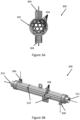
- Figure 3B is a schematic view of the suction line heat exchanger 300 according to an embodiment.
- outer tube 302 is not shown so that tubes 304 and baffles 310 can be shown.
- Inlet 306 and outlet 308 are shown.
- Inlet 306 allows the first flow of the working fluid to enter outer pipe 302.
- the flow of liquid working fluid is directed by baffles 310 as it passes through outer pipe 302 to outlet 308.
- the flow of gaseous working fluid passes from gas inlet 312 to gas outlet 314 via the tubes 314.
- the direction of the flow of gaseous working fluid is opposite the direction of liquid working fluid, as shown in the arrangement of inlets and outlets shown in Figure 3B .
- Figure 4 is a flowchart of a method 400 according to an embodiment.
- Method 400 includes providing a first working fluid flow to a suction line heat exchanger 402 and providing a second working fluid flow to the suction line heat exchanger 404.
- Method 400 further includes receiving a first temperature of the first working fluid flow directly upstream of the suction line heat exchanger 406 and receiving a second temperature of the first working fluid flow directly downstream of the suction line heat exchanger 408.
- Method 400 also includes determining a superheat generation 410 based on the first temperature and the second temperature, and controlling a quantity of flow of the second working fluid flow to the suction line heat exchanger 412 based on the superheat generation and a threshold superheat value.
- a third temperature in the second working fluid flow can be received 414.
- Method 400 includes providing a first working fluid flow to a suction line heat exchanger 402.
- the first working fluid flow may be a flow of a working fluid from a heat exchanger receiving the working fluid from an expansion device towards a suction of a compressor of an HVACR circuit in which method 400 is being performed.
- the first working fluid flow is of a gas at a relatively low temperature.
- the first working fluid flow is of suction gas in the HVACR circuit.
- the first working fluid flow may be from an evaporator used to absorb heat from a process fluid such as air or water.
- the first working fluid flow may be from either an outdoor heat exchanger being used as an evaporator to absorb heat from an ambient environment when in a heating mode, or a heat exchanger being used as an evaporator to absorb heat from a process fluid such as air or water when the HVACR circuit is in a cooling mode.
- Method 400 also includes providing a second working fluid flow to the suction line heat exchanger 404.
- the second working fluid flow may be a flow of working fluid from a heat exchanger that receives working fluid from the discharge of a compressor of the HVACR circuit towards an expansion device of the HVACR circuit.
- the second working fluid flow is from a liquid line in the HVACR circuit.
- the second working fluid flow is a relatively warm liquid flow (i.e. at a temperature higher than that of the first working fluid flow provided at 402).
- the second working fluid flow may be from a condenser used to reject heat to an ambient environment and upstream of an expansion device of the HVACR circuit.
- a first temperature of the first working fluid flow directly upstream of the suction line heat exchanger is received 406.
- the first temperature may be obtained from, for example, a temperature sensor located directly upstream of the suction line heat exchanger. Directly upstream of the suction line heat exchanger is understood as being where no other component of the fluid circuit such as a heat exchanger, compressor, etc. are between the point of measurement and the suction line heat exchanger, aside from the fluid line conveying the working fluid to the suction line heat exchanger.
- the first temperature received at 406 may be measured at an inlet of the suction line heat exchanger.
- the first temperature received at 406 may be measured along a fluid line between the outlet of the heat exchanger receiving working fluid from the expansion device and the inlet of the suction line heat exchanger.
- the first temperature may be communicated to a controller via an operational coupling such as a wired or wireless connection between a temperature sensor taking the measurement and the controller.
- a second temperature of the first working fluid flow directly downstream of the suction line heat exchanger is received at 408.
- Directly downstream of the suction line heat exchanger is understood as being anywhere between the suction line heat exchanger and the next component of the fluid circuit other than a fluid line following the suction line heat exchanger, such as the suction of the compressor.
- the second temperature received at 408 may be obtained from, for example, a temperature sensor.
- the second temperature is a temperature of the first working fluid flow between the outlet of the suction line heat exchanger and a suction of the compressor of the HVACR circuit where method 400 is performed.
- the second temperature is received 408 at the outlet of the suction line heat exchanger.
- the second temperature is received 408 along a fluid line connecting the suction line heat exchanger to the suction of the compressor.
- the second temperature may be communicated to a controller via an operational coupling such as a wired or wireless connection between a temperature sensor taking the measurement and the controller.
- a superheat generation is determined 410 based on the first temperature and the second temperature.
- the superheat generation 410 is a measure of the superheat added to the suction gas by the suction line heat exchanger.
- the superheat generation is determined as the difference between the second temperature received at 408 and the first temperature received at 406.
- the superheat generation may be determined 410 by a controller receiving the first temperature at 406 and the second temperature received at 408, for example by an operative coupling such as a wired or wireless connection between the controller and the sensors measuring the respective first and second temperatures.
- a quantity of flow of the second working fluid flow to the suction line heat exchanger is controlled 412 based on the superheat generation determined at 410 and a threshold superheat value.
- the threshold superheat value may be a value of superheat that is permissible for HVACR circuit during method 400.
- the threshold superheat value may be based on parameters such as, for example, the design of the HVACR circuit and optionally the amount of working fluid that HVACR circuit has been charged with.
- the threshold superheat value is determined based on a superheat setpoint of the HVACR circuit 100.
- the threshold superheat value may be at or about 4° C.
- the threshold superheat value may be a value selected based on one or more of, for example, avoiding liquid slugging or improving stability at an expansion device.
- the threshold superheat value may further be dynamic with the variation in the threshold superheat value being based at least in part on, for example, ambient air temperature, saturated suction temperature, and/or compressor load of a compressor of the HVACR system.
- the quantity of flow of the second working fluid flow may be reduced at 412.
- the quantity of flow of the second working fluid flow may be maintained or increased at 412.
- the quantity of flow of the second working fluid flow and the superheat generation may be used to determine a relationship between the quantity of flow of the second working fluid flow into the suction line heat exchanger and the superheat generation, and this relationship may be used to determine a value for the quantity of flow of the second working fluid flow to provide superheating at or near the threshold superheat value.
- control of the quantity of flow of the second working fluid flow may be achieved through the controller directing a flow director to operate.
- the flow director controlled by the controller to effect control of the quantity of flow of the second working fluid flow at 412 may be one or more flow controls that are configured to control the quantity of fluid allowed to flow into the suction line heat exchanger.
- the flow director may, for example, allocate the flow of fluid between the suction line heat exchanger and a bypass line that allows fluid to continue flow through the HVACR circuit without passing through the suction line heat exchanger.
- the flow director is a three-way valve.
- the flow director is a motorized, stepped three-way valve.
- the flow director has one input, a first outlet from which fluid passes to suction line heat exchanger, and a second outlet from which fluid passes to bypass line.
- the flow director includes at least two variable-position valves.
- the at least two variable-position valves may be controlled in a complementary fashion, where the extent of opening of each valve is controlled with respect to the others to allocate the flow among the suction line heat exchanger and the bypass line.
- the control of the at least two variable-position valves is proportional control.
- the flow director includes multiple valves of varying aperture size for each of the suction line heat exchanger and bypass line and the allocation of flow is achieved by opening or closing one or more of those multiple valves
- a third temperature in the second working fluid flow can be received 414.
- the temperature can be measured upstream of the flow director used to control the quantity of flow of the second working fluid flow to the suction line heat exchanger at 412.
- the third temperature may be used by the controller to further determine the quantity of flow of the second working fluid to be directed to the suction line heat exchanger at 412.
- the third temperature can be a parameter used to determine an expected superheating provided by a quantity of flow of the second working fluid flow into the suction line heat exchanger at 412, and the expected superheating used to provide superheating in an amount below the threshold superheat value.
- the method 400 may be continuous. In an embodiment, the method 400 may iterate by returning from the control of the quantity of the flow of the second working fluid flow at 412 to the measurement of the first temperature at 406, either continuously, at set intervals, or based on triggers such as changes in operating conditions.
- a heating, ventilation, air conditioning, and refrigeration (HVACR) circuit comprising:
- Aspect 2 The HVACR circuit according to aspect 1, wherein the controller is further configured to receive a third temperature of the second working fluid flow prior to entering the flow director or at an inlet of the flow director further control the flow director based on the third temperature.
- Aspect 3 The HVACR circuit according to any of aspects 1-2, wherein the first heat exchanger is an outdoor heat exchanger receiving working fluid from the discharge of the compressor, the second heat exchanger is an evaporator, the first working fluid flow is from the second heat exchanger to the suction of the compressor, and the second working fluid flow is from the first heat exchanger to the expander.
- the first heat exchanger is an outdoor heat exchanger receiving working fluid from the discharge of the compressor
- the second heat exchanger is an evaporator
- the first working fluid flow is from the second heat exchanger to the suction of the compressor
- the second working fluid flow is from the first heat exchanger to the expander.
- HVACR circuit according to any of aspects 1-2, further comprising a flow reverser configured to direct a discharge of the compressor (e.g., working fluid discharged from the discharge of the compressor) to one of the first heat exchanger and the second heat exchanger.
- a flow reverser configured to direct a discharge of the compressor (e.g., working fluid discharged from the discharge of the compressor) to one of the first heat exchanger and the second heat exchanger.
- Aspect 5 The HVACR circuit according to aspect 4, wherein the HVACR circuit is in a cooling mode when the flow reverser directs a discharge of the compressor (e.g., working fluid discharged from the discharge of the compressor) to the first heat exchanger, and is in a heating mode when the flow reverser directs the discharge of the compressor (e.g., working fluid discharged from the discharge of the compressor) to the second heat exchanger.
- a cooling mode when the flow reverser directs a discharge of the compressor
- the discharge of the compressor e.g., working fluid discharged from the discharge of the compressor
- Aspect 6 The HVACR circuit according to aspect 5, wherein when in the cooling mode, the first working fluid flow is from the second heat exchanger to the suction of the compressor, and the second working fluid flow is from the first heat exchanger to the expander.
- Aspect 7 The HVACR circuit according to any of aspects 5-6, wherein when in the heating mode, the first working fluid flow is from the first heat exchanger to the suction of the compressor, and the second working fluid flow is from the second heat exchanger to the expander.
- Aspect 8 The HVACR circuit according to any of aspects 1-7, wherein the suction line heat exchanger is a counter-flow heat exchanger.
- Aspect 9 The HVACR circuit according to any of aspects 1-8, wherein the flow director comprises a stepped three-way valve and a bypass line.
- Aspect 10 The HVACR circuit according to any of aspects 1-8, wherein the flow director comprises a plurality of controllable valves, and wherein the controller is configured to operate the plurality of controllable valves proportionally.
- controlling the flow director based on the superheat generation and a threshold superheat value comprises regulating the second working fluid flow such that the superheat generation is less than the threshold superheat value.
- Aspect 12 The HVACR circuit according to aspect 11, wherein the threshold superheat value is at or about 4° C.
- Aspect 13 The HVACR circuit according to any of aspects 1-12, further comprising a first temperature sensor located upstream of the suction line heat exchanger with respect to the first working fluid flow, and wherein the controller receives the first temperature from the first temperature sensor.
- Aspect 14 The HVACR circuit according to any of aspects 1-13, further comprising a second temperature sensor located between the suction line heat exchanger and the suction of the compressor, and wherein the controller receives the second temperature from the second temperature sensor.
- a method of operating a heating, ventilation, air conditioning, and refrigeration (HVACR) circuit comprising:
- Aspect 16 The method according to aspect 15, wherein the flow (e.g., the quantity of flow) of the second working fluid flow is controlled such that the superheat generation does not exceed the threshold superheat value.
- Aspect 17 The method according to aspect 16, wherein the threshold superheat value is at or about 4° C.
- controlling the flow (e.g., the quantity of flow) of the second working fluid flow comprises directing a portion of the second working fluid flow to a bypass line via a stepped three-way valve.
- controlling the quantity of flow of the second working fluid flow comprises operating a plurality of controllable valves proportionally to allocate flow between a bypass line and the suction line heat exchanger.
- Aspect 20 The method according to any of aspects 15-19, further comprising receiving a third temperature, wherein the third temperature is a temperature of the second working fluid flow, and wherein controlling the quantity of flow of the second working fluid flow is further based on the third temperature.
- Aspect 21 The method according to any of aspects 15-20, wherein the suction line heat exchanger is a counter-flow heat exchanger wherein the first working fluid flow travels through the suction line heat exchanger in a first direction, and the second working fluid flow travels through the suction line heat exchanger in a second direction, wherein the second direction is opposite the first direction.
- Aspect 22 The method according to any of aspects 15-21, wherein the HVACR circuit is a heat pump circuit, the first heat exchanger is a heat exchanger receiving working fluid from the expander, and the second heat exchanger is a heat exchanger receiving working fluid from a discharge of the compressor.
Landscapes
- Engineering & Computer Science (AREA)
- Physics & Mathematics (AREA)
- Mechanical Engineering (AREA)
- Thermal Sciences (AREA)
- General Engineering & Computer Science (AREA)
- Fluid Mechanics (AREA)
- Air Conditioning Control Device (AREA)
- Air-Conditioning For Vehicles (AREA)
Applications Claiming Priority (2)
| Application Number | Priority Date | Filing Date | Title |
|---|---|---|---|
| CN201910704097.7A CN112303944A (zh) | 2019-07-31 | 2019-07-31 | 用于控制来自过冷却器的过热的系统和方法 |
| EP20188891.4A EP3779328B1 (de) | 2019-07-31 | 2020-07-31 | Systeme und verfahren zur steuerung der überhitzung aus einem unterkühler |
Related Parent Applications (1)
| Application Number | Title | Priority Date | Filing Date |
|---|---|---|---|
| EP20188891.4A Division EP3779328B1 (de) | 2019-07-31 | 2020-07-31 | Systeme und verfahren zur steuerung der überhitzung aus einem unterkühler |
Publications (2)
| Publication Number | Publication Date |
|---|---|
| EP4477974A2 true EP4477974A2 (de) | 2024-12-18 |
| EP4477974A3 EP4477974A3 (de) | 2025-03-26 |
Family
ID=71899573
Family Applications (2)
| Application Number | Title | Priority Date | Filing Date |
|---|---|---|---|
| EP20188891.4A Active EP3779328B1 (de) | 2019-07-31 | 2020-07-31 | Systeme und verfahren zur steuerung der überhitzung aus einem unterkühler |
| EP24205391.6A Pending EP4477974A3 (de) | 2019-07-31 | 2020-07-31 | Systeme und verfahren zur steuerung der überhitzung aus einem unterkühler |
Family Applications Before (1)
| Application Number | Title | Priority Date | Filing Date |
|---|---|---|---|
| EP20188891.4A Active EP3779328B1 (de) | 2019-07-31 | 2020-07-31 | Systeme und verfahren zur steuerung der überhitzung aus einem unterkühler |
Country Status (3)
| Country | Link |
|---|---|
| US (3) | US11226140B2 (de) |
| EP (2) | EP3779328B1 (de) |
| CN (1) | CN112303944A (de) |
Families Citing this family (4)
| Publication number | Priority date | Publication date | Assignee | Title |
|---|---|---|---|---|
| CN114909815A (zh) | 2021-02-09 | 2022-08-16 | 特灵国际有限公司 | 可逆热泵 |
| EP4170262A1 (de) | 2021-10-20 | 2023-04-26 | Thermo King Corporation | Wärmepumpe, verfahren zum betrieb und zur simulation |
| DE102023209321A1 (de) * | 2023-09-25 | 2025-03-27 | BSH Hausgeräte GmbH | Kältegerät und Kältemittelkreislauf für ein Kältegerät |
| EP4632291A1 (de) | 2024-04-09 | 2025-10-15 | Rivacold S.R.L. | Dampfkompressionskälteanlage |
Family Cites Families (15)
| Publication number | Priority date | Publication date | Assignee | Title |
|---|---|---|---|---|
| US5341649A (en) | 1993-03-05 | 1994-08-30 | Future Controls, Inc. | Heat transfer system method and apparatus |
| CN101644502B (zh) * | 2005-02-18 | 2011-04-20 | 卡里尔公司 | 制冷回路及用于运行该制冷回路的方法 |
| US8974688B2 (en) | 2009-07-29 | 2015-03-10 | Honeywell International Inc. | Compositions and methods for refrigeration |
| CN103097835B (zh) | 2010-06-30 | 2016-01-20 | 丹福斯有限公司 | 使用过冷值操作蒸汽压缩系统的方法 |
| GB2508614A (en) | 2012-12-04 | 2014-06-11 | Geothermal Boilers Ltd | Refrigerant compositions and heat pump |
| WO2016071947A1 (ja) * | 2014-11-04 | 2016-05-12 | 三菱電機株式会社 | 冷凍サイクル装置及び冷凍サイクル装置の異常検知システム |
| FR3033290B1 (fr) * | 2015-03-04 | 2018-09-14 | Valeo Systemes Thermiques | Circuit de climatisation de vehicule automobile |
| GB2553970B (en) | 2015-04-15 | 2020-08-05 | Mitsubishi Electric Corp | Refrigeration cycle apparatus |
| US10578344B2 (en) | 2015-08-19 | 2020-03-03 | Carrier Corporation | Reversible liquid suction gas heat exchanger |
| DE102016202565A1 (de) | 2016-02-19 | 2017-08-24 | BSH Hausgeräte GmbH | Kältegerät mit mehreren Lagerkammern |
| KR102421874B1 (ko) | 2016-03-25 | 2022-07-18 | 허니웰 인터내셔널 인코포레이티드 | 저gwp 캐스케이드 냉동 시스템 |
| GB201610120D0 (en) * | 2016-06-10 | 2016-07-27 | Eaton Ind Ip Gmbh & Co Kg | Cooling system with adjustable internal heat exchanger |
| EP3568449B1 (de) | 2017-01-13 | 2021-12-22 | Honeywell International Inc. | Kältemittel, wärmetransferzusammensetzungen und verwendung |
| KR20190001142A (ko) * | 2017-06-26 | 2019-01-04 | 엘지전자 주식회사 | 열교환장치 |
| WO2019099960A1 (en) | 2017-11-17 | 2019-05-23 | Honeywell International Inc. | Heat transfer compositions, methods, and systems |
-
2019
- 2019-07-31 CN CN201910704097.7A patent/CN112303944A/zh active Pending
-
2020
- 2020-07-31 US US16/944,847 patent/US11226140B2/en active Active
- 2020-07-31 EP EP20188891.4A patent/EP3779328B1/de active Active
- 2020-07-31 EP EP24205391.6A patent/EP4477974A3/de active Pending
-
2022
- 2022-01-14 US US17/576,073 patent/US11686507B2/en active Active
-
2023
- 2023-06-26 US US18/341,532 patent/US20230332808A1/en active Pending
Also Published As
| Publication number | Publication date |
|---|---|
| US20220136742A1 (en) | 2022-05-05 |
| EP3779328A1 (de) | 2021-02-17 |
| US11686507B2 (en) | 2023-06-27 |
| EP3779328B1 (de) | 2024-10-09 |
| US20210055020A1 (en) | 2021-02-25 |
| US20230332808A1 (en) | 2023-10-19 |
| US11226140B2 (en) | 2022-01-18 |
| CN112303944A (zh) | 2021-02-02 |
| EP4477974A3 (de) | 2025-03-26 |
Similar Documents
| Publication | Publication Date | Title |
|---|---|---|
| US11686507B2 (en) | Systems and methods for control of superheat from a subcooler | |
| EP2752627B1 (de) | Kühlvorrichtung | |
| EP3062031B1 (de) | Klimaanlage | |
| US8353173B2 (en) | Refrigerating cycle apparatus and operation control method therefor | |
| JP6895901B2 (ja) | 空気調和装置 | |
| EP2128541A1 (de) | Kühlvorrichtung | |
| US11906191B2 (en) | Air-conditioning apparatus | |
| GB2569898A (en) | Air conditioner | |
| WO2013145006A1 (ja) | 空気調和装置 | |
| JPS645227B2 (de) | ||
| JP5979112B2 (ja) | 冷凍装置 | |
| KR100569554B1 (ko) | 공기 조화 장치의 열원 유닛 및 공기 조화 장치 | |
| EP3680565B1 (de) | Klimatisierungsvorrichtung | |
| JPWO2015097787A1 (ja) | 空気調和装置 | |
| CN109312971A (zh) | 制冷循环装置以及用于该制冷循环装置的室外热交换器 | |
| CN109312961B (zh) | 制冷装置的热源机组 | |
| JP7386613B2 (ja) | 熱交換器およびそれを備えた空気調和機 | |
| US12044451B2 (en) | System and method for superheat regulation and efficiency improvement | |
| US20260036343A1 (en) | Hvac cascade heat pump | |
| US12320566B2 (en) | Suction gas heat exchanger control and utilization | |
| WO2024166276A1 (ja) | 空気調和装置 | |
| KR101403777B1 (ko) | 공기조화기의 과냉각 시스템 | |
| JPWO2013145006A1 (ja) | 空気調和装置 |
Legal Events
| Date | Code | Title | Description |
|---|---|---|---|
| PUAI | Public reference made under article 153(3) epc to a published international application that has entered the european phase |
Free format text: ORIGINAL CODE: 0009012 |
|
| STAA | Information on the status of an ep patent application or granted ep patent |
Free format text: STATUS: THE APPLICATION HAS BEEN PUBLISHED |
|
| AC | Divisional application: reference to earlier application |
Ref document number: 3779328 Country of ref document: EP Kind code of ref document: P |
|
| AK | Designated contracting states |
Kind code of ref document: A2 Designated state(s): AL AT BE BG CH CY CZ DE DK EE ES FI FR GB GR HR HU IE IS IT LI LT LU LV MC MK MT NL NO PL PT RO RS SE SI SK SM TR |
|
| REG | Reference to a national code |
Ref country code: DE Ref legal event code: R079 Free format text: PREVIOUS MAIN CLASS: F25B0049020000 Ipc: F25B0040000000 |
|
| PUAL | Search report despatched |
Free format text: ORIGINAL CODE: 0009013 |
|
| AK | Designated contracting states |
Kind code of ref document: A3 Designated state(s): AL AT BE BG CH CY CZ DE DK EE ES FI FR GB GR HR HU IE IS IT LI LT LU LV MC MK MT NL NO PL PT RO RS SE SI SK SM TR |
|
| RIC1 | Information provided on ipc code assigned before grant |
Ipc: F25B 49/02 20060101ALI20250217BHEP Ipc: F25B 40/00 20060101AFI20250217BHEP |
|
| STAA | Information on the status of an ep patent application or granted ep patent |
Free format text: STATUS: REQUEST FOR EXAMINATION WAS MADE |
|
| 17P | Request for examination filed |
Effective date: 20250926 |