EP4477930A2 - Tube flexible pour le transport de matériaux abrasifs et procédé de fabrication associé - Google Patents
Tube flexible pour le transport de matériaux abrasifs et procédé de fabrication associé Download PDFInfo
- Publication number
- EP4477930A2 EP4477930A2 EP24210075.8A EP24210075A EP4477930A2 EP 4477930 A2 EP4477930 A2 EP 4477930A2 EP 24210075 A EP24210075 A EP 24210075A EP 4477930 A2 EP4477930 A2 EP 4477930A2
- Authority
- EP
- European Patent Office
- Prior art keywords
- flexible tube
- side wall
- circular disks
- elastomeric matrix
- tube
- Prior art date
- Legal status (The legal status is an assumption and is not a legal conclusion. Google has not performed a legal analysis and makes no representation as to the accuracy of the status listed.)
- Granted
Links
Images

Classifications
-
- B—PERFORMING OPERATIONS; TRANSPORTING
- B29—WORKING OF PLASTICS; WORKING OF SUBSTANCES IN A PLASTIC STATE IN GENERAL
- B29D—PRODUCING PARTICULAR ARTICLES FROM PLASTICS OR FROM SUBSTANCES IN A PLASTIC STATE
- B29D23/00—Producing tubular articles
- B29D23/001—Pipes; Pipe joints
-
- F—MECHANICAL ENGINEERING; LIGHTING; HEATING; WEAPONS; BLASTING
- F16—ENGINEERING ELEMENTS AND UNITS; GENERAL MEASURES FOR PRODUCING AND MAINTAINING EFFECTIVE FUNCTIONING OF MACHINES OR INSTALLATIONS; THERMAL INSULATION IN GENERAL
- F16L—PIPES; JOINTS OR FITTINGS FOR PIPES; SUPPORTS FOR PIPES, CABLES OR PROTECTIVE TUBING; MEANS FOR THERMAL INSULATION IN GENERAL
- F16L11/00—Hoses, i.e. flexible pipes
- F16L11/04—Hoses, i.e. flexible pipes made of rubber or flexible plastics
- F16L11/08—Hoses, i.e. flexible pipes made of rubber or flexible plastics with reinforcements embedded in the wall
-
- F—MECHANICAL ENGINEERING; LIGHTING; HEATING; WEAPONS; BLASTING
- F16—ENGINEERING ELEMENTS AND UNITS; GENERAL MEASURES FOR PRODUCING AND MAINTAINING EFFECTIVE FUNCTIONING OF MACHINES OR INSTALLATIONS; THERMAL INSULATION IN GENERAL
- F16L—PIPES; JOINTS OR FITTINGS FOR PIPES; SUPPORTS FOR PIPES, CABLES OR PROTECTIVE TUBING; MEANS FOR THERMAL INSULATION IN GENERAL
- F16L11/00—Hoses, i.e. flexible pipes
- F16L11/04—Hoses, i.e. flexible pipes made of rubber or flexible plastics
- F16L11/08—Hoses, i.e. flexible pipes made of rubber or flexible plastics with reinforcements embedded in the wall
- F16L11/085—Hoses, i.e. flexible pipes made of rubber or flexible plastics with reinforcements embedded in the wall comprising one or more braided layers
-
- F—MECHANICAL ENGINEERING; LIGHTING; HEATING; WEAPONS; BLASTING
- F16—ENGINEERING ELEMENTS AND UNITS; GENERAL MEASURES FOR PRODUCING AND MAINTAINING EFFECTIVE FUNCTIONING OF MACHINES OR INSTALLATIONS; THERMAL INSULATION IN GENERAL
- F16L—PIPES; JOINTS OR FITTINGS FOR PIPES; SUPPORTS FOR PIPES, CABLES OR PROTECTIVE TUBING; MEANS FOR THERMAL INSULATION IN GENERAL
- F16L11/00—Hoses, i.e. flexible pipes
- F16L11/04—Hoses, i.e. flexible pipes made of rubber or flexible plastics
- F16L11/08—Hoses, i.e. flexible pipes made of rubber or flexible plastics with reinforcements embedded in the wall
- F16L11/088—Hoses, i.e. flexible pipes made of rubber or flexible plastics with reinforcements embedded in the wall comprising a combination of one or more layers of a helically wound cord or wire with one or more braided layers
-
- F—MECHANICAL ENGINEERING; LIGHTING; HEATING; WEAPONS; BLASTING
- F16—ENGINEERING ELEMENTS AND UNITS; GENERAL MEASURES FOR PRODUCING AND MAINTAINING EFFECTIVE FUNCTIONING OF MACHINES OR INSTALLATIONS; THERMAL INSULATION IN GENERAL
- F16L—PIPES; JOINTS OR FITTINGS FOR PIPES; SUPPORTS FOR PIPES, CABLES OR PROTECTIVE TUBING; MEANS FOR THERMAL INSULATION IN GENERAL
- F16L11/00—Hoses, i.e. flexible pipes
- F16L11/04—Hoses, i.e. flexible pipes made of rubber or flexible plastics
- F16L11/11—Hoses, i.e. flexible pipes made of rubber or flexible plastics with corrugated wall
- F16L11/112—Hoses, i.e. flexible pipes made of rubber or flexible plastics with corrugated wall having reinforcements embedded in the wall
-
- F—MECHANICAL ENGINEERING; LIGHTING; HEATING; WEAPONS; BLASTING
- F16—ENGINEERING ELEMENTS AND UNITS; GENERAL MEASURES FOR PRODUCING AND MAINTAINING EFFECTIVE FUNCTIONING OF MACHINES OR INSTALLATIONS; THERMAL INSULATION IN GENERAL
- F16L—PIPES; JOINTS OR FITTINGS FOR PIPES; SUPPORTS FOR PIPES, CABLES OR PROTECTIVE TUBING; MEANS FOR THERMAL INSULATION IN GENERAL
- F16L11/00—Hoses, i.e. flexible pipes
- F16L11/04—Hoses, i.e. flexible pipes made of rubber or flexible plastics
- F16L11/11—Hoses, i.e. flexible pipes made of rubber or flexible plastics with corrugated wall
- F16L11/118—Hoses, i.e. flexible pipes made of rubber or flexible plastics with corrugated wall having arrangements for particular purposes, e.g. electrically conducting
-
- F—MECHANICAL ENGINEERING; LIGHTING; HEATING; WEAPONS; BLASTING
- F16—ENGINEERING ELEMENTS AND UNITS; GENERAL MEASURES FOR PRODUCING AND MAINTAINING EFFECTIVE FUNCTIONING OF MACHINES OR INSTALLATIONS; THERMAL INSULATION IN GENERAL
- F16L—PIPES; JOINTS OR FITTINGS FOR PIPES; SUPPORTS FOR PIPES, CABLES OR PROTECTIVE TUBING; MEANS FOR THERMAL INSULATION IN GENERAL
- F16L11/00—Hoses, i.e. flexible pipes
- F16L11/04—Hoses, i.e. flexible pipes made of rubber or flexible plastics
- F16L11/11—Hoses, i.e. flexible pipes made of rubber or flexible plastics with corrugated wall
- F16L11/118—Hoses, i.e. flexible pipes made of rubber or flexible plastics with corrugated wall having arrangements for particular purposes, e.g. electrically conducting
- F16L11/1185—Hoses, i.e. flexible pipes made of rubber or flexible plastics with corrugated wall having arrangements for particular purposes, e.g. electrically conducting electrically conducting
-
- F—MECHANICAL ENGINEERING; LIGHTING; HEATING; WEAPONS; BLASTING
- F16—ENGINEERING ELEMENTS AND UNITS; GENERAL MEASURES FOR PRODUCING AND MAINTAINING EFFECTIVE FUNCTIONING OF MACHINES OR INSTALLATIONS; THERMAL INSULATION IN GENERAL
- F16L—PIPES; JOINTS OR FITTINGS FOR PIPES; SUPPORTS FOR PIPES, CABLES OR PROTECTIVE TUBING; MEANS FOR THERMAL INSULATION IN GENERAL
- F16L11/00—Hoses, i.e. flexible pipes
- F16L11/04—Hoses, i.e. flexible pipes made of rubber or flexible plastics
- F16L11/12—Hoses, i.e. flexible pipes made of rubber or flexible plastics with arrangements for particular purposes, e.g. specially profiled, with protecting layer, heated, electrically conducting
-
- F—MECHANICAL ENGINEERING; LIGHTING; HEATING; WEAPONS; BLASTING
- F16—ENGINEERING ELEMENTS AND UNITS; GENERAL MEASURES FOR PRODUCING AND MAINTAINING EFFECTIVE FUNCTIONING OF MACHINES OR INSTALLATIONS; THERMAL INSULATION IN GENERAL
- F16L—PIPES; JOINTS OR FITTINGS FOR PIPES; SUPPORTS FOR PIPES, CABLES OR PROTECTIVE TUBING; MEANS FOR THERMAL INSULATION IN GENERAL
- F16L11/00—Hoses, i.e. flexible pipes
- F16L11/04—Hoses, i.e. flexible pipes made of rubber or flexible plastics
- F16L11/12—Hoses, i.e. flexible pipes made of rubber or flexible plastics with arrangements for particular purposes, e.g. specially profiled, with protecting layer, heated, electrically conducting
- F16L11/122—Hoses provided with integrated fixing means, e.g. hooks
-
- F—MECHANICAL ENGINEERING; LIGHTING; HEATING; WEAPONS; BLASTING
- F16—ENGINEERING ELEMENTS AND UNITS; GENERAL MEASURES FOR PRODUCING AND MAINTAINING EFFECTIVE FUNCTIONING OF MACHINES OR INSTALLATIONS; THERMAL INSULATION IN GENERAL
- F16L—PIPES; JOINTS OR FITTINGS FOR PIPES; SUPPORTS FOR PIPES, CABLES OR PROTECTIVE TUBING; MEANS FOR THERMAL INSULATION IN GENERAL
- F16L23/00—Flanged joints
- F16L23/02—Flanged joints the flanges being connected by members tensioned axially
- F16L23/032—Flanged joints the flanges being connected by members tensioned axially characterised by the shape or composition of the flanges
-
- F—MECHANICAL ENGINEERING; LIGHTING; HEATING; WEAPONS; BLASTING
- F16—ENGINEERING ELEMENTS AND UNITS; GENERAL MEASURES FOR PRODUCING AND MAINTAINING EFFECTIVE FUNCTIONING OF MACHINES OR INSTALLATIONS; THERMAL INSULATION IN GENERAL
- F16L—PIPES; JOINTS OR FITTINGS FOR PIPES; SUPPORTS FOR PIPES, CABLES OR PROTECTIVE TUBING; MEANS FOR THERMAL INSULATION IN GENERAL
- F16L33/00—Arrangements for connecting hoses to rigid members; Rigid hose-connectors, i.e. single members engaging both hoses
- F16L33/18—Arrangements for connecting hoses to rigid members; Rigid hose-connectors, i.e. single members engaging both hoses characterised by the use of additional sealing means
-
- F—MECHANICAL ENGINEERING; LIGHTING; HEATING; WEAPONS; BLASTING
- F16—ENGINEERING ELEMENTS AND UNITS; GENERAL MEASURES FOR PRODUCING AND MAINTAINING EFFECTIVE FUNCTIONING OF MACHINES OR INSTALLATIONS; THERMAL INSULATION IN GENERAL
- F16L—PIPES; JOINTS OR FITTINGS FOR PIPES; SUPPORTS FOR PIPES, CABLES OR PROTECTIVE TUBING; MEANS FOR THERMAL INSULATION IN GENERAL
- F16L57/00—Protection of pipes or objects of similar shape against external or internal damage or wear
- F16L57/06—Protection of pipes or objects of similar shape against external or internal damage or wear against wear
Definitions
- the present invention relates to a flexible tube for conveying abrasive materials and the related manufacturing method.
- said abrasive materials are moved by means of plastic or elastomeric tubes which are fluidly connected to suction or delivery systems.
- plastic or rubber tubes equipped, at the inner side walls thereof, with protective elements such as spheres made of a highly hard material, as in case of ceramic materials, which are at least partially embedded in the main rubber structure forming the thickness of the conveying tube. It is apparent that embedding spheres inside the polymer matrix of the tube creates a solid, long-lasting fastening of the spheres with respect to the inner side walls of the tube itself.
- the spherical bodies have ends that interfere with and limit the passage lumen of the hollow tube: on the one hand, such ends reduce the effective flow rate of the tube, and on the other hand, they tend to be damaged and removed over time because of the continuous and violent impacts to which they are subjected by the bodies passing inside the tube. Therefore, even if such solutions require longer maintenance intervals as compared to the mentioned solutions of the prior art, they still imply non-negligible maintenance costs. It has been seen, for example, that by virtue of such spheres made of ceramic material it is possible to increase the maintenance intervals up to two or at the most three weeks.
- curvature limits can be unacceptable drawbacks in some specific applications in which the available spaces impose particularly small radii of curvature, which are not practicable due to the reasons set out above. Solutions according to prior art are disclosed by CA 2886739 A1 , WO 2010/150621 A1 and WO 2008/119395 A1 .
- reference numeral 4 indicates an overall view of a flexible tube for conveying abrasive materials.
- a 'flexible' tube means a tube that can be easily laid and reversibly bent along a predetermined path without the aid of any bending tools; flexibility does not necessarily imply compressibility, i.e., modification of the geometry of the inner passage lumen of the tube, which remains substantially unvaried, typically with a circular section, throughout the laying and operating conditions of the flexible conveying tube.
- Abrasive materials mean any type of material that is substantially hard and/or cutting and/or sharp, such as production waste, scraps.
- the flexible tube 4 comprises a tubular body 8 extending along a main extension axis Z-Z.
- the main extension axis can be rectilinear but also curvilinear according to the final configuration of the tube: in this latter case, the main extension axis Z-Z will be assimilated to the segment tangential to the corresponding curvilinear abscissa.
- the main extension axis Z-Z will be assimilated to the segment tangential to the corresponding curvilinear abscissa.
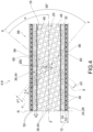
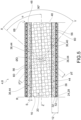
- the tubular body 8 has a thickness 12 extending from an inner side wall 16, which delimits an inner cavity 20 used for transporting abrasive material, to an outer side wall 24, opposite to said inner side wall 16 along a radial direction R-R, perpendicular and incident to said main extension axis Z-Z.
- the tubular body 8 comprises a covering layer 28 made of synthetic rubber at the outer side wall 24.
- said covering layer 28 made of synthetic rubber is made of an NR/BR mixture and/or SBR, EPDM, CR mixtures.
- said tubular body 8 comprises an elastomeric matrix 32, in which there are at least partially embedded circular disks 36 having a diameter D and flat faces, made of ceramic material.
- Said circular disks 36 act as a partial anti-abrasive coating of the inner side wall 16.
- the circular disks 36 increase the resistance of the inner side wall 16 when an abrasive material passes inside the cavity 20.
- Said circular disks 36 have a first flat face 40 directly facing said inner cavity 20 so as to at least partially form the inner side wall 16 and a second flat face 44 embedded in the elastomeric matrix 32.
- the circular disks 36 are arranged on rows parallel to a first laying direction X-X with a first constant pitch p1, and on rows parallel to a second laying direction Y-Y, with a second constant pitch p2, said laying directions X-X, Y-Y being perpendicular to each other.
- the first pitch p1 and the diameter D of the circular disks 36 are linked by the following relationship: 1 ⁇ p1/D ⁇ 1.5.
- the second pitch p2 and the diameter D of the circular disks 36 are linked by the following relationship: 1 ⁇ p2/D ⁇ 1.5.
- the circular disks 36 are arranged so that 30° ⁇ 60°, ⁇ being the angle identified between the first laying direction X-X and said main extension axis Z-Z of the tube 4.
- the circular disks 36 are arranged so that 0 ⁇ f ⁇ p1/2, f being equal to the distance, measured parallel to said first laying direction X-X, between the centres of two disks 36 arranged on rows adjacent to each other and parallel to the second laying direction Y-Y.
- the circular disks 36 can have several dimensions; preferably the circular disks 36 have a diameter D between 3 mm and 20 mm.
- said circular disks 36 have a thickness S between 1 mm and 10 mm, the thickness S being equal to the distance between the first flat face 40 and the second flat face 44.
- the circular disks 36 are made of at least 92% Al2O3 sintered alumina; preferably said circular disks 36 have a Rockwell hardness (HRA) equal to at least 80.
- HRA Rockwell hardness
- said circular disks 36 are treated in advance with a solution cycle in order to improve the adhesion with said elastomeric matrix 32.
- Said elastomeric matrix 32 comprises a portion of anti-abrasive rubber 48 directly facing the inner cavity 20.
- the inner side wall 16 is thus delimited by the first flat faces 40 of the circular disks 36 and by the portion of anti-abrasive rubber 48 filling the gaps between the first flat faces 40 of the circular disks 36 adjacent to one another.
- Said elastomeric matrix 32 can comprise an NR/BR SBR and/or EPDM mixture.
- At least one reinforcement layer 52 is embedded inside the elastomeric matrix 32, comprising synthetic fabrics embedded in SBR, NR/BR and/or EPDM mixture.
- said synthetic fabrics comprise cellulose and/or polyester and/or aramid and/or polyvinyl alcohol and/or polyamide, with titres between 940 dtex and 17600 dtex.
- said reinforcement layer 52 comprises a steel spiral 56 of a diameter between 1 mm and 14 mm.
- At least one copper braid 60 is embedded inside the elastomeric matrix 32, for the dissipation of the electrostatic charges; for example, the copper braid consists of 60-120 tinned copper wires of diameter 0.1.
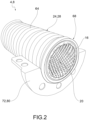
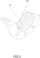
- the flexible tube 4 has a corrugated outer profile 64 and, at at least one axial end 68 of the flexible tube 4, at least one flange 72 having a corrugated inner profile 76 corresponding to said outer profile of the flexible tube is applied, so as to obtain a shape coupling with the latter.
- said flange 72 comprises a pair of mirrored half-shells 80 clamped to each other on the outer side wall 24 of the flexible tube 4 and at least one lip seal 84 at said axial end of the tube 4.
- said lip seal 84 is at least partially interposed between the half-shells 80 and the outer side wall 24 of the tube 4.
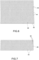
- the method for making a flexible tube 4 according to the invention comprises the steps of arranging and constraining, on a plastic film 88, a plurality of circular disks 36 according to the pattern described above ( figure 6 ) . It is to be specified that, following the use of the tube, with the passage of the abrasive material, such a plastic film 88 is removed; therefore, the purpose of said plastic film 88 consists in allowing/facilitating the correct arrangement of the circular disks 36 in the inner side wall 16 of the flexible tube 4.
- a first layer of elastomeric matrix 32 is spread onto the previously rolled plastic film 88, so as to embed the circular disks 36 on the side of the second flat faces 44 of the circular disks themselves.
- At least a second layer of elastomeric matrix 32 is spread, so as to completely incorporate the circular disks 36 and reinforce the overall structure of the tube 4.
- possible reinforcement layers 52 are applied, comprising synthetic fabrics made of SBR, NR/BR and/or EPDM mixture, and/or a steel spiral 56 and/or a copper braid 60 for the dissipation of the electrostatic charges.
- a covering layer 28 of NR/BR or SBR or EPDM or CR mixture is applied.
- the present invention allows overcoming the drawbacks of the prior art.
- the flexible conveying tube according to the present invention is capable of transporting abrasive materials moved by suction or delivery without undergoing deterioration due to abrasion.
- the solution according to the present invention has significantly longer maintenance intervals compared to the above mentioned solutions of the prior art.
- the present invention allows transporting products that require the absolute absence of electric charges, due to the provision of copper braids that can dissipate said electrostatic charges.
- the solution according to the present invention allows making great tube curvatures, because the ceramic disks do not protrude into the passage lumen of the tube itself. Moreover, the particular geometry and arrangement of such reinforcement disks ensures excellent flexibility for the tube itself.
Landscapes
- Engineering & Computer Science (AREA)
- General Engineering & Computer Science (AREA)
- Mechanical Engineering (AREA)
- Rigid Pipes And Flexible Pipes (AREA)
- Chemical & Material Sciences (AREA)
- Ceramic Engineering (AREA)
Applications Claiming Priority (2)
| Application Number | Priority Date | Filing Date | Title |
|---|---|---|---|
| IT102023000002472A IT202300002472A1 (it) | 2023-02-14 | 2023-02-14 | Tubo flessibile per il convogliamento di materiali abrasivi e relativo metodo di realizzazione |
| EP24153626.7A EP4417858B1 (fr) | 2023-02-14 | 2024-01-24 | Tube flexible pour le transport de matériaux abrasifs et procédé de fabrication associé |
Related Parent Applications (2)
| Application Number | Title | Priority Date | Filing Date |
|---|---|---|---|
| EP24153626.7A Division-Into EP4417858B1 (fr) | 2023-02-14 | 2024-01-24 | Tube flexible pour le transport de matériaux abrasifs et procédé de fabrication associé |
| EP24153626.7A Division EP4417858B1 (fr) | 2023-02-14 | 2024-01-24 | Tube flexible pour le transport de matériaux abrasifs et procédé de fabrication associé |
Publications (4)
| Publication Number | Publication Date |
|---|---|
| EP4477930A2 true EP4477930A2 (fr) | 2024-12-18 |
| EP4477930A3 EP4477930A3 (fr) | 2025-02-26 |
| EP4477930B1 EP4477930B1 (fr) | 2026-04-08 |
| EP4477930C0 EP4477930C0 (fr) | 2026-04-08 |
Family
ID=86099858
Family Applications (3)
| Application Number | Title | Priority Date | Filing Date |
|---|---|---|---|
| EP24210075.8A Active EP4477930B1 (fr) | 2023-02-14 | 2024-01-24 | Tube flexible pour le transport de matériaux abrasifs et procédé de fabrication associé |
| EP24210078.2A Active EP4477931B1 (fr) | 2023-02-14 | 2024-01-24 | Tube flexible pour le transport de matériaux abrasifs et procédé de fabrication associé |
| EP24153626.7A Active EP4417858B1 (fr) | 2023-02-14 | 2024-01-24 | Tube flexible pour le transport de matériaux abrasifs et procédé de fabrication associé |
Family Applications After (2)
| Application Number | Title | Priority Date | Filing Date |
|---|---|---|---|
| EP24210078.2A Active EP4477931B1 (fr) | 2023-02-14 | 2024-01-24 | Tube flexible pour le transport de matériaux abrasifs et procédé de fabrication associé |
| EP24153626.7A Active EP4417858B1 (fr) | 2023-02-14 | 2024-01-24 | Tube flexible pour le transport de matériaux abrasifs et procédé de fabrication associé |
Country Status (7)
| Country | Link |
|---|---|
| US (1) | US12612983B2 (fr) |
| EP (3) | EP4477930B1 (fr) |
| CN (1) | CN118499589A (fr) |
| CA (1) | CA3228309A1 (fr) |
| ES (2) | ES3033968T3 (fr) |
| IT (1) | IT202300002472A1 (fr) |
| PL (3) | PL4417858T3 (fr) |
Citations (3)
| Publication number | Priority date | Publication date | Assignee | Title |
|---|---|---|---|---|
| WO2008119395A1 (fr) | 2007-04-03 | 2008-10-09 | Parker Itr S.R.L. | Conduite pour le transport de matériel abrasif et son procédé de fabrication |
| WO2010150621A1 (fr) | 2009-06-22 | 2010-12-29 | Parro Marcio | Tuyau de transport |
| CA2886739A1 (fr) | 2015-03-25 | 2016-09-25 | Syncrude Canada Ltd. In Trust For The Owners Of The Syncrude Project As Such Owners Exist Now And In The Future | Chemise de conduit dotee d'elements resistant a l'usure |
Family Cites Families (4)
| Publication number | Priority date | Publication date | Assignee | Title |
|---|---|---|---|---|
| JPH063266Y2 (ja) * | 1985-11-29 | 1994-01-26 | 王子ゴム化成株式会社 | 曲がり管 |
| ITMI20120973A1 (it) * | 2012-06-05 | 2013-12-06 | Cifa Spa | Tubazione per materiali abrasivi, quale calcestruzzo o materiali simili, e suo procedimento di realizzazione |
| US20160281900A1 (en) * | 2015-03-25 | 2016-09-29 | SYNCRUDE CANADA LTD. in trust for the owners of the Syncrude Project as such owners exist now and | Conduit liner with wear-resistant elements |
| US20230241832A1 (en) * | 2020-06-30 | 2023-08-03 | Parker-Hannifin Corporation | Abrasion and damage resistant flexible hose |
-
2023
- 2023-02-14 IT IT102023000002472A patent/IT202300002472A1/it unknown
-
2024
- 2024-01-24 ES ES24153626T patent/ES3033968T3/es active Active
- 2024-01-24 PL PL24153626.7T patent/PL4417858T3/pl unknown
- 2024-01-24 EP EP24210075.8A patent/EP4477930B1/fr active Active
- 2024-01-24 EP EP24210078.2A patent/EP4477931B1/fr active Active
- 2024-01-24 EP EP24153626.7A patent/EP4417858B1/fr active Active
- 2024-01-24 PL PL24210078.2T patent/PL4477931T3/pl unknown
- 2024-01-24 ES ES24210078T patent/ES3071186T3/es active Active
- 2024-01-24 PL PL24210075.8T patent/PL4477930T3/pl unknown
- 2024-02-06 CA CA3228309A patent/CA3228309A1/en active Pending
- 2024-02-06 US US18/433,716 patent/US12612983B2/en active Active
- 2024-02-08 CN CN202410177810.8A patent/CN118499589A/zh active Pending
Patent Citations (3)
| Publication number | Priority date | Publication date | Assignee | Title |
|---|---|---|---|---|
| WO2008119395A1 (fr) | 2007-04-03 | 2008-10-09 | Parker Itr S.R.L. | Conduite pour le transport de matériel abrasif et son procédé de fabrication |
| WO2010150621A1 (fr) | 2009-06-22 | 2010-12-29 | Parro Marcio | Tuyau de transport |
| CA2886739A1 (fr) | 2015-03-25 | 2016-09-25 | Syncrude Canada Ltd. In Trust For The Owners Of The Syncrude Project As Such Owners Exist Now And In The Future | Chemise de conduit dotee d'elements resistant a l'usure |
Also Published As
| Publication number | Publication date |
|---|---|
| PL4477930T3 (pl) | 2026-07-06 |
| US20240271740A1 (en) | 2024-08-15 |
| ES3071186T3 (en) | 2026-06-22 |
| EP4477931A2 (fr) | 2024-12-18 |
| EP4417858B1 (fr) | 2025-05-14 |
| CA3228309A1 (en) | 2025-04-29 |
| EP4417858A1 (fr) | 2024-08-21 |
| EP4477930B1 (fr) | 2026-04-08 |
| EP4477930A3 (fr) | 2025-02-26 |
| EP4417858C0 (fr) | 2025-05-14 |
| EP4477930C0 (fr) | 2026-04-08 |
| EP4477931C0 (fr) | 2026-04-08 |
| PL4477931T3 (pl) | 2026-06-15 |
| IT202300002472A1 (it) | 2024-08-14 |
| EP4477931A3 (fr) | 2025-02-26 |
| ES3033968T3 (en) | 2025-08-11 |
| US12612983B2 (en) | 2026-04-28 |
| PL4417858T3 (pl) | 2025-07-21 |
| CN118499589A (zh) | 2024-08-16 |
| EP4477931B1 (fr) | 2026-04-08 |
Similar Documents
| Publication | Publication Date | Title |
|---|---|---|
| US6109306A (en) | Kink-resistant, high pressure hose construction having a composite, spiral wound innermost reinforcement layer | |
| JPH11500515A (ja) | かみ合わせ外装層を有する可撓性管状導管 | |
| JP2000509125A (ja) | 複合材料を使用する順送り空洞ポンプ | |
| US11320068B2 (en) | Connecting and cathodic protection | |
| MX2009001716A (es) | Conducto flexible de alta resistencia a la compresion axial y metodo de fabricacion del mismo. | |
| JPS63299918A (ja) | 小さな曲率半径を受容できる可撓管の製造方法 | |
| EP4417858B1 (fr) | Tube flexible pour le transport de matériaux abrasifs et procédé de fabrication associé | |
| KR20020021372A (ko) | 최적화된 도관용 스크레이핑 장치 | |
| JP4857184B2 (ja) | 可撓性セラミックスホース | |
| EP0969236A2 (fr) | Tube flexible à haute pression résistant au tortillement | |
| CN101360962B (zh) | 柔性液体管道及其制造方法 | |
| RU2111404C1 (ru) | Способ изготовления узла соединения металлических труб | |
| US20260055831A1 (en) | Smoothing insert | |
| EP1233223A2 (fr) | Tuyua avec soufflet | |
| US20120000564A1 (en) | Flexible tubing | |
| AU2021303524A1 (en) | Method of and system for manufacturing a carcass with controlled pitch | |
| WO2024037733A1 (fr) | Arbre de support | |
| US20240328453A1 (en) | Integrated composite drive shafts | |
| KR101431082B1 (ko) | 방향성 유체 배관 | |
| RU2384797C1 (ru) | Гибкий трубопровод для текучей среды и способ его изготовления | |
| CN121023496A (zh) | 一种多层金属复合包覆软管成型方法 | |
| KR20240046535A (ko) | 공압식 재료 이송 시스템의 이송 파이프 배열체, 이송 파이프 배열체를 형성하기 위한 방법, 및 연결 피스 | |
| CN112236304A (zh) | 高压软管及其制造方法 | |
| JPH0193690A (ja) | 積層高圧ホース | |
| JPS6374636A (ja) | 組込み型セラミツクユニツトからなる耐摩内層を有する可撓性ホ−ス機構 |
Legal Events
| Date | Code | Title | Description |
|---|---|---|---|
| PUAI | Public reference made under article 153(3) epc to a published international application that has entered the european phase |
Free format text: ORIGINAL CODE: 0009012 |
|
| STAA | Information on the status of an ep patent application or granted ep patent |
Free format text: STATUS: THE APPLICATION HAS BEEN PUBLISHED |
|
| AC | Divisional application: reference to earlier application |
Ref document number: 4417858 Country of ref document: EP Kind code of ref document: P |
|
| AK | Designated contracting states |
Kind code of ref document: A2 Designated state(s): AL AT BE BG CH CY CZ DE DK EE ES FI FR GB GR HR HU IE IS IT LI LT LU LV MC ME MK MT NL NO PL PT RO RS SE SI SK SM TR |
|
| REG | Reference to a national code |
Ref country code: DE Ref legal event code: R079 Free format text: PREVIOUS MAIN CLASS: F16L0011080000 Ipc: F16L0057060000 Ref country code: DE Ref legal event code: R079 Ref document number: 602024003839 Country of ref document: DE Free format text: PREVIOUS MAIN CLASS: F16L0011080000 Ipc: F16L0057060000 |
|
| PUAL | Search report despatched |
Free format text: ORIGINAL CODE: 0009013 |
|
| AK | Designated contracting states |
Kind code of ref document: A3 Designated state(s): AL AT BE BG CH CY CZ DE DK EE ES FI FR GB GR HR HU IE IS IT LI LT LU LV MC ME MK MT NL NO PL PT RO RS SE SI SK SM TR |
|
| RIC1 | Information provided on ipc code assigned before grant |
Ipc: F16L 11/08 20060101ALI20250117BHEP Ipc: F16L 23/032 20060101ALI20250117BHEP Ipc: F16L 11/118 20060101ALI20250117BHEP Ipc: F16L 11/112 20060101ALI20250117BHEP Ipc: F16L 57/06 20060101AFI20250117BHEP |
|
| STAA | Information on the status of an ep patent application or granted ep patent |
Free format text: STATUS: REQUEST FOR EXAMINATION WAS MADE |
|
| 17P | Request for examination filed |
Effective date: 20250731 |
|
| GRAP | Despatch of communication of intention to grant a patent |
Free format text: ORIGINAL CODE: EPIDOSNIGR1 |
|
| STAA | Information on the status of an ep patent application or granted ep patent |
Free format text: STATUS: GRANT OF PATENT IS INTENDED |
|
| INTG | Intention to grant announced |
Effective date: 20251205 |
|
| GRAS | Grant fee paid |
Free format text: ORIGINAL CODE: EPIDOSNIGR3 |
|
| GRAA | (expected) grant |
Free format text: ORIGINAL CODE: 0009210 |
|
| STAA | Information on the status of an ep patent application or granted ep patent |
Free format text: STATUS: THE PATENT HAS BEEN GRANTED |
|
| AC | Divisional application: reference to earlier application |
Ref document number: 4417858 Country of ref document: EP Kind code of ref document: P |
|
| AK | Designated contracting states |
Kind code of ref document: B1 Designated state(s): AL AT BE BG CH CY CZ DE DK EE ES FI FR GB GR HR HU IE IS IT LI LT LU LV MC ME MK MT NL NO PL PT RO RS SE SI SK SM TR |
|
| REG | Reference to a national code |
Ref country code: CH Ref legal event code: F10 Free format text: ST27 STATUS EVENT CODE: U-0-0-F10-F00 (AS PROVIDED BY THE NATIONAL OFFICE) Effective date: 20260408 Ref country code: GB Ref legal event code: FG4D |
|
| REG | Reference to a national code |
Ref country code: DE Ref legal event code: R096 Ref document number: 602024003839 Country of ref document: DE |
|
| REG | Reference to a national code |
Ref country code: IE Ref legal event code: FG4D |
|
| U01 | Request for unitary effect filed |
Effective date: 20260408 |
|
| U07 | Unitary effect registered |
Designated state(s): AT BE BG DE DK EE FI FR IT LT LU LV MT NL PT RO SE SI Effective date: 20260415 |