EP4477557A2 - Architectures for hybrid-electric propulsion - Google Patents
Architectures for hybrid-electric propulsion Download PDFInfo
- Publication number
- EP4477557A2 EP4477557A2 EP24210037.8A EP24210037A EP4477557A2 EP 4477557 A2 EP4477557 A2 EP 4477557A2 EP 24210037 A EP24210037 A EP 24210037A EP 4477557 A2 EP4477557 A2 EP 4477557A2
- Authority
- EP
- European Patent Office
- Prior art keywords
- shaft
- heat engine
- turbine
- electric motor
- compressor
- Prior art date
- Legal status (The legal status is an assumption and is not a legal conclusion. Google has not performed a legal analysis and makes no representation as to the accuracy of the status listed.)
- Granted
Links
Images






Classifications
-
- H—ELECTRICITY
- H02—GENERATION; CONVERSION OR DISTRIBUTION OF ELECTRIC POWER
- H02K—DYNAMO-ELECTRIC MACHINES
- H02K7/00—Arrangements for handling mechanical energy structurally associated with dynamo-electric machines, e.g. structural association with mechanical driving motors or auxiliary dynamo-electric machines
- H02K7/10—Structural association with clutches, brakes, gears, pulleys or mechanical starters
- H02K7/116—Structural association with clutches, brakes, gears, pulleys or mechanical starters with gears
-
- B—PERFORMING OPERATIONS; TRANSPORTING
- B64—AIRCRAFT; AVIATION; COSMONAUTICS
- B64D—EQUIPMENT FOR FITTING IN OR TO AIRCRAFT; FLIGHT SUITS; PARACHUTES; ARRANGEMENT OR MOUNTING OF POWER PLANTS OR PROPULSION TRANSMISSIONS IN AIRCRAFT
- B64D27/00—Arrangement or mounting of power plants in aircraft; Aircraft characterised by the type or position of power plants
- B64D27/02—Aircraft characterised by the type or position of power plants
- B64D27/30—Aircraft characterised by electric power plants
- B64D27/33—Hybrid electric aircraft
-
- B—PERFORMING OPERATIONS; TRANSPORTING
- B64—AIRCRAFT; AVIATION; COSMONAUTICS
- B64D—EQUIPMENT FOR FITTING IN OR TO AIRCRAFT; FLIGHT SUITS; PARACHUTES; ARRANGEMENT OR MOUNTING OF POWER PLANTS OR PROPULSION TRANSMISSIONS IN AIRCRAFT
- B64D35/00—Transmitting power from power plants to propellers or rotors; Arrangements of transmissions
- B64D35/02—Transmitting power from power plants to propellers or rotors; Arrangements of transmissions specially adapted for specific power plants
- B64D35/021—Transmitting power from power plants to propellers or rotors; Arrangements of transmissions specially adapted for specific power plants for electric power plants
- B64D35/022—Transmitting power from power plants to propellers or rotors; Arrangements of transmissions specially adapted for specific power plants for electric power plants of hybrid-electric type
- B64D35/023—Transmitting power from power plants to propellers or rotors; Arrangements of transmissions specially adapted for specific power plants for electric power plants of hybrid-electric type of series-parallel type
-
- B—PERFORMING OPERATIONS; TRANSPORTING
- B64—AIRCRAFT; AVIATION; COSMONAUTICS
- B64D—EQUIPMENT FOR FITTING IN OR TO AIRCRAFT; FLIGHT SUITS; PARACHUTES; ARRANGEMENT OR MOUNTING OF POWER PLANTS OR PROPULSION TRANSMISSIONS IN AIRCRAFT
- B64D35/00—Transmitting power from power plants to propellers or rotors; Arrangements of transmissions
- B64D35/02—Transmitting power from power plants to propellers or rotors; Arrangements of transmissions specially adapted for specific power plants
- B64D35/021—Transmitting power from power plants to propellers or rotors; Arrangements of transmissions specially adapted for specific power plants for electric power plants
- B64D35/022—Transmitting power from power plants to propellers or rotors; Arrangements of transmissions specially adapted for specific power plants for electric power plants of hybrid-electric type
- B64D35/024—Transmitting power from power plants to propellers or rotors; Arrangements of transmissions specially adapted for specific power plants for electric power plants of hybrid-electric type of series type
-
- B—PERFORMING OPERATIONS; TRANSPORTING
- B64—AIRCRAFT; AVIATION; COSMONAUTICS
- B64D—EQUIPMENT FOR FITTING IN OR TO AIRCRAFT; FLIGHT SUITS; PARACHUTES; ARRANGEMENT OR MOUNTING OF POWER PLANTS OR PROPULSION TRANSMISSIONS IN AIRCRAFT
- B64D35/00—Transmitting power from power plants to propellers or rotors; Arrangements of transmissions
- B64D35/02—Transmitting power from power plants to propellers or rotors; Arrangements of transmissions specially adapted for specific power plants
- B64D35/021—Transmitting power from power plants to propellers or rotors; Arrangements of transmissions specially adapted for specific power plants for electric power plants
- B64D35/022—Transmitting power from power plants to propellers or rotors; Arrangements of transmissions specially adapted for specific power plants for electric power plants of hybrid-electric type
- B64D35/025—Transmitting power from power plants to propellers or rotors; Arrangements of transmissions specially adapted for specific power plants for electric power plants of hybrid-electric type of parallel type
-
- F—MECHANICAL ENGINEERING; LIGHTING; HEATING; WEAPONS; BLASTING
- F02—COMBUSTION ENGINES; HOT-GAS OR COMBUSTION-PRODUCT ENGINE PLANTS
- F02B—INTERNAL-COMBUSTION PISTON ENGINES; COMBUSTION ENGINES IN GENERAL
- F02B37/00—Engines characterised by provision of pumps driven at least for part of the time by exhaust
- F02B37/04—Engines with exhaust drive and other drive of pumps, e.g. with exhaust-driven pump and mechanically-driven second pump
- F02B37/10—Engines with exhaust drive and other drive of pumps, e.g. with exhaust-driven pump and mechanically-driven second pump at least one pump being alternatively or simultaneously driven by exhaust and other drive, e.g. by pressurised fluid from a reservoir or an engine-driven pump
- F02B37/105—Engines with exhaust drive and other drive of pumps, e.g. with exhaust-driven pump and mechanically-driven second pump at least one pump being alternatively or simultaneously driven by exhaust and other drive, e.g. by pressurised fluid from a reservoir or an engine-driven pump exhaust drive and pump being both connected through gearing to engine-driven shaft
-
- F—MECHANICAL ENGINEERING; LIGHTING; HEATING; WEAPONS; BLASTING
- F02—COMBUSTION ENGINES; HOT-GAS OR COMBUSTION-PRODUCT ENGINE PLANTS
- F02B—INTERNAL-COMBUSTION PISTON ENGINES; COMBUSTION ENGINES IN GENERAL
- F02B39/00—Component parts, details, or accessories relating to, driven charging or scavenging pumps, not provided for in groups F02B33/00 - F02B37/00
- F02B39/02—Drives of pumps; Varying pump drive gear ratio
- F02B39/04—Mechanical drives; Variable-gear-ratio drives
- F02B39/06—Mechanical drives; Variable-gear-ratio drives the engine torque being divided by a differential gear for driving a pump and the engine output shaft
-
- F—MECHANICAL ENGINEERING; LIGHTING; HEATING; WEAPONS; BLASTING
- F02—COMBUSTION ENGINES; HOT-GAS OR COMBUSTION-PRODUCT ENGINE PLANTS
- F02B—INTERNAL-COMBUSTION PISTON ENGINES; COMBUSTION ENGINES IN GENERAL
- F02B39/00—Component parts, details, or accessories relating to, driven charging or scavenging pumps, not provided for in groups F02B33/00 - F02B37/00
- F02B39/02—Drives of pumps; Varying pump drive gear ratio
- F02B39/08—Non-mechanical drives, e.g. fluid drives having variable gear ratio
- F02B39/10—Non-mechanical drives, e.g. fluid drives having variable gear ratio electric
-
- F—MECHANICAL ENGINEERING; LIGHTING; HEATING; WEAPONS; BLASTING
- F16—ENGINEERING ELEMENTS AND UNITS; GENERAL MEASURES FOR PRODUCING AND MAINTAINING EFFECTIVE FUNCTIONING OF MACHINES OR INSTALLATIONS; THERMAL INSULATION IN GENERAL
- F16H—GEARING
- F16H57/00—General details of gearing
- F16H57/02—Gearboxes; Mounting gearing therein
-
- B—PERFORMING OPERATIONS; TRANSPORTING
- B60—VEHICLES IN GENERAL
- B60Y—INDEXING SCHEME RELATING TO ASPECTS CROSS-CUTTING VEHICLE TECHNOLOGY
- B60Y2200/00—Type of vehicle
- B60Y2200/50—Aeroplanes, Helicopters
-
- B—PERFORMING OPERATIONS; TRANSPORTING
- B60—VEHICLES IN GENERAL
- B60Y—INDEXING SCHEME RELATING TO ASPECTS CROSS-CUTTING VEHICLE TECHNOLOGY
- B60Y2200/00—Type of vehicle
- B60Y2200/90—Vehicles comprising electric prime movers
- B60Y2200/92—Hybrid vehicles
-
- B—PERFORMING OPERATIONS; TRANSPORTING
- B60—VEHICLES IN GENERAL
- B60Y—INDEXING SCHEME RELATING TO ASPECTS CROSS-CUTTING VEHICLE TECHNOLOGY
- B60Y2400/00—Special features of vehicle units
- B60Y2400/43—Engines
- B60Y2400/431—Gas turbine engines
-
- B—PERFORMING OPERATIONS; TRANSPORTING
- B64—AIRCRAFT; AVIATION; COSMONAUTICS
- B64D—EQUIPMENT FOR FITTING IN OR TO AIRCRAFT; FLIGHT SUITS; PARACHUTES; ARRANGEMENT OR MOUNTING OF POWER PLANTS OR PROPULSION TRANSMISSIONS IN AIRCRAFT
- B64D27/00—Arrangement or mounting of power plants in aircraft; Aircraft characterised by the type or position of power plants
- B64D27/02—Aircraft characterised by the type or position of power plants
- B64D27/026—Aircraft characterised by the type or position of power plants comprising different types of power plants, e.g. combination of a piston engine and a gas-turbine
-
- B—PERFORMING OPERATIONS; TRANSPORTING
- B64—AIRCRAFT; AVIATION; COSMONAUTICS
- B64D—EQUIPMENT FOR FITTING IN OR TO AIRCRAFT; FLIGHT SUITS; PARACHUTES; ARRANGEMENT OR MOUNTING OF POWER PLANTS OR PROPULSION TRANSMISSIONS IN AIRCRAFT
- B64D27/00—Arrangement or mounting of power plants in aircraft; Aircraft characterised by the type or position of power plants
- B64D27/02—Aircraft characterised by the type or position of power plants
- B64D27/30—Aircraft characterised by electric power plants
- B64D27/35—Arrangements for on-board electric energy production, distribution, recovery or storage
- B64D27/357—Arrangements for on-board electric energy production, distribution, recovery or storage using batteries
-
- F—MECHANICAL ENGINEERING; LIGHTING; HEATING; WEAPONS; BLASTING
- F16—ENGINEERING ELEMENTS AND UNITS; GENERAL MEASURES FOR PRODUCING AND MAINTAINING EFFECTIVE FUNCTIONING OF MACHINES OR INSTALLATIONS; THERMAL INSULATION IN GENERAL
- F16H—GEARING
- F16H57/00—General details of gearing
- F16H57/02—Gearboxes; Mounting gearing therein
- F16H2057/02034—Gearboxes combined or connected with electric machines
-
- F—MECHANICAL ENGINEERING; LIGHTING; HEATING; WEAPONS; BLASTING
- F16—ENGINEERING ELEMENTS AND UNITS; GENERAL MEASURES FOR PRODUCING AND MAINTAINING EFFECTIVE FUNCTIONING OF MACHINES OR INSTALLATIONS; THERMAL INSULATION IN GENERAL
- F16H—GEARING
- F16H57/00—General details of gearing
- F16H57/02—Gearboxes; Mounting gearing therein
- F16H2057/02039—Gearboxes for particular applications
- F16H2057/02043—Gearboxes for particular applications for vehicle transmissions
-
- H—ELECTRICITY
- H02—GENERATION; CONVERSION OR DISTRIBUTION OF ELECTRIC POWER
- H02K—DYNAMO-ELECTRIC MACHINES
- H02K7/00—Arrangements for handling mechanical energy structurally associated with dynamo-electric machines, e.g. structural association with mechanical driving motors or auxiliary dynamo-electric machines
- H02K7/10—Structural association with clutches, brakes, gears, pulleys or mechanical starters
- H02K7/108—Structural association with clutches, brakes, gears, pulleys or mechanical starters with friction clutches
-
- H—ELECTRICITY
- H02—GENERATION; CONVERSION OR DISTRIBUTION OF ELECTRIC POWER
- H02K—DYNAMO-ELECTRIC MACHINES
- H02K7/00—Arrangements for handling mechanical energy structurally associated with dynamo-electric machines, e.g. structural association with mechanical driving motors or auxiliary dynamo-electric machines
- H02K7/18—Structural association of electric generators with mechanical driving motors, e.g. with turbines
- H02K7/1807—Rotary generators
- H02K7/1823—Rotary generators structurally associated with turbines or similar engines
-
- H—ELECTRICITY
- H02—GENERATION; CONVERSION OR DISTRIBUTION OF ELECTRIC POWER
- H02K—DYNAMO-ELECTRIC MACHINES
- H02K7/00—Arrangements for handling mechanical energy structurally associated with dynamo-electric machines, e.g. structural association with mechanical driving motors or auxiliary dynamo-electric machines
- H02K7/20—Structural association with auxiliary dynamo-electric machines, e.g. with electric starter motors or exciters
-
- Y—GENERAL TAGGING OF NEW TECHNOLOGICAL DEVELOPMENTS; GENERAL TAGGING OF CROSS-SECTIONAL TECHNOLOGIES SPANNING OVER SEVERAL SECTIONS OF THE IPC; TECHNICAL SUBJECTS COVERED BY FORMER USPC CROSS-REFERENCE ART COLLECTIONS [XRACs] AND DIGESTS
- Y02—TECHNOLOGIES OR APPLICATIONS FOR MITIGATION OR ADAPTATION AGAINST CLIMATE CHANGE
- Y02T—CLIMATE CHANGE MITIGATION TECHNOLOGIES RELATED TO TRANSPORTATION
- Y02T50/00—Aeronautics or air transport
- Y02T50/60—Efficient propulsion technologies, e.g. for aircraft
Definitions
- the present disclosure relates to aircraft engines, and more particularly to hybrid aircraft engines.
- Aircraft engines vary in efficiency and function over a plurality of parameters, such as thrust requirements, air temperature, air speed, altitude, and the like. Aircraft require the most thrust at take-off, wherein the demand for engine power is the heaviest. However, during the remainder of the mission, the aircraft engines often do not require as much thrust as during take-off. The size and weight of the engines allows them to produce the power needed for take-off, however after take-off the engines are in effect over-sized for the relatively low power required to produce thrust for cruising in level flight.
- a hybrid propulsion system includes a heat engine configured to drive a heat engine shaft.
- An electric motor is configured to drive an electric motor shaft.
- a transmission system includes at least one gearbox. The transmission system is configured to receive rotational input power from each of the heat engine shaft and the electric motor shaft and to convert the rotation input power to output power.
- the at least one gearbox can include a combining gearbox connecting to the heat engine shaft and to the electric motor shaft to combine rotational input power from the heat engine and electric motor for providing rotational output power to an output shaft.
- a turbine gearbox can be included, wherein the turbine gearbox is connected between the heat engine shaft and a shaft for driving a turbine and a compressor to drive the turbine and compressor at a different rotational speed from the heat engine.
- the at least one gearbox can include a combining gearbox connecting to the heat engine shaft, the electric motor shaft, and a shaft for driving a turbine and compressor, to combine rotational input power from the heat engine and electric motor for providing rotational output power to an output shaft and to drive the turbine and compressor.
- the turbine and compressor can both be on one side of the combining gearbox. It is also contemplated that the turbine and compressor can be connected on opposite sides of the combining gearbox.
- the heat engine shaft and the electric motor shaft can be connected for common rotation.
- the at least one gearbox can include a reduction gearbox connected to a common output shaft of the electric motor and the heat engine, and a turbine gearbox can be connected between the heat engine shaft and a shaft for driving a turbine and a compressor to drive the turbine and compressor at a different rotational speed from the heat engine and electric motor.
- the heat engine shaft and electric motor shaft can be concentric with a shaft for rotation of the turbine and compressor, wherein the at least one gearbox includes a reduction gearbox connected to each of the heat engine shaft and the electric motor shaft and to the shaft for rotation of the turbine and compressor.
- the heat engine shaft and the electric motor shaft can be connected for common rotation.
- the at least one gearbox can include a combining gearbox connecting to a common output shaft of the electric motor and the heat engine and a shaft for driving a turbine and compressor, to combine rotational input power from the heat engine and electric motor for providing rotational output power to an output shaft and to drive the turbine and compressor.
- the turbine and compressor can both be on one side of the combining gearbox. It is also contemplated that the turbine and compressor can be connected on opposite sides of the combining gearbox.
- the at least one gearbox can include a combining gearbox connecting to the heat engine shaft and to the electric motor shaft to combine rotational input power from the heat engine and electric motor for providing rotational output power to an output shaft.
- a turbine driver motor can be connected to a shaft for driving a turbine and a compressor to drive the turbine and compressor at a different rotational speed ratio from the heat engine and electric motor.
- the heat engine shaft and the electric motor shaft can be connected for common rotation.
- the at least one gearbox can include a reduction gearbox connected to a common output shaft of the electric motor and the heat engine.
- a turbine driver motor can be connected to a shaft for driving a turbine and a compressor to drive the turbine and compressor at a different rotational speed ratio from the heat engine and electric motor.
- the heat engine shaft and the electric motor shaft can be connected for common rotation.
- the at least one gearbox can include a reduction gearbox connected to a common output shaft of the electric motor and the heat engine.
- a turbine gearbox can be connected through a clutch between the heat engine shaft and a shaft for driving a turbine and a compressor to drive the turbine and compressor at a different rotational speed from the heat engine and electric motor when the clutch is engaged.
- the shaft for driving the turbine and compressor can be connected to a turbine driver motor to drive the turbine and compressor independently from the heat engine and electric motor when the clutch is disengaged.
- the heat engine shaft and electric motor shaft can be concentric with a shaft for rotation of a turbine and compressor.
- the at least one gearbox can include a reduction gearbox connected to each of the heat engine shaft and the electric motor shaft.
- a clutch in the shaft for rotation of the turbine and compressor can connect between the reduction gearbox a turbine driver motor connected to the shaft for rotation of the turbine and a compressor to drive the turbine and compressor with the reduction gearbox when the clutch is engaged, and to drive the turbine and compressor independently from the heat engine and electric motor when the clutch is disengaged.
- the heat engine shaft and the electric motor shaft can be connected for common rotation.
- the at least one gearbox can include a reduction gearbox connected to a common output shaft of the electric motor and the heat engine.
- a clutch can connect between the reduction gearbox and a turbine driver motor connected to a shaft for driving a turbine and a compressor to drive the turbine and compressor with rotational power from the heat engine and electric motor when the clutch is engaged, and to drive the turbine and compressor independently from the heat engine and electric motor when the clutch is disengaged.
- the heat engine shaft and the electric motor shaft can be connected for common rotation.
- the at least one gearbox can include a combining gearbox connecting to a common output shaft of the electric motor and the heat engine, and a shaft of a turbine to combine rotational input power from the heat engine, electric motor, and turbine for providing rotational output power to an output shaft.
- a reduction gearbox can be connected to the output shaft, wherein a compressor is connected to be driven on the output shaft.
- the heat engine shaft and the electric motor shaft can be connected for common rotation.
- the at least one gearbox can include a reduction gearbox connected to a common output shaft of the electric motor and the heat engine.
- a turbine gearbox can be connected between the heat engine shaft and a shaft of a turbine so the turbine can rotate at a different rotational speed from the heat engine and electric motor.
- a compressor can be connected to the reduction gearbox through a compressor shaft concentric with the common output shaft so the compressor can be driven at a different rotational speed from the common output shaft.
- the heat engine shaft and the electric motor shaft can be connected for common rotation.
- the at least one gearbox can include a super position gearbox connecting to a common output shaft of the electric motor and the heat engine, and a shaft for driving a turbine and compressor to combine rotational input power from the heat engine and electric motor for providing rotational output power to an output shaft and to drive the turbine and compressor.
- the super position gearbox can be configured so speed ratio between the common output shaft and the shaft for driving the turbine and compressor can vary.
- a turbine can be connected to the heat engine to be driven by exhaust form the heat engine, and a generator can be connected to be driven by the turbine.
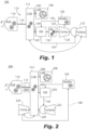
- Fig. 1 a partial view of an exemplary embodiment of a hybrid propulsion system in accordance with the disclosure is shown in Fig. 1 and is designated generally by reference character 100.
- Other embodiments of hybrid propulsion systems in accordance with the disclosure, or aspects thereof, are provided in Figs. 2-15 , as will be described.
- the systems and methods described herein can be used to provide hybrid propulsion, e.g., for improving fuel efficiency in aircraft.
- the hybrid propulsion system 100 includes a heat engine (or motor) 102 configured to drive a heat engine shaft 104.
- An electric motor 106 is configured to drive an electric motor shaft 108.
- a transmission system 110 includes at least one gearbox. The transmission system 110 is configured to receive rotational input power from each of the heat engine shaft 104 and the motor shaft 108 and to convert the rotation input power to output power, as indicated by the circular arrow in Fig. 1 .
- the at least one gearbox includes a combining gearbox 112 connecting to the heat engine shaft 104 and to the motor shaft 108 to combine rotational input power from the heat engine 102 and electric motor 106 for providing rotational output power to an output shaft 114, which can drive a reduction gearbox 116 for turning an aircraft propeller, fan, or any other suitable type of air mover for example.
- a turbine gearbox 118 is included, which is connected between the heat engine shaft 104 and a shaft 120 for driving a turbine 122 and a compressor 124 to drive the turbine 122 and compressor 124 at a different rotational speed from the heat engine 102.
- the heat engine 102 can run at 8000 revolutions per minute (RPM), the heat engines exhaust can be recovered by the turbine 122 to drive the compressor 120 at 35,000 RPM.
- the turbine gearbox 118 can be a two speed transmission or constant velocity transmission (CVT) which can eliminate the need for a variable inlet guide vane (VIGV) controlling the compressor 124.
- VGV variable inlet guide vane
- the turbine 122 and compressor 124 can separately connect to the turbine gear box 118, e.g., using a concentric shaft for the compressor such as the shaft 1246 shown in Fig. 14 , so that the turbine 122 and compressor 124 can rotate at different rotational speeds.
- These types of turbine gearbox can apply to each of the turbine gearboxes described below, even if not specifically repeated.
- the compressor 120 compresses air and supplies the compressed air to the heat engine 102 through the air line 126, which includes heat exchanger 128 for cooling the compressed air. After combustion in the heat engine 102, the combustion products are supplied through a combustion products line 130 to the turbine 122, which extracts power from the compressed combustion products before exhausting them.
- the configurations shown in Figs. 2-15 also include similar air lines 126, heat exchangers 128, and combustion products lines 130, and the details for such are not repeated below for each Figure. Also, unless specified otherwise, the configurations in each of Figs. 2-15 include an output shaft 114 connecting between a combining gearbox (e.g. combining gearbox 112) and reduction gearbox 116, the details of which will not be repeated below for each Figure.
- the electric motor 106 can be powered to boost horse power, e.g., for take-off, in parallel with the heat motor 102, and can be powered down, e.g., for cruising in level flight, where only the heat motor 102 is needed for power. It is also contemplated that the electric motor 106 can be used as a generator to recharge the battery, e.g. source 1138 of Fig. 13 , when power is available from the heat engine 102 or form wind milling the propeller to drive the reduction gear box 116.
- the compressor 124 and turbine 122 improve the thermal efficiency of the heat engine 102. Similar benefits are derived with the configurations described below with respect to Figs. 2-15 .
- FIG. 1 schematically indicates that the turbine 122 can optionally be moved to connect directly to the combining gearbox 112, much as described below with respect to Fig. 13 , which switch in turbine position can also be applied to other arrangements described below wherein the compressor and turbine are shown and described as being on a common shaft.
- a system 200 includes a combining gearbox 212 connecting to the heat engine shaft 204, the motor shaft 208, and a shaft 220 for driving the turbine 222 and compressor 224.
- the combining gearbox 212 combines rotational input power from the heat engine (or motor) 202 and electric motor 206 for providing rotational output power to an output shaft 114 and to drive the turbine 222 and compressor 224. While connected on a common shaft 220, the turbine 222 and compressor 224 can be connected on opposite sides of the combining gearbox 212 as shown in Fig. 2 . It is also contemplated that the turbine 222 and compressor 224 can both be connected on one side of the combining gearbox 212, as shown in Fig. 3 .
- the portion of the combining gearbox 212 that drives the shaft 220 can be a two speed transmission or constant velocity transmission (CVT) which can eliminate the need for a variable inlet guide vane (VIGV) controlling the compressor 224.
- CVT constant velocity transmission
- VIGV variable inlet guide vane
- a system 300 is shown wherein the heat engine shaft 304 and the electric motor shaft 308 are connected for common rotation.
- a reduction gearbox 316 e.g. for ultimately outputting power to a propeller, is connected to a common output shaft 305 of the electric motor 306 and the heat engine 302.
- a turbine gearbox 332 is connected between the heat engine shaft 304 and a shaft 320 for rotation of the turbine 322 and compressor 324 at a different rotational speed from the heat engine 302 and electric motor 306.
- the broken line in Fig. 4 indicates that the position of the heat engine 302 and electric motor 306 can be reversed on the common shaft 305.
- each of the heat engine 302 and electric motor can be connected to the reduction gearbox 316 through a concentric shaft, e.g. as indicated by the broken lines between the electric motor 306 and the reduction gear box 316.
- a concentric shaft e.g. as indicated by the broken lines between the electric motor 306 and the reduction gear box 316.
- the heat engine shaft 404 and electric motor shaft 408 are concentric with a shaft 420 for rotation of the turbine 422 and compressor 424.
- the heat engine shaft 404 and electric motor shaft 408 can be a common shaft 405 as shown in Fig. 5 , or can themselves be concentric with one another as indicated by the broken lines in Fig. 5 .
- a reduction gearbox 416 is connected to each of the heat engine shaft 404 and the electric motor shaft 408, e.g., for driving a propeller with rotational input from the heat engine 402 and electric motor 406.
- the reduction gearbox 416 connects to a shaft 420 for rotation of the turbine 422 and compressor 424.
- a system 500 has a heat engine shaft 504 and the electric motor shaft 508 connected for common rotation.
- a combining gearbox 512 connects to the common output shaft 505 of the electric motor 506 and the heat engine 502 and a shaft 520 for driving a turbine 522 and compressor 524, to combine rotational input power from the heat engine 502 and electric motor 506 for providing rotational output power to an output shaft 114 and to drive the turbine 522 and compressor 524.
- the turbine 522 and compressor 524 are connected on opposite sides of the combining gearbox 512. As shown in Fig. 7 , it is also contemplated that the turbine 522 and compressor 524 can both be on one side of the combining gearbox 512.
- the broken lines in Figs. 6 and 7 schematically indicate that the positions of the heat motor 502 and electric motor 506 can be switched.
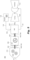
- a system 600 includes a combining gearbox 612 connecting to the heat engine shaft 604 and to the electric motor shaft 608 to combine rotational input power from the heat engine 602 and electric motor 606 for providing rotational output power to an output shaft 114.
- a turbine driver motor/generator 634 is connected to a shaft 620 for driving a turbine 622 and a compressor 624 to drive the turbine 622 and compressor 624 at a different rotational speed ratio from the heat engine 602 and electric motor 606.
- the compressor 624 can therefore be a variable speed compressor.
- An electrical system 636 includes a storage 638, e.g., a battery, battery bank, capacitor, capacitor bank, super capacitor or super capacitor bank, flywheel or flywheel bank, or the like, is connected to a first inverter/rectifier component 640 for supplying power from the storage 638 to drive the electric motor 606 or in an energy recovery mode, to store into the storage 638 energy generated by driving the electric motor 606 in a generator mode.
- the electrical system 636 includes a second invert/rectifier component 642 for supplying power to drive the turbine driver motor 634, or to recover energy into the storage 638 from the turbine drive motor 634 if run in a generator mode.
- the broken line in Fig. 8 schematically indicates that the position of the motor 634 and compressor can be switched on the shaft 620.
- Figs. 9 , 10 , 11 , and 12 each show similar electrical systems 636 and the description thereof is not repeated below.
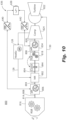
- a system 700 has the heat engine shaft 704 and the electric motor shaft 108 are connected for common rotation.
- a reduction gearbox 716 connected to a common output shaft 714 of the electric motor 706 and the heat engine 702.
- a turbine driver motor 734 is connected to a shaft 720 for driving a turbine 722 and a compressor 724 at a different rotational speed from the heat engine 702 and electric motor 706.
- the broken arrows in Fig. 9 schematically indicate that the position of the heat engine 702 and the electric motor 706 can be switched on the common shaft 714, and that the positions of the motor 734 and compressor 724 can be switched on the shaft 720.
- the heat engine shaft 804 and the electric motor shaft 808 are connected for common rotation.
- a reduction gearbox 816 is connected to a common output shaft 814 of the electric motor 806 and the heat engine 802.
- a turbine gearbox 818 is connected through a clutch 844 between the heat engine shaft 804 and a shaft 820 for driving a turbine 822 and a compressor 824 at a different rotational speed ratio from the heat engine 802 and electric motor 802 when the clutch 844 is engaged.
- the shaft 820 for driving the turbine 822 and compressor 824 is connected to a turbine driver motor 834 to drive the turbine 822 and compressor 824 independently from the heat engine 802 and electric motor 806 when the clutch 844 is disengaged.
- the clutch 844 can prevent electrical losses at steady state because the clutch engages when system 800 steady state operation, e.g., cruising in level flight, so the shaft 820 is connected to the heat engine 802 to avoid electrical conversion losses. In transients, the clutch 844 can open or disconnect to allow the motor 834 to drive the shaft 820 at a different speed ratio from the heat engine 802 as described above.
- a system 900 includes a heat engine shaft 904 and electric motor shaft 908 that are concentric with the shaft 20 for rotation of the turbine 922 and compressor 924 similar to the arrangement in Fig. 5 .
- a reduction gearbox 916 is connected to each of the heat engine shaft 904 and the electric motor shaft 908, e.g., as a common shaft 905 or concentric with one another as described above with respect to Fig. 5 .
- a clutch 944 in the shaft 920 connects between the heat engine 902 and a turbine driver motor 934 for rotating the turbine 922 and compressor 924 with the reduction gear box 916 when the clutch 944 is engaged, and to drive the turbine 922 and compressor 924 independently from the heat engine 902 and electric motor 906 when the clutch 944 is disengaged.
- a system 1000 includes a heat engine shaft 1004 and electric motor shaft 1008 are connected for common rotation.
- a reduction gearbox 1016 is connected to a common output shaft 1014 of the electric motor 1006 and the heat engine 1002.
- the upper broken lines in Fig. 12 schematically indicate that the positions of the heat engine 1002 and the motor 1006 can be switched on the shaft 1014.
- a clutch 1044 connects between the reduction gearbox 1016 and a turbine driver motor 1034 connected to a shaft 1020 for driving a turbine 1022 and a compressor 1024 with rotational power from the heat engine 1002 and electric motor 1002 (through the reduction gearbox 1016) when the clutch 1044 is engaged, and to drive the turbine 1022 and compressor 1024 independently from the heat engine 1002 and electric motor 1006 when the clutch 1044 is disengaged.
- the lower broken line in Fig. 12 schematically indicates that the positions of the motor 1034 and the compressor 1024 can be switched on the shaft 1020.
- a system 1100 is shown wherein the heat engine shaft 1104 and the electric motor shaft 1108 are connected for common rotation.
- a combining gearbox 1112 connects to a common output shaft 1105 of the electric motor 1106 and the heat engine 1102, and to a shaft 1114 of a turbine 1122 to combine rotational input power from the heat engine 1102, electric motor 1106, and turbine 1122 for providing rotational output power to an output shaft 1114.
- a reduction gearbox 1116 is connected to the output shaft 1114, wherein a compressor 1124 is connected to be driven on the output shaft 1114.
- An electrical system 1136 includes a storage 1138 connected through an inverter/rectifier component 1140 to supply power to the motor 1106, or to recover power from the motor 1106 in a generator mode to store in the storage 1138.
- the other arrangements described above that do not specifically show an electrical system can include a system similar to electrical system 1136, and Fig. 14 includes a similar system 1136 even though the details are not repeated.
- the compressor 1124 can also be connected to the reduction gearbox 1116 on its own shaft concentric with the shaft 1114, much as described below with respect to Fig. 14 .
- the turbine 1122 can be mechanically decoupled from the CGB to drive a generator 1134, which can be connected through an inverter/rectifier component 1142 to charge the storage 1138, which can similarly be applied to other arrangements disclosed herein with the turbine decoupled from the compressor.
- the compressor and a gear box 1118 can be connected to the heat engine 1102 in lieu of connecting the compressor 1124 on the output shaft 1114.
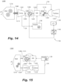
- a system 1200 is shown wherein the heat engine shaft 1204 and the electric motor shaft 1208 are connected for common rotation.
- a reduction gearbox 1216 connected to a common output shaft 1214 of the electric motor 1206 and the heat engine 1202.
- a turbine gearbox 1218 is connected between the heat engine shaft 1204 and a shaft 1220 of a turbine 1222 so the turbine can rotate at a different rotational speed from the heat engine 1202 and electric motor 1206.
- a compressor 1224 is connected to the reduction gearbox 1216 through a compressor shaft 1246 concentric with the common output shaft 1214 so the compressor can be driven at a different speed from the common output shaft 1214.
- a system 1300 includes a heat engine shaft 1304 and the electric motor shaft 1308 that are connected for common rotation.
- a super position gearbox 1316 connects to a common output shaft 1314 of the electric motor 1306 and the heat engine 1302, and to a shaft 1320 for driving a turbine 1322 and compressor 1324 to combine rotational input power from the heat engine 1302 and electric motor 1306 for providing rotational output power to an output shaft 1314 and to drive the turbine 1322 and compressor 1324.
- the super position gearbox 1316 is configured so the speed ratio between the common output shaft 1314 and the shaft 1320 for driving the turbine 1322 and compressor 1324 can vary, e.g., to adjust the speed of the compressor 1324 for altitude or for ground idle.
- the turbine 1322 can optionally be decoupled from the compressor 1324 to drive a generator as described above with reference to Fig. 13 .
- the arrangement in Fig. 3 can be modified so the turbine 222 is decoupled from the compressor 224 to drive a generator.
- the heat engine e.g., heat engine 202 in Fig. 2
- each of the shafts 104 and 108 can be included, e.g., in each of the shafts 104 and 108 as indicated in Fig. 1 by the broken lines crossing the shafts 104 and 108, for disconnecting the heat engine 102 or electric motor 106 as needed.
- This can also be applied to other embodiments disclosed above besides the arrangement in Fig. 1 .
- modules are represented schematically herein vertically on top of each other, those skilled in the art having the benefit of this discourse will readily appreciate that they can be located side by side, one above the other or in any geometrical arrangement and in any order in physical implementations.
- modules represented on one side (right or left) of the respective gearbox herein can also potentially be installed on the other side or even trapped between a respecting reduction gearbox and combining gear box.
- Module disclosed herein can be installed directly on the respective combining gear box or reduction gear box with a proper speed ratio.
- modules are represented herein with an axial orientation
- bevel gears or other mechanical or electrical devices
- accessories not explicitly represented herein can be included and can potentially be connected mechanically to any module or driven electrically similar to the modules and components disclosed herein.
- combining gearboxes and reduction gearboxes disclosed above can be combined into a single respective gearbox.
Landscapes
- Engineering & Computer Science (AREA)
- Mechanical Engineering (AREA)
- Aviation & Aerospace Engineering (AREA)
- General Engineering & Computer Science (AREA)
- Power Engineering (AREA)
- Chemical & Material Sciences (AREA)
- Combustion & Propulsion (AREA)
- Supercharger (AREA)
- Engine Equipment That Uses Special Cycles (AREA)
- Hybrid Electric Vehicles (AREA)
Abstract
Description
- The present disclosure relates to aircraft engines, and more particularly to hybrid aircraft engines.
- Aircraft engines vary in efficiency and function over a plurality of parameters, such as thrust requirements, air temperature, air speed, altitude, and the like. Aircraft require the most thrust at take-off, wherein the demand for engine power is the heaviest. However, during the remainder of the mission, the aircraft engines often do not require as much thrust as during take-off. The size and weight of the engines allows them to produce the power needed for take-off, however after take-off the engines are in effect over-sized for the relatively low power required to produce thrust for cruising in level flight.
- The conventional techniques have been considered satisfactory for their intended purpose. However, there is an ever present need for improved aircraft engines. This disclosure provides a solution for this need.
- A hybrid propulsion system includes a heat engine configured to drive a heat engine shaft. An electric motor is configured to drive an electric motor shaft. A transmission system includes at least one gearbox. The transmission system is configured to receive rotational input power from each of the heat engine shaft and the electric motor shaft and to convert the rotation input power to output power.
- The at least one gearbox can include a combining gearbox connecting to the heat engine shaft and to the electric motor shaft to combine rotational input power from the heat engine and electric motor for providing rotational output power to an output shaft. A turbine gearbox can be included, wherein the turbine gearbox is connected between the heat engine shaft and a shaft for driving a turbine and a compressor to drive the turbine and compressor at a different rotational speed from the heat engine.
- The at least one gearbox can include a combining gearbox connecting to the heat engine shaft, the electric motor shaft, and a shaft for driving a turbine and compressor, to combine rotational input power from the heat engine and electric motor for providing rotational output power to an output shaft and to drive the turbine and compressor. The turbine and compressor can both be on one side of the combining gearbox. It is also contemplated that the turbine and compressor can be connected on opposite sides of the combining gearbox.
- The heat engine shaft and the electric motor shaft can be connected for common rotation.
- The at least one gearbox can include a reduction gearbox connected to a common output shaft of the electric motor and the heat engine, and a turbine gearbox can be connected between the heat engine shaft and a shaft for driving a turbine and a compressor to drive the turbine and compressor at a different rotational speed from the heat engine and electric motor.
- The heat engine shaft and electric motor shaft can be concentric with a shaft for rotation of the turbine and compressor, wherein the at least one gearbox includes a reduction gearbox connected to each of the heat engine shaft and the electric motor shaft and to the shaft for rotation of the turbine and compressor.
- In another aspect, the heat engine shaft and the electric motor shaft can be connected for common rotation. The at least one gearbox can include a combining gearbox connecting to a common output shaft of the electric motor and the heat engine and a shaft for driving a turbine and compressor, to combine rotational input power from the heat engine and electric motor for providing rotational output power to an output shaft and to drive the turbine and compressor. The turbine and compressor can both be on one side of the combining gearbox. It is also contemplated that the turbine and compressor can be connected on opposite sides of the combining gearbox.
- The at least one gearbox can include a combining gearbox connecting to the heat engine shaft and to the electric motor shaft to combine rotational input power from the heat engine and electric motor for providing rotational output power to an output shaft. A turbine driver motor can be connected to a shaft for driving a turbine and a compressor to drive the turbine and compressor at a different rotational speed ratio from the heat engine and electric motor.
- In another aspect, the heat engine shaft and the electric motor shaft can be connected for common rotation. The at least one gearbox can include a reduction gearbox connected to a common output shaft of the electric motor and the heat engine. A turbine driver motor can be connected to a shaft for driving a turbine and a compressor to drive the turbine and compressor at a different rotational speed ratio from the heat engine and electric motor.
- In another aspect, the heat engine shaft and the electric motor shaft can be connected for common rotation. The at least one gearbox can include a reduction gearbox connected to a common output shaft of the electric motor and the heat engine. A turbine gearbox can be connected through a clutch between the heat engine shaft and a shaft for driving a turbine and a compressor to drive the turbine and compressor at a different rotational speed from the heat engine and electric motor when the clutch is engaged. The shaft for driving the turbine and compressor can be connected to a turbine driver motor to drive the turbine and compressor independently from the heat engine and electric motor when the clutch is disengaged.
- In another aspect, the heat engine shaft and electric motor shaft can be concentric with a shaft for rotation of a turbine and compressor. The at least one gearbox can include a reduction gearbox connected to each of the heat engine shaft and the electric motor shaft. A clutch in the shaft for rotation of the turbine and compressor can connect between the reduction gearbox a turbine driver motor connected to the shaft for rotation of the turbine and a compressor to drive the turbine and compressor with the reduction gearbox when the clutch is engaged, and to drive the turbine and compressor independently from the heat engine and electric motor when the clutch is disengaged.
- In another aspect, the heat engine shaft and the electric motor shaft can be connected for common rotation. The at least one gearbox can include a reduction gearbox connected to a common output shaft of the electric motor and the heat engine. A clutch can connect between the reduction gearbox and a turbine driver motor connected to a shaft for driving a turbine and a compressor to drive the turbine and compressor with rotational power from the heat engine and electric motor when the clutch is engaged, and to drive the turbine and compressor independently from the heat engine and electric motor when the clutch is disengaged.
- In another aspect, the heat engine shaft and the electric motor shaft can be connected for common rotation. The at least one gearbox can include a combining gearbox connecting to a common output shaft of the electric motor and the heat engine, and a shaft of a turbine to combine rotational input power from the heat engine, electric motor, and turbine for providing rotational output power to an output shaft. A reduction gearbox can be connected to the output shaft, wherein a compressor is connected to be driven on the output shaft.
- In another aspect, the heat engine shaft and the electric motor shaft can be connected for common rotation. The at least one gearbox can include a reduction gearbox connected to a common output shaft of the electric motor and the heat engine. A turbine gearbox can be connected between the heat engine shaft and a shaft of a turbine so the turbine can rotate at a different rotational speed from the heat engine and electric motor. A compressor can be connected to the reduction gearbox through a compressor shaft concentric with the common output shaft so the compressor can be driven at a different rotational speed from the common output shaft.
- In another aspect, the heat engine shaft and the electric motor shaft can be connected for common rotation. The at least one gearbox can include a super position gearbox connecting to a common output shaft of the electric motor and the heat engine, and a shaft for driving a turbine and compressor to combine rotational input power from the heat engine and electric motor for providing rotational output power to an output shaft and to drive the turbine and compressor.
The super position gearbox can be configured so speed ratio between the common output shaft and the shaft for driving the turbine and compressor can vary. - A turbine can be connected to the heat engine to be driven by exhaust form the heat engine, and a generator can be connected to be driven by the turbine.
- These and other features of the systems and methods of the subject disclosure will become more readily apparent to those skilled in the art from the following detailed description of the preferred embodiments taken in conjunction with the drawings.
- So that those skilled in the art to which the subject disclosure appertains will readily understand how to make and use the devices and methods of the subject disclosure without undue experimentation, preferred embodiments thereof will be described in detail herein below with reference to certain figures, wherein:
-
Fig. 1 is a schematic view of an exemplary embodiment of a hybrid propulsion system constructed in accordance with the present disclosure, showing a first gearbox arrangement; -
Fig. 2 is a schematic view of an exemplary embodiment of a hybrid propulsion system constructed in accordance with the present disclosure, showing a second gearbox arrangement; -
Fig. 3 is a schematic view of an exemplary embodiment of a hybrid propulsion system constructed in accordance with the present disclosure, showing a third gearbox arrangement; -
Fig. 4 is a schematic view of an exemplary embodiment of a hybrid propulsion system constructed in accordance with the present disclosure, showing a fourth gearbox arrangement; -
Fig. 5 is a schematic view of an exemplary embodiment of a hybrid propulsion system constructed in accordance with the present disclosure, showing a fifth gearbox arrangement; -
Fig. 6 is a schematic view of an exemplary embodiment of a hybrid propulsion system constructed in accordance with the present disclosure, showing a sixth gearbox arrangement; -
Fig. 7 is a schematic view of an exemplary embodiment of a hybrid propulsion system constructed in accordance with the present disclosure, showing a seventh gearbox arrangement; -
Fig. 8 is a schematic view of an exemplary embodiment of a hybrid propulsion system constructed in accordance with the present disclosure, showing an eighth gearbox arrangement; -
Fig. 9 is a schematic view of an exemplary embodiment of a hybrid propulsion system constructed in accordance with the present disclosure, showing a ninth gearbox arrangement; -
Fig. 10 is a schematic view of an exemplary embodiment of a hybrid propulsion system constructed in accordance with the present disclosure, showing a tenth gearbox arrangement; -
Fig. 11 is a schematic view of an exemplary embodiment of a hybrid propulsion system constructed in accordance with the present disclosure, showing an eleventh gearbox arrangement; -
Fig. 12 is a schematic view of an exemplary embodiment of a hybrid propulsion system constructed in accordance with the present disclosure, showing a twelfth gearbox arrangement; -
Fig. 13 is a schematic view of an exemplary embodiment of a hybrid propulsion system constructed in accordance with the present disclosure, showing a thirteenth gearbox arrangement; -
Fig. 14 is a schematic view of an exemplary embodiment of a hybrid propulsion system constructed in accordance with the present disclosure, showing a fourteenth gearbox arrangement; and -
Fig. 15 is a schematic view of an exemplary embodiment of a hybrid propulsion system constructed in accordance with the present disclosure, showing a fifteenth gearbox arrangement. - Reference will now be made to the drawings wherein like reference numerals identify similar structural features or aspects of the subject disclosure. For purposes of explanation and illustration, and not limitation, a partial view of an exemplary embodiment of a hybrid propulsion system in accordance with the disclosure is shown in
Fig. 1 and is designated generally byreference character 100. Other embodiments of hybrid propulsion systems in accordance with the disclosure, or aspects thereof, are provided inFigs. 2-15 , as will be described. The systems and methods described herein can be used to provide hybrid propulsion, e.g., for improving fuel efficiency in aircraft. - The
hybrid propulsion system 100 includes a heat engine (or motor) 102 configured to drive aheat engine shaft 104. Anelectric motor 106 is configured to drive anelectric motor shaft 108. Atransmission system 110 includes at least one gearbox. Thetransmission system 110 is configured to receive rotational input power from each of theheat engine shaft 104 and themotor shaft 108 and to convert the rotation input power to output power, as indicated by the circular arrow inFig. 1 . - The at least one gearbox includes a combining
gearbox 112 connecting to theheat engine shaft 104 and to themotor shaft 108 to combine rotational input power from theheat engine 102 andelectric motor 106 for providing rotational output power to anoutput shaft 114, which can drive areduction gearbox 116 for turning an aircraft propeller, fan, or any other suitable type of air mover for example. Aturbine gearbox 118 is included, which is connected between theheat engine shaft 104 and ashaft 120 for driving aturbine 122 and acompressor 124 to drive theturbine 122 andcompressor 124 at a different rotational speed from theheat engine 102. For example, through theturbine gearbox 118, theheat engine 102 can run at 8000 revolutions per minute (RPM), the heat engines exhaust can be recovered by theturbine 122 to drive thecompressor 120 at 35,000 RPM. Theturbine gearbox 118 can be a two speed transmission or constant velocity transmission (CVT) which can eliminate the need for a variable inlet guide vane (VIGV) controlling thecompressor 124. It is also contemplated that theturbine 122 andcompressor 124 can separately connect to theturbine gear box 118, e.g., using a concentric shaft for the compressor such as theshaft 1246 shown inFig. 14 , so that theturbine 122 andcompressor 124 can rotate at different rotational speeds. These types of turbine gearbox can apply to each of the turbine gearboxes described below, even if not specifically repeated. - Those skilled in the art will readily appreciate that while described herein in the context of driving the
turbine 122 andcompressor 124, that theturbine 122 can actually add power to theshaft 120 and therefore cooperates with theheat engine 102 to drive the combininggearbox 112, however, in configurations herein where theturbine 122 andcompressor 124 spin at a common speed thecompressor 124 andturbine 122 are collectively referred to herein as driven. - The
compressor 120 compresses air and supplies the compressed air to theheat engine 102 through theair line 126, which includesheat exchanger 128 for cooling the compressed air. After combustion in theheat engine 102, the combustion products are supplied through a combustion products line 130 to theturbine 122, which extracts power from the compressed combustion products before exhausting them. The configurations shown inFigs. 2-15 also includesimilar air lines 126,heat exchangers 128, andcombustion products lines 130, and the details for such are not repeated below for each Figure. Also, unless specified otherwise, the configurations in each ofFigs. 2-15 include anoutput shaft 114 connecting between a combining gearbox (e.g. combining gearbox 112) andreduction gearbox 116, the details of which will not be repeated below for each Figure. Theelectric motor 106 can be powered to boost horse power, e.g., for take-off, in parallel with theheat motor 102, and can be powered down, e.g., for cruising in level flight, where only theheat motor 102 is needed for power. It is also contemplated that theelectric motor 106 can be used as a generator to recharge the battery,e.g. source 1138 ofFig. 13 , when power is available from theheat engine 102 or form wind milling the propeller to drive thereduction gear box 116. Thecompressor 124 andturbine 122 improve the thermal efficiency of theheat engine 102. Similar benefits are derived with the configurations described below with respect toFigs. 2-15 . The dashed line inFig. 1 schematically indicates that theturbine 122 can optionally be moved to connect directly to the combininggearbox 112, much as described below with respect toFig. 13 , which switch in turbine position can also be applied to other arrangements described below wherein the compressor and turbine are shown and described as being on a common shaft. - With reference now to
Fig. 2 , asystem 200 includes a combininggearbox 212 connecting to theheat engine shaft 204, themotor shaft 208, and ashaft 220 for driving theturbine 222 andcompressor 224. The combininggearbox 212 combines rotational input power from the heat engine (or motor) 202 andelectric motor 206 for providing rotational output power to anoutput shaft 114 and to drive theturbine 222 andcompressor 224. While connected on acommon shaft 220, theturbine 222 andcompressor 224 can be connected on opposite sides of the combininggearbox 212 as shown inFig. 2 . It is also contemplated that theturbine 222 andcompressor 224 can both be connected on one side of the combininggearbox 212, as shown inFig. 3 . The portion of the combininggearbox 212 that drives theshaft 220 can be a two speed transmission or constant velocity transmission (CVT) which can eliminate the need for a variable inlet guide vane (VIGV) controlling thecompressor 224. This applies to arrangements described below wherein the turbine and compressor connect directly to a combined gearbox, even if not specifically repeated. - With reference now to
Fig. 4 , asystem 300 is shown wherein the heat engine shaft 304 and the electric motor shaft 308 are connected for common rotation. Areduction gearbox 316, e.g. for ultimately outputting power to a propeller, is connected to a common output shaft 305 of theelectric motor 306 and theheat engine 302. A turbine gearbox 332 is connected between the heat engine shaft 304 and a shaft 320 for rotation of theturbine 322 andcompressor 324 at a different rotational speed from theheat engine 302 andelectric motor 306. The broken line inFig. 4 indicates that the position of theheat engine 302 andelectric motor 306 can be reversed on the common shaft 305. If there is a requirement to guarantee power from one of theheat engine 302 orelectric motor 306 in the event of stoppage of the other, each of theheat engine 302 and electric motor can be connected to thereduction gearbox 316 through a concentric shaft, e.g. as indicated by the broken lines between theelectric motor 306 and thereduction gear box 316. The same applies to other configurations herein where the heat engine and electric motor are shown and described as having a common output shaft. - With reference now to
Fig. 5 , in thesystem 400, the heat engine shaft 404 and electric motor shaft 408 are concentric with ashaft 420 for rotation of theturbine 422 andcompressor 424. The heat engine shaft 404 and electric motor shaft 408 can be a common shaft 405 as shown inFig. 5 , or can themselves be concentric with one another as indicated by the broken lines inFig. 5 . Areduction gearbox 416 is connected to each of the heat engine shaft 404 and the electric motor shaft 408, e.g., for driving a propeller with rotational input from theheat engine 402 andelectric motor 406. Thereduction gearbox 416 connects to ashaft 420 for rotation of theturbine 422 andcompressor 424. - With reference now to
Fig. 6 , asystem 500 has a heat engine shaft 504 and the electric motor shaft 508 connected for common rotation. A combininggearbox 512 connects to the common output shaft 505 of theelectric motor 506 and the heat engine 502 and ashaft 520 for driving aturbine 522 andcompressor 524, to combine rotational input power from the heat engine 502 andelectric motor 506 for providing rotational output power to anoutput shaft 114 and to drive theturbine 522 andcompressor 524. Theturbine 522 andcompressor 524 are connected on opposite sides of the combininggearbox 512. As shown inFig. 7 , it is also contemplated that theturbine 522 andcompressor 524 can both be on one side of the combininggearbox 512. The broken lines inFigs. 6 and 7 schematically indicate that the positions of the heat motor 502 andelectric motor 506 can be switched. - Referring now to
Fig. 8 , asystem 600 includes a combininggearbox 612 connecting to the heat engine shaft 604 and to theelectric motor shaft 608 to combine rotational input power from theheat engine 602 andelectric motor 606 for providing rotational output power to anoutput shaft 114. A turbine driver motor/generator 634 is connected to ashaft 620 for driving aturbine 622 and acompressor 624 to drive theturbine 622 andcompressor 624 at a different rotational speed ratio from theheat engine 602 andelectric motor 606. Thecompressor 624 can therefore be a variable speed compressor. Anelectrical system 636 includes astorage 638, e.g., a battery, battery bank, capacitor, capacitor bank, super capacitor or super capacitor bank, flywheel or flywheel bank, or the like, is connected to a first inverter/rectifier component 640 for supplying power from thestorage 638 to drive theelectric motor 606 or in an energy recovery mode, to store into thestorage 638 energy generated by driving theelectric motor 606 in a generator mode. Theelectrical system 636 includes a second invert/rectifier component 642 for supplying power to drive theturbine driver motor 634, or to recover energy into thestorage 638 from theturbine drive motor 634 if run in a generator mode. The broken line inFig. 8 schematically indicates that the position of themotor 634 and compressor can be switched on theshaft 620.Figs. 9 ,10 ,11 , and12 each show similarelectrical systems 636 and the description thereof is not repeated below. - With reference now to
Fig. 9 , asystem 700 has theheat engine shaft 704 and theelectric motor shaft 108 are connected for common rotation. Areduction gearbox 716 connected to a common output shaft 714 of theelectric motor 706 and theheat engine 702. Aturbine driver motor 734 is connected to ashaft 720 for driving aturbine 722 and acompressor 724 at a different rotational speed from theheat engine 702 andelectric motor 706. The broken arrows inFig. 9 schematically indicate that the position of theheat engine 702 and theelectric motor 706 can be switched on the common shaft 714, and that the positions of themotor 734 andcompressor 724 can be switched on theshaft 720. - Referring now to
Fig. 10 , in thesystem 800 theheat engine shaft 804 and theelectric motor shaft 808 are connected for common rotation. Areduction gearbox 816 is connected to a common output shaft 814 of theelectric motor 806 and theheat engine 802. Aturbine gearbox 818 is connected through a clutch 844 between theheat engine shaft 804 and ashaft 820 for driving aturbine 822 and acompressor 824 at a different rotational speed ratio from theheat engine 802 andelectric motor 802 when the clutch 844 is engaged. Theshaft 820 for driving theturbine 822 andcompressor 824 is connected to aturbine driver motor 834 to drive theturbine 822 andcompressor 824 independently from theheat engine 802 andelectric motor 806 when the clutch 844 is disengaged. The broken lines inFig. 10 schematically indicate that the positions of the clutch 844 and theturbine gearbox 818 can be switched. The clutch 844 can prevent electrical losses at steady state because the clutch engages whensystem 800 steady state operation, e.g., cruising in level flight, so theshaft 820 is connected to theheat engine 802 to avoid electrical conversion losses. In transients, the clutch 844 can open or disconnect to allow themotor 834 to drive theshaft 820 at a different speed ratio from theheat engine 802 as described above. - With respect to
Fig. 11 , asystem 900 includes a heat engine shaft 904 and electric motor shaft 908 that are concentric with the shaft 20 for rotation of theturbine 922 andcompressor 924 similar to the arrangement inFig. 5 . Areduction gearbox 916 is connected to each of the heat engine shaft 904 and the electric motor shaft 908, e.g., as a common shaft 905 or concentric with one another as described above with respect toFig. 5 . A clutch 944 in theshaft 920 connects between theheat engine 902 and aturbine driver motor 934 for rotating theturbine 922 andcompressor 924 with thereduction gear box 916 when the clutch 944 is engaged, and to drive theturbine 922 andcompressor 924 independently from theheat engine 902 andelectric motor 906 when the clutch 944 is disengaged. - With reference now to
Fig. 12 , asystem 1000 includes aheat engine shaft 1004 andelectric motor shaft 1008 are connected for common rotation. Areduction gearbox 1016 is connected to acommon output shaft 1014 of theelectric motor 1006 and theheat engine 1002. The upper broken lines inFig. 12 schematically indicate that the positions of theheat engine 1002 and themotor 1006 can be switched on theshaft 1014. A clutch 1044 connects between thereduction gearbox 1016 and aturbine driver motor 1034 connected to ashaft 1020 for driving aturbine 1022 and acompressor 1024 with rotational power from theheat engine 1002 and electric motor 1002 (through the reduction gearbox 1016) when the clutch 1044 is engaged, and to drive theturbine 1022 andcompressor 1024 independently from theheat engine 1002 andelectric motor 1006 when the clutch 1044 is disengaged. The lower broken line inFig. 12 schematically indicates that the positions of themotor 1034 and thecompressor 1024 can be switched on theshaft 1020. - Referring now to
Fig. 13 , asystem 1100 is shown wherein theheat engine shaft 1104 and the electric motor shaft 1108 are connected for common rotation. A combininggearbox 1112 connects to a common output shaft 1105 of theelectric motor 1106 and theheat engine 1102, and to ashaft 1114 of aturbine 1122 to combine rotational input power from theheat engine 1102,electric motor 1106, andturbine 1122 for providing rotational output power to anoutput shaft 1114. Areduction gearbox 1116 is connected to theoutput shaft 1114, wherein acompressor 1124 is connected to be driven on theoutput shaft 1114. Anelectrical system 1136 includes astorage 1138 connected through an inverter/rectifier component 1140 to supply power to themotor 1106, or to recover power from themotor 1106 in a generator mode to store in thestorage 1138. The other arrangements described above that do not specifically show an electrical system can include a system similar toelectrical system 1136, andFig. 14 includes asimilar system 1136 even though the details are not repeated. Thecompressor 1124 can also be connected to thereduction gearbox 1116 on its own shaft concentric with theshaft 1114, much as described below with respect toFig. 14 . The broken lines inFig. 13 indicate that optionally theturbine 1122 can be mechanically decoupled from the CGB to drive agenerator 1134, which can be connected through an inverter/rectifier component 1142 to charge thestorage 1138, which can similarly be applied to other arrangements disclosed herein with the turbine decoupled from the compressor. As indicated by broken lines inFig. 13 , the compressor and agear box 1118 can be connected to theheat engine 1102 in lieu of connecting thecompressor 1124 on theoutput shaft 1114. - With reference now to
Fig. 14 , asystem 1200 is shown wherein theheat engine shaft 1204 and theelectric motor shaft 1208 are connected for common rotation. Areduction gearbox 1216 connected to acommon output shaft 1214 of theelectric motor 1206 and theheat engine 1202. Aturbine gearbox 1218 is connected between theheat engine shaft 1204 and ashaft 1220 of aturbine 1222 so the turbine can rotate at a different rotational speed from theheat engine 1202 andelectric motor 1206. Acompressor 1224 is connected to thereduction gearbox 1216 through acompressor shaft 1246 concentric with thecommon output shaft 1214 so the compressor can be driven at a different speed from thecommon output shaft 1214. - Referring now to
Fig. 15 , asystem 1300 includes aheat engine shaft 1304 and the electric motor shaft 1308 that are connected for common rotation. Asuper position gearbox 1316 connects to a common output shaft 1314 of theelectric motor 1306 and theheat engine 1302, and to ashaft 1320 for driving aturbine 1322 andcompressor 1324 to combine rotational input power from theheat engine 1302 andelectric motor 1306 for providing rotational output power to an output shaft 1314 and to drive theturbine 1322 andcompressor 1324. Thesuper position gearbox 1316 is configured so the speed ratio between the common output shaft 1314 and theshaft 1320 for driving theturbine 1322 andcompressor 1324 can vary, e.g., to adjust the speed of thecompressor 1324 for altitude or for ground idle. - The
turbine 1322 can optionally be decoupled from thecompressor 1324 to drive a generator as described above with reference toFig. 13 . Similarly, the arrangement inFig. 3 can be modified so theturbine 222 is decoupled from thecompressor 224 to drive a generator. The heat engine, e.g.,heat engine 202 inFig. 2 , can be split and connected on opposite sides of the respective gear box, e.g., the combinedgearbox 212 inFig. 2 , as indicated inFig. 2 with thebroken line box 202. This split can be applied to other arrangements above besides the one inFig. 2 . Disconnect clutches or mechanism, e.g., clutch 844 inFig. 10 , can be included, e.g., in each of theshafts Fig. 1 by the broken lines crossing theshafts heat engine 102 orelectric motor 106 as needed. This can also be applied to other embodiments disclosed above besides the arrangement inFig. 1 . - Even if modules are represented schematically herein vertically on top of each other, those skilled in the art having the benefit of this discourse will readily appreciate that they can be located side by side, one above the other or in any geometrical arrangement and in any order in physical implementations. Similarly, those skilled in the art having had the benefit of this disclosure will readily appreciate that modules represented on one side (right or left) of the respective gearbox herein can also potentially be installed on the other side or even trapped between a respecting reduction gearbox and combining gear box. Module disclosed herein can be installed directly on the respective combining gear box or reduction gear box with a proper speed ratio. Although modules are represented herein with an axial orientation, those skilled in the art having the benefit of this disclosure will readily appreciate that the use of bevel gears (or other mechanical or electrical devices) allows the installation of modules in any suitable orientation. Those skilled in the art having the benefit of this disclosure will readily appreciate that accessories not explicitly represented herein can be included and can potentially be connected mechanically to any module or driven electrically similar to the modules and components disclosed herein. Those skilled in the art having had the benefit of this disclosure will readily appreciate that combining gearboxes and reduction gearboxes disclosed above can be combined into a single respective gearbox. Finally, those skilled in the art having had the benefit of this disclosure considering the number of parts, will readily appreciate that each architecture disclosed herein can be recombined with other architectures disclosed herein to results in dozens of additional configurations, several examples of which are described above, and all of which are within the scope of this disclosure.
- The methods and systems of the present disclosure, as described above and shown in the drawings, provide for propulsion systems with superior properties including use of hybrid heat engine and electric motor power. While the apparatus and methods of the subject disclosure have been shown and described with reference to preferred embodiments, those skilled in the art will readily appreciate that changes and/or modifications may be made thereto without departing from the scope of the subject disclosure.
- The following numbered clauses define aspects and embodiments of the invention that are disclosed, but not presently claimed:
- 1. A hybrid propulsion system comprising:
- a heat engine configured to drive a heat engine shaft;
- an electric motor configured to drive an electric motor shaft; and
- a transmission system including at least one gearbox, wherein the transmission system is configured to receive rotational input power from each of the heat engine shaft and the electric motor shaft and to convert the rotation input power to output power.
- 2. The system as recited in clause 1, wherein the at least one gearbox includes:
- a combining gearbox connecting to the heat engine shaft and to the electric motor shaft to combine rotational input power from the heat engine and electric motor for providing rotational output power to an output shaft; and
- a turbine gearbox, wherein the turbine gearbox is connected between the heat engine shaft and a shaft for driving a turbine and a compressor to drive the turbine and compressor at a different rotational speed from the heat engine.
- 3. The system as recited in clause 1, wherein the at least one gearbox includes:
- a combining gearbox connecting to:
- the heat engine shaft;
- the electric motor shaft; and
- a shaft for driving a turbine and compressor,
- to combine rotational input power from the heat engine and electric motor for providing rotational output power to an output shaft and to drive the turbine and compressor.
- a combining gearbox connecting to:
- 4. The system as recited in clause 3, wherein one and only one of:
- the turbine and compressor are both on one side of the combining gearbox; or
- the turbine and compressor are connected on opposite sides of the combining gearbox.
- 5. The system as recited in clause 1, wherein the heat engine shaft and the electric motor shaft are connected for common rotation and wherein the at least one gearbox includes:
- a reduction gearbox connected to a common output shaft of the electric motor and the heat engine; and
- a turbine gearbox connected between the heat engine shaft and a shaft for driving a turbine and a compressor to drive the turbine and compressor at a different rotational speed from the heat engine and electric motor.
- 6. The system as recited in clause 1, wherein the heat engine shaft and electric motor shaft are concentric with a shaft for rotation of the turbine and compressor, wherein the at least one gearbox includes a reduction gearbox connected to each of the heat engine shaft and the electric motor shaft and to the shaft for rotation of the a turbine and compressor.
- 7. The system as recited in clause 1, wherein the heat engine shaft and the electric motor shaft are connected for common rotation, and wherein the at least one gearbox includes:
- a combining gearbox connecting to:
- a common output shaft of the electric motor and the heat engine; and
- a shaft for driving a turbine and compressor,
- to combine rotational input power from the heat engine and electric motor for providing rotational output power to an output shaft and to drive the turbine and compressor.
- a combining gearbox connecting to:
- 8. The system as recited in clause 7, wherein one and only one of:
- the turbine and compressor are both on one side of the combining gearbox; or
- the turbine and compressor are connected on opposite sides of the combining gearbox.
- 9. The system as recited in clause 1, wherein the at least one gearbox includes:
- a combining gearbox connecting to the heat engine shaft and to the electric motor shaft to combine rotational input power from the heat engine and electric motor for providing rotational output power to an output shaft; and
- further comprising a turbine driver motor connected to a shaft for driving a turbine and a compressor to drive the turbine and compressor at a different rotational speed ratio from the heat engine and electric motor.
- 10. The system as recited in clause 1, wherein the heat engine shaft and the electric motor shaft are connected for common rotation and wherein the at least one gearbox includes:
- a reduction gearbox connected to a common output shaft of the electric motor and the heat engine; and
- further comprising a turbine driver motor connected to a shaft for driving a turbine and a compressor to drive the turbine and compressor at a different rotational speed ratio from the heat engine and electric motor.
- 11. The system as recited in clause 1, wherein the heat engine shaft and the electric motor shaft are connected for common rotation and wherein the at least one gearbox includes:
- a reduction gearbox connected to a common output shaft of the electric motor and the heat engine; and
- a turbine gearbox connected through a clutch between the heat engine shaft and a shaft for driving a turbine and a compressor to drive the turbine and compressor at a different rotational speed from the heat engine and electric motor when the clutch is engaged, wherein the shaft for driving the turbine and compressor is connected to a turbine driver motor to drive the turbine and compressor independently from the heat engine and electric motor when the clutch is disengaged.
- 12. The system as recited in clause 1, wherein the heat engine shaft and electric motor shaft are concentric with a shaft for rotation of the turbine and compressor, wherein the at least one gearbox includes a reduction gearbox connected to each of the heat engine shaft and the electric motor shaft, and further comprising:
a clutch in the shaft for rotation of the turbine and compressor connecting between the reduction gearbox and a turbine driver motor connected to the shaft for rotation of the turbine and compressor to rotate the turbine and compressor with the reduction gearbox when the clutch is engaged, and to drive the turbine and compressor independently from the heat engine and electric motor when the clutch is disengaged. - 13. The system as recited in clause 1, wherein the heat engine shaft and the electric motor shaft are connected for common rotation and wherein the at least one gearbox includes:
- a reduction gearbox connected to a common output shaft of the electric motor and the heat engine; and
- further comprising a clutch connecting between the reduction gearbox and a turbine driver motor connected to a shaft for driving a turbine and a compressor to drive the turbine and compressor with rotational power from the heat engine and electric motor when the clutch is engaged, and to drive the turbine and compressor independently from the heat engine and electric motor when the clutch is disengaged.
- 14. The system as recited in clause 1, wherein the heat engine shaft and the electric motor shaft are connected for common rotation, and wherein the at least one gearbox includes:
- a combining gearbox connecting to:
- a common output shaft of the electric motor and the heat engine; and
- a shaft of a turbine,
- to combine rotational input power from the heat engine, electric motor, and turbine for providing rotational output power to an output shaft; and
- a reduction gearbox connected to the output shaft, wherein a compressor is connected to be driven on the output shaft.
- a combining gearbox connecting to:
- 15. The system as recited in clause 1, wherein the heat engine shaft and the electric motor shaft are connected for common rotation and wherein the at least one gearbox includes:
- a reduction gearbox connected to a common output shaft of the electric motor and the heat engine; and
- a turbine gearbox connected between the heat engine shaft and a shaft of a turbine so the turbine can rotate at a different rotational speed from the heat engine and electric motor, wherein a compressor is connected to the reduction gearbox through a compressor shaft concentric with the common output shaft so the compressor can be driven at a different rotational speed from the common output shaft.
- 16. The system as recited in clause 1, wherein the heat engine shaft and the electric motor shaft are connected for common rotation, and wherein the at least one gearbox includes:
- a super position gearbox connecting to:
- a common output shaft of the electric motor and the heat engine; and
- a shaft for driving a turbine and compressor,
- to combine rotational input power from the heat engine and electric motor for providing rotational output power to an output shaft and to drive the turbine and compressor, wherein the super position gearbox is configured so speed ratio between the common output shaft and the shaft for driving the turbine and compressor can vary.
- a super position gearbox connecting to:
- 17. The system as recited in clause 1, further comprising a turbine connected to the heat engine to be driven by exhaust form the heat engine, and a generator connected to be driven by the turbine.
Claims (1)
- A hybrid propulsion system (1200) comprising:a heat engine (1202) configured to drive a heat engine shaft (1204);an electric motor (1206) configured to drive an electric motor shaft (1208); anda transmission system including at least one gearbox (1216), wherein the transmission system is configured to receive rotational input power from each of the heat engine shaft (1204) and the electric motor shaft (1208) and to convert the rotation input power to output power,characterised in that:the heat engine shaft (1204) and the electric motor shaft (1208) are connected for common rotation; andthe at least one gearbox (1216) includes:a reduction gearbox (1216) connected to a common output shaft (1214) of the electric motor (1206) and the heat engine (1202); anda turbine gearbox (1218) connected between the heat engine shaft (1204) and a shaft (1220) of a turbine (1222) so the turbine (1222) can rotate at a different rotational speed from the heat engine (1202) and electric motor (1206), wherein a compressor (1224) is connected to the reduction gearbox (1216) through a compressor shaft (1246) concentric with the common output shaft (1214) so the compressor (1224) can be driven at a different rotational speed from the common output shaft (1214).
Applications Claiming Priority (3)
| Application Number | Priority Date | Filing Date | Title |
|---|---|---|---|
| US201962820064P | 2019-03-18 | 2019-03-18 | |
| PCT/US2019/064999 WO2020190344A2 (en) | 2019-03-18 | 2019-12-06 | Architectures for hybrid-electric propulsion |
| EP19920049.4A EP3941830B1 (en) | 2019-03-18 | 2019-12-06 | Architectures for hybrid-electric propulsion |
Related Parent Applications (1)
| Application Number | Title | Priority Date | Filing Date |
|---|---|---|---|
| EP19920049.4A Division EP3941830B1 (en) | 2019-03-18 | 2019-12-06 | Architectures for hybrid-electric propulsion |
Publications (3)
| Publication Number | Publication Date |
|---|---|
| EP4477557A2 true EP4477557A2 (en) | 2024-12-18 |
| EP4477557A3 EP4477557A3 (en) | 2025-03-12 |
| EP4477557B1 EP4477557B1 (en) | 2026-08-12 |
Family
ID=72516329
Family Applications (2)
| Application Number | Title | Priority Date | Filing Date |
|---|---|---|---|
| EP19920049.4A Active EP3941830B1 (en) | 2019-03-18 | 2019-12-06 | Architectures for hybrid-electric propulsion |
| EP24210037.8A Active EP4477557B1 (en) | 2019-03-18 | 2019-12-06 | Architectures for hybrid-electric propulsion |
Family Applications Before (1)
| Application Number | Title | Priority Date | Filing Date |
|---|---|---|---|
| EP19920049.4A Active EP3941830B1 (en) | 2019-03-18 | 2019-12-06 | Architectures for hybrid-electric propulsion |
Country Status (4)
| Country | Link |
|---|---|
| US (2) | US11535392B2 (en) |
| EP (2) | EP3941830B1 (en) |
| CA (1) | CA3133337A1 (en) |
| WO (1) | WO2020190344A2 (en) |
Families Citing this family (26)
| Publication number | Priority date | Publication date | Assignee | Title |
|---|---|---|---|---|
| US11001250B2 (en) * | 2018-03-01 | 2021-05-11 | Cummins Inc. | Waste heat recovery hybrid power drive |
| US11535392B2 (en) * | 2019-03-18 | 2022-12-27 | Pratt & Whitney Canada Corp. | Architectures for hybrid-electric propulsion |
| US11186378B2 (en) | 2019-03-29 | 2021-11-30 | Pratt & Whitney Canada Corp. | Hybrid aircraft propulsion power plants |
| US11479348B2 (en) | 2019-08-31 | 2022-10-25 | Textron Innovations Inc. | Power management systems for multi engine rotorcraft |
| US11794917B2 (en) * | 2020-05-15 | 2023-10-24 | Pratt & Whitney Canada Corp. | Parallel control loops for hybrid electric aircraft |
| EP4243910A4 (en) * | 2020-11-16 | 2024-12-25 | Lumendi Ltd. | Methods and apparatus for inverting a hollow sleeve and thereafter reverting an inverted hollow sleeve |
| FR3121711B1 (en) * | 2021-04-08 | 2023-11-03 | Safran Helicopter Engines | Free turbine turbomachine comprising equipment driven by the free turbine |
| US12480450B2 (en) | 2021-06-28 | 2025-11-25 | Rtx Corporation | Hybrid electric multiple shaft core |
| WO2023211278A1 (en) * | 2022-04-27 | 2023-11-02 | Verdego Aero, Inc. | Hybrid turbofan engine with a planetary gearset for blending power between an electric output and variable-thrust bypass fan |
| US11827370B1 (en) * | 2022-06-21 | 2023-11-28 | Pratt & Whitney Canada Corp. | Aircraft propulsion system with intermittent combustion engine and electric transmission system and method for operating the same |
| US12559243B2 (en) * | 2022-07-08 | 2026-02-24 | Pratt & Whitney Canada Corp. | Hybrid-electric aircraft propulsion system and method |
| US12145738B2 (en) * | 2022-08-22 | 2024-11-19 | Pratt & Whitney Canada Corp. | Multi-drive unit propulsion system for an aircraft |
| US12263953B2 (en) * | 2023-05-02 | 2025-04-01 | Pratt & Whitney Canada Corp. | System and method for operating a hybrid aircraft power plant |
| US12158103B1 (en) | 2023-06-26 | 2024-12-03 | Pratt & Whitney Canada Corp. | Cooling flow injection to alter exhaust boundary conditions in a turbo-compounded engine |
| US12415611B2 (en) | 2023-06-26 | 2025-09-16 | Pratt & Whitney Canada Corp. | Turbo-compounded engine with exhaust duct acoustic arrangement |
| US20250084796A1 (en) * | 2023-09-12 | 2025-03-13 | Pratt & Whitney Canada Corp. | Engine assembly for an aircraft propulsion system |
| US12162613B1 (en) | 2023-09-12 | 2024-12-10 | Pratt & Whitney Canada Corp. | Engine assembly for an aircraft propulsion system |
| US12270332B1 (en) * | 2023-09-26 | 2025-04-08 | Pratt & Whitney Canada Corp. | Hybrid-electric aircraft propulsion system control system and method |
| KR20250081978A (en) * | 2023-11-28 | 2025-06-09 | 한국항공우주연구원 | Aircraft with multi-power source electric propulsion systems |
| US20250341346A1 (en) | 2024-02-29 | 2025-11-06 | Thevu LLC | Air conditioning system and transportation system including same |
| US12215908B1 (en) * | 2024-02-29 | 2025-02-04 | Thevu LLC | Air conditioning system and transportation system including same |
| US12405035B1 (en) * | 2024-02-29 | 2025-09-02 | Thevu LLC | Air conditioning system and transportation system including same |
| US12503243B2 (en) * | 2024-04-12 | 2025-12-23 | Pratt & Whitney Canada Corp. | Method and system for operating a hybrid aircraft engine |
| US12595746B2 (en) | 2024-06-27 | 2026-04-07 | Pratt & Whitney Canada Corp. | Aircraft propulsion system with clocked electric machine and accessory gearbox |
| EP4678536A1 (en) | 2024-07-11 | 2026-01-14 | AIRBUS HELICOPTERS DEUTSCHLAND GmbH | Hybrid electrical propulsion system |
| US12534216B1 (en) * | 2025-06-20 | 2026-01-27 | Pratt & Whitney Canada Corp. | Clutch assembly for a hybrid-electric aircraft propulsion system |
Family Cites Families (242)
| Publication number | Priority date | Publication date | Assignee | Title |
|---|---|---|---|---|
| WO1998045589A1 (en) * | 1997-04-07 | 1998-10-15 | Siemens Electromechanical Components, Inc. | Exhaust-driven turbine-powered alternator |
| IT1297108B1 (en) | 1997-12-10 | 1999-08-03 | Franco Capanna | SYSTEM FOR THE TRANSFORMATION OF A SELF-SUPPORTED HORIZONTAL FLIGHT AIRCRAFT INTO AN INTEGRATED, HYBRID TAKE-OFF AIRCRAFT |
| US9506405B2 (en) | 1998-04-03 | 2016-11-29 | Rockwell Collins Control Technologies, Inc. | Apparatus and method for controlling power generation system |
| DE19817333C5 (en) | 1998-04-18 | 2007-04-26 | Conti Temic Microelectronic Gmbh | Electric drive unit consisting of electric motor and electronic module |
| US6554088B2 (en) * | 1998-09-14 | 2003-04-29 | Paice Corporation | Hybrid vehicles |
| DE19923201A1 (en) | 1999-05-20 | 2000-11-23 | Mannesmann Vdo Ag | For use in an aggressive medium |
| US6179072B1 (en) | 1999-10-13 | 2001-01-30 | Deere & Company | Supplemental charge for hydrostatic steering system |
| DE10000110B4 (en) | 2000-01-04 | 2004-06-24 | Sauer-Sundstrand Gmbh & Co. | Hydrostatic vehicle drive with control device and control device for hydrostatic drives |
| US6537047B2 (en) | 2000-02-15 | 2003-03-25 | Frank H. Walker | Reversible variable displacement hydraulic pump and motor |
| DE10132303B4 (en) | 2001-07-06 | 2006-04-13 | Sew-Eurodrive Gmbh & Co. Kg | Series of planetary gearboxes, planetary carriers for a range of planetary gearboxes and drive |
| US6692395B2 (en) | 2002-02-25 | 2004-02-17 | Deere & Company | Transmisson for power take-off |
| US20030171184A1 (en) | 2002-03-11 | 2003-09-11 | Russell Wige | Dual-input differential planetary gear transmission |
| CA2486181C (en) | 2002-05-16 | 2012-07-24 | Mlh Global Corporation Inc. | Wind turbine with hydraulic transmission |
| US9776715B2 (en) | 2002-10-01 | 2017-10-03 | Andrew H B Zhou | Amphibious vertical takeoff and landing unmanned device |
| US7150340B2 (en) | 2003-02-21 | 2006-12-19 | Lockheed Martin Corporation | Hub drive and method of using same |
| US7011600B2 (en) | 2003-02-28 | 2006-03-14 | Fallbrook Technologies Inc. | Continuously variable transmission |
| US7022042B2 (en) | 2004-01-27 | 2006-04-04 | Yakov Fleytman | Epicyclic gear train |
| ES2275370B1 (en) | 2004-03-05 | 2008-05-01 | Industria Helicat Y Alas Giratorias, S.L. | METHOD OF OPERATION OF A CONVERTIBLE AIRCRAFT. |
| US7093789B2 (en) | 2004-05-24 | 2006-08-22 | The Boeing Company | Delta-winged hybrid airship |
| US7111462B2 (en) | 2004-07-21 | 2006-09-26 | Steward-Davis International, Inc. | Onboard supplemental power system at varying high altitudes |
| US7089744B2 (en) | 2004-07-21 | 2006-08-15 | Steward Davis International, Inc. | Onboard supplemental power system at varying high altitudes |
| US7098569B2 (en) | 2004-07-30 | 2006-08-29 | Ballard Power Systems Corporation | Rotor assembly for a permanent magnet power electric machine |
| US7247967B2 (en) | 2004-08-09 | 2007-07-24 | A. O. Smith Corporation | Electric motor having a stator |
| US7490594B2 (en) * | 2004-08-16 | 2009-02-17 | Woodward Governor Company | Super-turbocharger |
| US7118340B2 (en) | 2004-09-10 | 2006-10-10 | Sikorsky Aircraft Corporation | Swashplate and pitch link arrangement for a coaxial counter rotating rotor system |
| US7398946B1 (en) | 2004-10-04 | 2008-07-15 | United States Of America As Represented By The Secretary Of The Air Force | Power line sentry charging |
| JP4715161B2 (en) | 2004-10-26 | 2011-07-06 | アイシン・エィ・ダブリュ株式会社 | Planetary gear unit |
| TWI330218B (en) * | 2004-10-29 | 2010-09-11 | Tai Her Yang | Split serial-parallel hybrid dual-power drive system |
| US7503173B2 (en) | 2005-02-08 | 2009-03-17 | Parker-Hannifin Corporation | Control devices for swashplate type variable displacement piston pump |
| JP2006231974A (en) | 2005-02-22 | 2006-09-07 | Shimadzu Corp | Air conditioner for aircraft |
| JP4215012B2 (en) | 2005-03-15 | 2009-01-28 | トヨタ自動車株式会社 | Hybrid vehicle and control method thereof |
| JP2006270778A (en) | 2005-03-25 | 2006-10-05 | Denso Corp | In-vehicle wireless communication device |
| JP2006290187A (en) | 2005-04-12 | 2006-10-26 | Nissan Motor Co Ltd | Hybrid drive device for vehicle |
| US7380749B2 (en) | 2005-04-21 | 2008-06-03 | The Boeing Company | Combined fuel cell aircraft auxiliary power unit and environmental control system |
| US7345398B2 (en) | 2005-06-20 | 2008-03-18 | Kurz-Kasch, Inc. | Electric motor stator |
| KR20070039699A (en) | 2005-10-10 | 2007-04-13 | 박명구 | Complex continuous multi power train |
| DE102005062347A1 (en) | 2005-12-23 | 2007-06-28 | Eurocopter Deutschland Gmbh | High-flexible energy and/or signal transmission cable, has wiring looms with cable core made of plastic material, and cable conductors wound around cable core in predetermined gradient angle in spiral-shaped and crossover-free manner |
| JP4321530B2 (en) | 2006-01-27 | 2009-08-26 | トヨタ自動車株式会社 | Vehicle and control method thereof |
| JP4680075B2 (en) | 2006-02-01 | 2011-05-11 | トヨタ自動車株式会社 | POWER OUTPUT DEVICE, VEHICLE MOUNTING THE SAME, CONTROL DEVICE FOR POWER OUTPUT DEVICE, AND CONTROL METHOD FOR POWER OUTPUT DEVICE |
| US7921945B2 (en) | 2006-02-21 | 2011-04-12 | Clean Emissions Technologies, Inc. | Vehicular switching, including switching traction modes and shifting gears while in electric traction mode |
| US7471026B2 (en) | 2006-03-13 | 2008-12-30 | Isca Innovatons, Llc | Brushless electric motor |
| MY142202A (en) | 2006-04-18 | 2010-10-29 | Interdigital Tech Corp | Method and apparatus for implementing h-arq in a mimo wireless communication system |
| US9976437B2 (en) | 2006-08-15 | 2018-05-22 | United Technologies Corporation | Epicyclic gear train |
| US7513224B2 (en) | 2006-09-11 | 2009-04-07 | The Scuderi Group, Llc | Split-cycle aircraft engine |
| US7867122B2 (en) | 2006-09-26 | 2011-01-11 | Epi-Energy Ltd. | Power transmission system with continuously variable speed control |
| EP2069619A2 (en) | 2006-10-05 | 2009-06-17 | Mitja Victor Hinderks | Improved reciprocating devices |
| US7984684B2 (en) | 2006-10-06 | 2011-07-26 | Mitja Victor Hinderks | Marine hulls and drives |
| DE102006056356A1 (en) | 2006-11-29 | 2008-06-05 | Airbus Deutschland Gmbh | Drive device for aircraft, has energy converters which are attached for supplying drive unit with operating powers, where drive unit is attached for producing form feed using one operating power |
| US7762770B2 (en) | 2006-12-14 | 2010-07-27 | Sikorsky Aircraft Corporation | Hybrid actuator for helicopter rotor blade control flaps |
| KR101205076B1 (en) | 2007-02-09 | 2012-11-27 | 란세스 도이치란트 게엠베하 | Lightweight Component in Hybrid Construction |
| JP4973256B2 (en) | 2007-03-15 | 2012-07-11 | トヨタ自動車株式会社 | Vehicle and control method thereof |
| US7978635B2 (en) | 2007-03-21 | 2011-07-12 | Qualcomm Incorporated | H-ARQ acknowledgment detection validation by re-decoding |
| KR100871432B1 (en) | 2007-03-23 | 2008-12-15 | (주)하이게인안테나 | Low altitude radar antenna |
| KR20080005377U (en) | 2007-05-09 | 2008-11-13 | 서원영 | Automatic charging system using self power generation. |
| US8545278B2 (en) * | 2007-06-01 | 2013-10-01 | Siemens Aktiengesellschaft | Method and apparatus for operation of a marine vessel hybrid propulsion system |
| US8087401B2 (en) * | 2007-07-18 | 2012-01-03 | Mitsubishi Electric Corporation | Automotive supercharging apparatus |
| BRMU8701724U2 (en) | 2007-10-19 | 2009-06-09 | Alfredo Pintarelli | self-rotating power generator system on rotary-wing aircraft |
| JP5443373B2 (en) | 2007-11-01 | 2014-03-19 | デュセル ホールディングス(プロプライエタリー)リミテッド | Drive apparatus and vehicle having an open loop hydraulic mechanism operable as a motor or a pump |
| US7827787B2 (en) | 2007-12-27 | 2010-11-09 | Deere & Company | Hydraulic system |
| WO2009088503A1 (en) | 2008-01-07 | 2009-07-16 | Bell Helicopter Textron Inc. | Transmission housing assembly having improved bearing liner |
| DE102008008236A1 (en) | 2008-02-08 | 2009-08-13 | Markus Liebherr International Ag | Hydrostatic power split transmission |
| JP5167062B2 (en) | 2008-03-12 | 2013-03-21 | 株式会社日本自動車部品総合研究所 | Engine control device |
| US20120227389A1 (en) | 2008-04-16 | 2012-09-13 | Hinderks M V | Reciprocating machine & other devices |
| DE102009019994B4 (en) | 2008-05-19 | 2020-08-13 | Airbus Operations Gmbh | Airplane with hybrid transmitters for contactless energy and data transmission |
| GB2460237A (en) | 2008-05-20 | 2009-11-25 | Torotrak Dev Ltd | Vehicle kinetic energy recovery system |
| US7958725B2 (en) | 2008-05-21 | 2011-06-14 | Caterpillar Inc. | Drivetrain system having simultaneous displacement control |
| US8747267B2 (en) | 2008-07-10 | 2014-06-10 | Rochester Institute Of Technology | Gear-based continuously variable transmission systems and methods thereof |
| FR2933910B1 (en) * | 2008-07-18 | 2010-12-17 | Eurocopter France | HYBRID POWER PLANT AND METHOD FOR CONTROLLING SUCH A MOTOR INSTALLATION |
| DE102008034607A1 (en) | 2008-07-25 | 2010-01-28 | Voith Patent Gmbh | Superposition gearbox with coupling shafts |
| IT1391708B1 (en) | 2008-09-11 | 2012-01-27 | Tampieri | PLANETARY EQUIPPED PLANETARY REDUCER. |
| DE102008050801A1 (en) | 2008-10-08 | 2010-04-15 | Pro Diskus Ag | Rotor shaft arrangement for an electric machine |
| DE102009019485A1 (en) | 2008-12-09 | 2010-06-10 | Isatec Gmbh | Powertrain with a first electric motor and a planetary gear and wind turbines, gas turbines and water turbines and vehicles that have this drive train |
| JP5299679B2 (en) | 2009-02-06 | 2013-09-25 | 株式会社デンソー | Motor generator |
| GB0903423D0 (en) | 2009-03-02 | 2009-04-08 | Rolls Royce Plc | Variable drive gas turbine engine |
| MA31733B1 (en) | 2009-03-17 | 2010-10-01 | Halieurop | MULTIMODAL HYBRID FISHERY INTEGRATED WITH SMALL PELAGICS |
| US8495870B2 (en) | 2009-03-19 | 2013-07-30 | Kubota Corporation | Work machine |
| US8471429B2 (en) | 2009-04-07 | 2013-06-25 | GM Global Technology Operations LLC | Isolator ring for an electric motor |
| US8395274B2 (en) | 2009-04-15 | 2013-03-12 | Hamilton Sundstrand Corporation | Integrated power unit as energy storage device for electrical power system |
| US8596054B2 (en) | 2009-05-01 | 2013-12-03 | Atlas Copco Drilling Solutions, Inc. | Absorber-replenisher in a hydrostatic circuit |
| WO2010144753A1 (en) | 2009-06-10 | 2010-12-16 | Czero, Inc. | Systems and methods for hybridization of a motor vehicle using hydraulic components |
| WO2011024928A1 (en) | 2009-08-24 | 2011-03-03 | Kawanishi Eiji | Hybrid power generator coupled to gravity power generator using balance which has pressure load device |
| US8584452B2 (en) | 2009-09-04 | 2013-11-19 | Lloydco Llc | Infinitely-variable, hydro-mechanical transmission using fixed displacement pumps and motors |
| GB0916387D0 (en) | 2009-09-18 | 2009-10-28 | New And Renewable Energy Ct Ltd | A power collection and distribution system |
| KR20110032973A (en) | 2009-09-24 | 2011-03-30 | 최억만 | Wind power generator and battery replacement method (hybrid car) |
| US8943820B2 (en) | 2009-12-09 | 2015-02-03 | Caterpillar Inc. | Method for controlling a pump and motor system |
| DE102010000909B4 (en) | 2010-01-14 | 2017-06-22 | Airbus Operations Gmbh | Apparatus for providing radio frequency signal connections |
| KR20110087661A (en) | 2010-01-27 | 2011-08-03 | 박경섭 | Green Energy Hybrid Helicopter |
| FR2957207B1 (en) | 2010-03-05 | 2016-01-22 | Pascal Chretien | ELECTROMOTEUR GROUP DISTRIBUTED. |
| US20110215584A1 (en) | 2010-03-08 | 2011-09-08 | Brennan Mikael Prokopich | Air / wind tunnel powered turbine, electric power recharging system |
| US8641379B2 (en) | 2010-03-24 | 2014-02-04 | Hamilton Sundstrand Corporation | Hybrid ram air turbine |
| JP5333659B2 (en) * | 2010-03-29 | 2013-11-06 | 株式会社豊田自動織機 | Waste heat regeneration system |
| US8521032B2 (en) | 2010-04-01 | 2013-08-27 | The Boeing Company | Optical fiber interface system and connector |
| US8816632B2 (en) | 2010-04-28 | 2014-08-26 | Lockheed Martin Corporation | Radio frequency power transmission system |
| US8535197B2 (en) | 2010-05-12 | 2013-09-17 | Enerflex Ltd. | Speed changer assembly |
| WO2011144188A1 (en) | 2010-05-17 | 2011-11-24 | Hyon Engineering Gmbh | Internal combustion engine |
| FR2962404B1 (en) | 2010-07-08 | 2012-07-20 | Eurocopter France | ELECTRICAL ARCHITECTURE FOR AN AIRCRAFT WITH A HYBRID MOTORIZED TURNING SAIL |
| FR2964948B1 (en) | 2010-09-16 | 2012-08-31 | Eurocopter France | ROTARY VESSEL AIRCRAFT WITH A PROPULSIVE MEANS AND METHOD APPLIED THERETO |
| US8621860B2 (en) | 2010-10-22 | 2014-01-07 | Cnh America Llc | Control system for work vehicle |
| US9033273B2 (en) | 2010-11-02 | 2015-05-19 | Jonathan Edelson | Integrated aircraft ground navigation control system |
| US8446121B1 (en) | 2010-11-19 | 2013-05-21 | The Boeing Company | High performance actuator motor |
| US8739533B2 (en) | 2010-12-02 | 2014-06-03 | Or Yogev | Solar augmented wind turbine for stable and dispatchable utility scale power generation |
| US9343939B2 (en) | 2010-12-23 | 2016-05-17 | General Electric Company | Electric motor structure to minimize electro-magnetic interference |
| WO2012133442A1 (en) | 2011-03-31 | 2012-10-04 | 株式会社クボタ | Speed change transmission device and driving transmission device |
| FR2979614B1 (en) | 2011-09-04 | 2013-09-20 | Eric Chantriaux | ELECTROMAGNETIC POWER TRANSMISSION FOR AN AIRCRAFT WITH A ROTARY OR FIXED SAIL. |
| US8531076B2 (en) | 2011-05-17 | 2013-09-10 | GM Global Technology Operations LLC | Stator for an electric motor |
| DE102011107403B4 (en) | 2011-07-07 | 2013-01-17 | Astrium Gmbh | Radar system with synthetic aperture |
| DE102011078775B4 (en) | 2011-07-07 | 2019-12-24 | Schaeffler Technologies AG & Co. KG | Differential arrangement with a differential and a planetary gear |
| ES2398316B1 (en) | 2011-07-18 | 2014-04-29 | Airbus Operations, S.L. | VERSATILE AIRCRAFT SYSTEM IN AIRCRAFT |
| EP2551198B1 (en) | 2011-07-29 | 2013-11-13 | AGUSTAWESTLAND S.p.A. | Convertiplane |
| JP2014524549A (en) | 2011-08-12 | 2014-09-22 | イートン コーポレーション | Method and apparatus for regenerating inertial energy |
| DE112012003500B4 (en) | 2011-08-24 | 2017-07-27 | Komatsu Ltd. | Hydraulic drive system |
| FR2979615B1 (en) | 2011-09-04 | 2013-09-20 | Eric Chantriaux | AIRCRAFT EQUIPPED WITH AN ELECTROMOTEUR GROUP DISTRIBUTED TO FREE WHEELS. |
| FR2980771B1 (en) | 2011-09-29 | 2014-10-31 | Eurocopter France | HYBRID AIRCRAFT WITH ROTATING WING |
| US9096230B2 (en) | 2011-11-01 | 2015-08-04 | Caterpillar Paving Products Inc. | Hystat drive system having coasting functionality |
| EP2798240B1 (en) | 2011-11-14 | 2020-03-04 | CNH Industrial Italia S.p.A. | Hydro-mechanical continuously variable transmission for producing high torque output |
| KR101277645B1 (en) | 2011-11-14 | 2013-06-21 | 인하대학교 산학협력단 | Hybrid Electric Power Generation System Using Photovoltaics and Wind Power |
| DE102011118550B4 (en) | 2011-11-16 | 2019-07-04 | Diehl Aviation Laupheim Gmbh | Luggage compartment for a plane and airplane with the luggage storage compartment |
| US8660761B2 (en) | 2011-11-23 | 2014-02-25 | Caterpillar Inc. | Method of effecting simultaneous displacement changes in hydrostatic drive machine |
| BRPI1104839A2 (en) | 2011-11-25 | 2012-11-20 | Barros Marcelo Monteiro De | energy wind turbine for electric and hybrid vehicles |
| DE102011087712A1 (en) | 2011-12-05 | 2013-06-06 | Schaeffler Technologies AG & Co. KG | Planetenwälzgewindetrieb |
| KR101975062B1 (en) | 2011-12-27 | 2019-05-03 | 두산인프라코어 주식회사 | Hydraulic system of construction machinery |
| US9233748B2 (en) | 2012-01-04 | 2016-01-12 | James William McIntee | Roadable, adaptable-modular, multiphibious-amphibious ground effect or flying, car-boat-plane or surface-effect motorcycle |
| US9254922B2 (en) | 2012-03-05 | 2016-02-09 | Embry-Riddle Aeronautical University, Inc. | Hybrid clutch assembly for an aircraft |
| US9066249B2 (en) | 2012-03-07 | 2015-06-23 | Apple Inc. | Methods and apparatus for interference coordinated transmission and reception in wireless networks |
| JP2013193533A (en) | 2012-03-19 | 2013-09-30 | Toyota Motor Corp | Hybrid vehicle |
| JP5867219B2 (en) | 2012-03-23 | 2016-02-24 | トヨタ自動車株式会社 | Hybrid vehicle |
| EP2657519B1 (en) | 2012-04-26 | 2015-06-17 | Siemens Aktiengesellschaft | Wind turbine |
| US10119414B2 (en) | 2012-05-08 | 2018-11-06 | David J. Podrog | Hafnium turbine engine and method of operation |
| DE102012209807A1 (en) | 2012-06-12 | 2013-12-12 | Siemens Aktiengesellschaft | Airplane and method for manufacturing an aircraft |
| KR101497604B1 (en) | 2012-06-19 | 2015-03-03 | 주식회사 엘지화학 | Electric power transportation system and Method of Electric power transport using the same |
| ITTO20120565A1 (en) | 2012-06-26 | 2013-12-27 | Oerlikon Graziano Spa | HYBRID TRANSMISSION FOR MOTOR VEHICLE |
| CA2820254C (en) | 2012-07-09 | 2020-02-18 | Mcmaster University | Hybrid powertrain system |
| FR2993727B1 (en) | 2012-07-19 | 2017-07-21 | Eurocopter France | REVERSIBLE ELECTRICAL MACHINE FOR AN AIRCRAFT |
| EP2749774A4 (en) | 2012-07-25 | 2015-08-05 | Ritsumeikan Trust | HYDRAULIC CONTROL CIRCUIT |
| EP2690007B1 (en) | 2012-07-26 | 2016-08-31 | Airbus Operations GmbH | Method for generating hydraulic power in an aircraft, use of a hybrid power control unit and drive system |
| FR2994687B1 (en) | 2012-08-27 | 2014-07-25 | Eurocopter France | METHOD FOR ASSISTING A PILOT OF A ROTARY VESSEL FLYING MONOMOTER AIRCRAFT DURING A FLIGHT PHASE IN AUTOROTATION |
| CN104619538B (en) | 2012-09-14 | 2017-05-10 | 丰田自动车株式会社 | Power transmission device for hybrid vehicle, and hybrid system |
| DE102012018714A1 (en) | 2012-09-21 | 2014-03-27 | Robert Bosch Gmbh | planetary gear |
| KR20140044686A (en) * | 2012-10-05 | 2014-04-15 | 현대자동차주식회사 | Hybrid electric vehicle and control method of driving the same |
| JP5255147B1 (en) | 2012-10-12 | 2013-08-07 | 英治 川西 | Ship vertical propulsion device |
| US9401631B2 (en) | 2012-10-19 | 2016-07-26 | Taco, Inc. | Brushless DC motor with permanent magnet rotor |
| FR2997382B1 (en) | 2012-10-29 | 2014-11-21 | Eurocopter France | METHOD FOR MANAGING AN ENGINE FAILURE ON A MULTI-ENGINE AIRCRAFT PROVIDED WITH A HYBRID POWER PLANT |
| DE102012021339A1 (en) * | 2012-10-31 | 2014-04-30 | Eads Deutschland Gmbh | Unmanned aerial vehicle and operating procedures therefor |
| KR101386723B1 (en) | 2012-12-04 | 2014-04-21 | 허동범 | hvbrid wind generator |
| DE102012023719B4 (en) | 2012-12-05 | 2023-05-25 | Airbus Defence and Space GmbH | Wireless remote power supply for unmanned aerial vehicles |
| KR101438289B1 (en) | 2012-12-24 | 2014-09-11 | 박갑선 | Altitude information obtention system using a complex navigation equipment |
| WO2014108125A1 (en) | 2013-01-10 | 2014-07-17 | Malte Schwarze | Low-noise, high-efficiency aircraft |
| US10024341B2 (en) | 2013-01-30 | 2018-07-17 | Parker-Hannifin Corporation | Hydraulic hybrid swing drive system for excavators |
| JP2014159255A (en) | 2013-02-20 | 2014-09-04 | Toyota Motor Corp | Control device for hybrid vehicle |
| DE102013101957A1 (en) | 2013-02-27 | 2014-08-28 | Wittenstein Ag | magnet carrier |
| ES2500015B1 (en) * | 2013-02-28 | 2015-06-23 | Axter Aerospace S.L. | Electric auxiliary power system for piston engine aircraft |
| WO2014134506A1 (en) | 2013-03-01 | 2014-09-04 | VORA Inc. | Lubricating compositions and methods of use thereof |
| FR3003514B1 (en) | 2013-03-25 | 2016-11-18 | Eurocopter France | AIRCRAFT WITH REVOLVING SAIL WITH HYBRID MOTORIZATION. |
| US9797309B2 (en) | 2013-04-09 | 2017-10-24 | David J. Podrog | Hafnium turbine engine and method of operation |
| US10287917B2 (en) | 2013-05-09 | 2019-05-14 | United Technologies Corporation | Turbofan engine front section |
| DE102013209538B4 (en) | 2013-05-23 | 2020-12-03 | Robert Bosch Gmbh | Hybrid propulsion for power-powered aircraft, power-powered aircraft with hybrid drive and associated operating method |
| FR3008134B1 (en) | 2013-07-04 | 2015-07-24 | Edouard Patrick Marie Xavier Bonnefous | THERMAL MOTOR WITH TWO-STROKE INTERNAL COMBUSTION, WITH LOUVOYANT AND IMBRIC PISTONS AND COMPACT CHAMBER |
| CA2911964C (en) | 2013-07-11 | 2017-04-18 | Edouard KASSIANOFF | Oscillating propulsor |
| US20150076949A1 (en) | 2013-09-16 | 2015-03-19 | Abuanthony Abdul Alim | First open thermodynamic system for electric vehicles : that use the kinetic energy of any vehicle for electric production |
| US9193440B2 (en) | 2013-09-24 | 2015-11-24 | The Boeing Company | Variable camber flap system and method |
| JP6041783B2 (en) | 2013-10-16 | 2016-12-14 | 株式会社クボタ | Combine |
| JP2015077089A (en) | 2013-10-16 | 2015-04-23 | 株式会社クボタ | Series hybrid combine harvester |
| US9369242B2 (en) | 2013-12-23 | 2016-06-14 | Qualcomm Incorporated | Discarding of hybrid automatic repeat request (HARQ) processes |
| KR101588775B1 (en) | 2013-12-31 | 2016-01-26 | 현대자동차 주식회사 | Power transmission apparatus for vehicle |
| US9206885B2 (en) | 2013-12-31 | 2015-12-08 | Deere & Company | Multi-mode infinitely variable transmission |
| JP2015137092A (en) | 2014-01-20 | 2015-07-30 | 憲太 安田 | Parallel hybrid multi-rotor aircraft |
| GB2522261B (en) | 2014-01-20 | 2020-06-17 | Mira Ltd | A power unit and a vehicle |
| US9878796B2 (en) | 2014-03-27 | 2018-01-30 | United Technologies Corporation | Hybrid drive for gas turbine engine |
| FR3019224B1 (en) | 2014-03-27 | 2016-03-18 | Turbomeca | METHOD FOR ASSISTING A MULTI-ENGINE HELICOPTER SLEEPING TURBOMOTEUR AND ARCHITECTURE OF A PROPELLANT HELICOPTER SYSTEM COMPRISING AT LEAST ONE TURBOMOTEUR WHICH CAN BE ON SLEEP |
| FR3019220A1 (en) | 2014-03-27 | 2015-10-02 | Turbomeca | METHOD FOR ALTERNATE RESTART OF A HELICOPTER SLEEPING TURBOMOTE AND MULTI-ENGINE ARCHITECTURE FOR IMPLEMENTING SUCH A METHOD |
| FR3019218B1 (en) | 2014-03-27 | 2016-03-18 | Turbomeca | ARCHITECTURE OF A PROPULSIVE SYSTEM OF A MULTI-ENGINE HELICOPTER AND CORRESPONDING HELICOPTER |
| FR3019221B1 (en) | 2014-03-27 | 2018-10-12 | Safran Helicopter Engines | HYDRAULIC DEVICE FOR THE EMERGENCY STARTING OF A TURBOMOTEUR, ARCHITECTURE OF A PROPULSIVE SYSTEM OF A MULTI-ENGINE HELICOPTER EQUIPPED WITH SUCH A DEVICE AND CORRESPONDING HELICOPTER |
| FR3019219B1 (en) | 2014-03-27 | 2016-03-18 | Turbomeca | ARCHITECTURE OF A PROPULSIVE SYSTEM OF A MULTI-ENGINE HELICOPTER AND CORRESPONDING HELICOPTER |
| KR101572184B1 (en) | 2014-04-15 | 2015-11-26 | 이승호 | vhf array radar antenna system |
| ES2684388T3 (en) | 2014-05-20 | 2018-10-02 | Mecaer Aviation Group S.P.A. | Airplane Hybrid Flight Control System |
| GB201412188D0 (en) | 2014-07-09 | 2014-08-20 | Rolls Royce Plc | Two-part gas turbine engine |
| FR3023989B1 (en) | 2014-07-17 | 2016-08-26 | Airbus Helicopters | ELECTRIC ARCHITECTURE OF AN AIRCRAFT, AIRCRAFT AND METHOD USED |
| EP2998557B1 (en) | 2014-09-17 | 2017-07-12 | Airbus Operations, S.L. | Aircraft hybrid engine |
| US10040566B2 (en) * | 2014-09-23 | 2018-08-07 | Sikorsky Aircraft Corporation | Hybrid contingency power drive system |
| US20170297605A1 (en) | 2014-10-08 | 2017-10-19 | Aeromobil, S.R.O. | A directional control system for a hybrid air and ground transportation vehicle |
| FR3027058B1 (en) | 2014-10-13 | 2016-11-04 | Turbomeca | ARCHITECTURE OF A PROPELLANT HELICOPTER SYSTEM COMPRISING A HYBRID TURBOMOTOR AND A REACTIVATION SYSTEM OF THE HYBRID TURBOMOTOR |
| FR3027346B1 (en) | 2014-10-20 | 2019-08-09 | Safran Helicopter Engines | REMOVABLE PACK OF REACTIVATION OF A TURBOMOTEUR, ARCHITECTURE OF A PROPULSIVE SYSTEM OF A MULTI-ENGINE HELICOPTER EQUIPPED WITH SUCH PACK AND CORRESPONDING HELICOPTER |
| WO2016074608A2 (en) | 2014-11-11 | 2016-05-19 | 冯春魁 | Methods and systems for vehicle operation monitoring and control, video monitoring, data processing, and overload monitoring and control |
| EP3034834B1 (en) | 2014-12-16 | 2019-04-10 | Airbus (Sas) | Method for managing power demand for the operation of an unmanned aircraft provided with an internal combustion engine |
| FR3032078B1 (en) | 2015-01-22 | 2017-02-17 | Thales Sa | HYBRID AVIONIC INFORMATION TRANSMISSION ARCHITECTURE AND CORRESPONDING SYSTEM |
| JP6213494B2 (en) | 2015-02-18 | 2017-10-18 | トヨタ自動車株式会社 | Hybrid vehicle |
| DE102015105787A1 (en) | 2015-04-15 | 2016-10-20 | Johann Schwöller | Electric drive for an aircraft and hybrid system for an aircraft |
| EP3081822B1 (en) | 2015-04-16 | 2019-08-28 | AIRBUS HELICOPTERS DEUTSCHLAND GmbH | Hybrid metal-composite drive shaft unit and method of manufacturing the same |
| JP6430885B2 (en) | 2015-04-24 | 2018-11-28 | ヒンダークス,ミトジャ,ビクター | New reciprocating machines and other equipment |
| DE102015107165A1 (en) | 2015-05-07 | 2016-11-10 | Schottel Gmbh | marine propulsion |
| JP6376042B2 (en) | 2015-05-29 | 2018-08-22 | トヨタ自動車株式会社 | Control device for hybrid vehicle |
| KR101659783B1 (en) | 2015-06-05 | 2016-09-26 | 김현기 | Hybrid type concrete foundation of offshore wind turbine using composite of concrete and steel sleevee and fabrication method thereof |
| KR101713800B1 (en) | 2015-06-15 | 2017-03-08 | 권오병 | Hybrid drive apparatus of aircraft |
| KR20170004299A (en) | 2015-07-02 | 2017-01-11 | 김용현 | Car loss wind energe take adventage of hybrid car battery an electric generator running driving gear |
| US10308365B2 (en) | 2015-10-12 | 2019-06-04 | Codrin-Gruie (CG) Cantemir | Fully integrated hybrid electric jet engine |
| JP2017074804A (en) | 2015-10-13 | 2017-04-20 | フジ・インバック株式会社 | Multi-rotor helicopter |
| DE102015220301A1 (en) | 2015-10-19 | 2017-04-20 | Siemens Aktiengesellschaft | Energy transmission device for a vehicle |
| DE102015226836A1 (en) | 2015-12-30 | 2017-07-06 | Siemens Aktiengesellschaft | A redundant electric drive system for driving a propulsion means of an aircraft and method for driving the propulsion means |
| US10926874B2 (en) | 2016-01-15 | 2021-02-23 | Aurora Flight Sciences Corporation | Hybrid propulsion vertical take-off and landing aircraft |
| US20180252115A1 (en) | 2016-01-19 | 2018-09-06 | Hamilton Sundstrand Corporation | Electrical power generation system for a directed energy weapon and method |
| US10183744B2 (en) | 2016-02-10 | 2019-01-22 | Lockheed Martin Corporation | Magnetic orientation detent |
| US20170240273A1 (en) | 2016-02-24 | 2017-08-24 | Melville Yuen | Fixed-wing vtol aircraft with rotors on outriggers |
| FR3048231B1 (en) | 2016-02-29 | 2019-07-05 | Liebherr-Aerospace Toulouse Sas | SYSTEM COMPRISING A HYBRID AIR CONDITIONING UNIT FOR AN AIRCRAFT CAB |
| JP6668842B2 (en) | 2016-03-14 | 2020-03-18 | トヨタ自動車株式会社 | Control device for hybrid vehicle |
| FR3048675B1 (en) * | 2016-03-14 | 2022-02-18 | Snecma | AIR SUPPLY FOR AN AIR CONDITIONING CIRCUIT OF AN AIRCRAFT CABIN |
| DE102016207517A1 (en) | 2016-05-02 | 2017-11-02 | Siemens Aktiengesellschaft | Propulsion system for aircraft with electric generator |
| US10717539B2 (en) * | 2016-05-05 | 2020-07-21 | Pratt & Whitney Canada Corp. | Hybrid gas-electric turbine engine |
| CA2958375C (en) | 2016-05-06 | 2025-01-07 | Rolls-Royce North American Technologies, Inc. | OPTIONALLY HYBRID POWER SYSTEM |
| US10578025B2 (en) | 2016-05-13 | 2020-03-03 | The Boeing Company | Hybrid aircraft turbine engine starting system and method |
| KR101797011B1 (en) | 2016-06-14 | 2017-11-13 | 주식회사 에이치앤티 | Power plant device of small aircraft and drone having the same |
| US20180002025A1 (en) | 2016-07-01 | 2018-01-04 | United Technologies Corporation | Aircraft including parallel hybrid gas turbine electric propulsion system |
| US11428170B2 (en) | 2016-07-01 | 2022-08-30 | Raytheon Technologies Corporation | Descent operation for an aircraft parallel hybrid gas turbine electric propulsion system |
| US11371430B2 (en) | 2016-07-01 | 2022-06-28 | Raytheon Technologies Corporation | Power system for aircraft parallel hybrid gas turbine electric propulsion system |
| US12601276B2 (en) | 2016-07-01 | 2026-04-14 | Rtx Corporation | High efficiency aircraft parallel hybrid gas turbine electric propulsion system |
| CA3028598A1 (en) | 2016-07-06 | 2018-01-11 | Martin Kuster | Helicopter hybrid engine system |
| US20180058311A1 (en) * | 2016-08-25 | 2018-03-01 | Hyundai Motor Company | Turbo compound system for vehicle and method of controlling the same |
| WO2018044757A1 (en) | 2016-08-29 | 2018-03-08 | BINGHAM, Robert A. | Multi-hybrid aircraft engine |
| KR20160143599A (en) | 2016-09-20 | 2016-12-14 | 김현기 | Hybrid type concrete foundation of offshore wind turbine using composite of concrete and steel sleevee and fabrication method thereof |
| US10479496B2 (en) | 2016-10-31 | 2019-11-19 | Lockheed Martin Corporation | Magnetic orientation detent with motor assist |
| US10094246B2 (en) * | 2016-11-01 | 2018-10-09 | Ford Global Technologies, Llc | Waste heat recovery for power generation and engine warm up |
| RO132565A2 (en) | 2016-11-17 | 2018-05-30 | Liviu Grigorian Giurca | DISTRIBUTED ELECTRICAL POWER SUPPLY SYSTEM AND VERTICAL DECREASING AND VERTICAL AERONAUTICS |
| DE102016223438A1 (en) | 2016-11-25 | 2018-05-30 | Sms Group Gmbh | Unmanned vehicles for data collection in industrial plants |
| DE102016223437A1 (en) | 2016-11-25 | 2018-05-30 | Sms Group Gmbh | Unmanned vehicles for process monitoring in industrial plants |
| US10837304B2 (en) * | 2016-12-13 | 2020-11-17 | General Electric Company | Hybrid-electric drive system |
| US11731772B2 (en) | 2017-03-02 | 2023-08-22 | Textron Innovations Inc. | Hybrid propulsion drive train system for tiltrotor aircraft |
| US10208675B2 (en) | 2017-03-15 | 2019-02-19 | The Boeing Company | Hybrid drive system for transferring power from a gas turbine engine of an aircraft |
| US20180265206A1 (en) | 2017-03-17 | 2018-09-20 | Hamilton Sundstrand Corporation | Variable speed ac bus powered tail cone boundary layer ingestion thruster |
| US10374477B2 (en) | 2017-03-17 | 2019-08-06 | General Electric Company | Electric machine with separable magnet carrier |
| US11014684B2 (en) | 2017-03-21 | 2021-05-25 | Textron Innovations, Inc. | Expedited preflight readiness system for aircraft |
| US10086946B1 (en) | 2017-04-03 | 2018-10-02 | Hamilton Sundstrand Corporation | Hybrid third air condition pack |
| EP3613136B1 (en) | 2017-04-18 | 2025-03-05 | Pascal Chretien | Electric drive train and method for feeding an electric drive train |
| US10336437B2 (en) | 2017-05-05 | 2019-07-02 | Hamilton Sundstrand Corporation | Method to measure aircraft high-lift system brake response time |
| FR3066444B1 (en) | 2017-05-19 | 2021-04-16 | Safran | HYBRID PROPULSIVE AIRCRAFT ARCHITECTURE INCLUDING AN ENGINE WITH A REVERSIBLE ELECTRIC MACHINE MOUNTED ON TWO SHAFTS |
| CA3005542A1 (en) | 2017-05-23 | 2018-11-23 | Pratt & Whitney Canada Corp. | Engine assembly with a dedicated voltage bus |
| WO2018223089A2 (en) | 2017-06-01 | 2018-12-06 | Karem Aircraft, Inc. | Use of individual blade control on a propeller or rotor in axial flight for the purpose of aerodynamic braking and power response modulation |
| US10122227B1 (en) | 2017-06-20 | 2018-11-06 | Kitty Hawk Corporation | Skewed halbach array rotor |
| US10590867B2 (en) * | 2017-09-19 | 2020-03-17 | Pratt & Whitney Canada Corp. | Method of operating an engine assembly |
| US11292604B2 (en) * | 2017-10-23 | 2022-04-05 | Pratt & Whitney Canada Corp. | Integrated heat management for hybrid propulsion |
| US11053019B2 (en) | 2018-04-19 | 2021-07-06 | The Boeing Company | Hybrid propulsion engines for aircraft |
| US10968825B2 (en) * | 2018-04-19 | 2021-04-06 | The Boeing Company | Flow multiplier systems for aircraft |
| CN110406371A (en) * | 2018-04-26 | 2019-11-05 | 王国斌 | Design method and control strategy of a dual-power hybrid system |
| US11535392B2 (en) * | 2019-03-18 | 2022-12-27 | Pratt & Whitney Canada Corp. | Architectures for hybrid-electric propulsion |
-
2019
- 2019-12-06 US US16/706,199 patent/US11535392B2/en active Active
- 2019-12-06 WO PCT/US2019/064999 patent/WO2020190344A2/en not_active Ceased
- 2019-12-06 EP EP19920049.4A patent/EP3941830B1/en active Active
- 2019-12-06 EP EP24210037.8A patent/EP4477557B1/en active Active
- 2019-12-06 CA CA3133337A patent/CA3133337A1/en active Pending
-
2022
- 2022-12-21 US US18/086,376 patent/US12071256B2/en active Active
Also Published As
| Publication number | Publication date |
|---|---|
| WO2020190344A2 (en) | 2020-09-24 |
| US11535392B2 (en) | 2022-12-27 |
| US12071256B2 (en) | 2024-08-27 |
| EP3941830A4 (en) | 2023-01-11 |
| WO2020190344A3 (en) | 2020-11-12 |
| EP4477557B1 (en) | 2026-08-12 |
| CA3133337A1 (en) | 2020-09-24 |
| US20230137264A1 (en) | 2023-05-04 |
| EP3941830B1 (en) | 2024-11-06 |
| EP4477557A3 (en) | 2025-03-12 |
| EP3941830A2 (en) | 2022-01-26 |
| US20200298988A1 (en) | 2020-09-24 |
Similar Documents
| Publication | Publication Date | Title |
|---|---|---|
| US12071256B2 (en) | Architectures for hybrid-electric propulsion | |
| US20230366344A1 (en) | Mechanical disconnects for parallel power lanes in hybrid electric propulsion systems | |
| RU2629621C2 (en) | Method and structure of optimized power transmission between auxiliary power engine and main engine of helicopter | |
| US10906657B2 (en) | Aircraft system with distributed propulsion | |
| US10371049B2 (en) | Aircraft hybrid engine having gear ring encased fans | |
| US20170029131A1 (en) | Hybrid Electric Drive Train For VTOL Drones | |
| US20170320584A1 (en) | Hybrid gas-electric turbine engine | |
| CN119546845A (en) | Hybrid propulsion systems for aircraft | |
| EP3569507B1 (en) | Aircraft propulsion system | |
| US12540578B2 (en) | Hybrid electric gas turbine engine two speed transmission for low spool drive power injection and power extraction | |
| EP4303127A1 (en) | Hybrid-electric aircraft propulsion system and method | |
| US20230097282A1 (en) | Parallel hybrid power plant with hollow motor | |
| EP4204714B1 (en) | Method for operating a train system for a mechanical driven equipment | |
| EP4477555A1 (en) | Electromechanically controlled aircraft power transmission system | |
| EP4556703A1 (en) | Mechanically switchable electric machines for electrified propulsion | |
| JP2025514178A (en) | A hybrid turbofan engine including a planetary gear set for mixing power between an electrical output and a variable thrust bypass fan | |
| CN121399359A (en) | Turbine engine with parallel electrical mixing |
Legal Events
| Date | Code | Title | Description |
|---|---|---|---|
| PUAI | Public reference made under article 153(3) epc to a published international application that has entered the european phase |
Free format text: ORIGINAL CODE: 0009012 |
|
| STAA | Information on the status of an ep patent application or granted ep patent |
Free format text: STATUS: THE APPLICATION HAS BEEN PUBLISHED |
|
| AC | Divisional application: reference to earlier application |
Ref document number: 3941830 Country of ref document: EP Kind code of ref document: P |
|
| AK | Designated contracting states |
Kind code of ref document: A2 Designated state(s): AL AT BE BG CH CY CZ DE DK EE ES FI FR GB GR HR HU IE IS IT LI LT LU LV MC MK MT NL NO PL PT RO RS SE SI SK SM TR |
|
| REG | Reference to a national code |
Ref country code: DE Ref legal event code: R079 Ipc: B64D0035080000 Ref country code: DE Ref legal event code: R079 Ref document number: 602019087500 Country of ref document: DE Free format text: PREVIOUS MAIN CLASS: B64D0035025000 Ipc: B64D0035080000 |
|
| PUAL | Search report despatched |
Free format text: ORIGINAL CODE: 0009013 |
|
| AK | Designated contracting states |
Kind code of ref document: A3 Designated state(s): AL AT BE BG CH CY CZ DE DK EE ES FI FR GB GR HR HU IE IS IT LI LT LU LV MC MK MT NL NO PL PT RO RS SE SI SK SM TR |
|
| RIC1 | Information provided on ipc code assigned before grant |
Ipc: B64D 27/357 20240101ALN20250205BHEP Ipc: H02K 7/18 20060101ALI20250205BHEP Ipc: H02K 7/116 20060101ALI20250205BHEP Ipc: F02B 39/10 20060101ALI20250205BHEP Ipc: F02B 39/06 20060101ALI20250205BHEP Ipc: F02B 37/10 20060101ALI20250205BHEP Ipc: B64D 27/33 20240101ALI20250205BHEP Ipc: B64D 35/023 20240101ALI20250205BHEP Ipc: B64D 35/08 20060101AFI20250205BHEP |
|
| STAA | Information on the status of an ep patent application or granted ep patent |
Free format text: STATUS: REQUEST FOR EXAMINATION WAS MADE |
|
| 17P | Request for examination filed |
Effective date: 20250912 |
|
| GRAP | Despatch of communication of intention to grant a patent |
Free format text: ORIGINAL CODE: EPIDOSNIGR1 |
|
| STAA | Information on the status of an ep patent application or granted ep patent |
Free format text: STATUS: GRANT OF PATENT IS INTENDED |
|
| INTG | Intention to grant announced |
Effective date: 20260310 |
|
| RIC1 | Information provided on ipc code assigned before grant |
Ipc: B64D 35/08 20060101AFI20260302BHEP Ipc: B64D 35/023 20240101ALI20260302BHEP Ipc: B64D 27/33 20240101ALI20260302BHEP Ipc: F02B 37/10 20060101ALI20260302BHEP Ipc: F02B 39/06 20060101ALI20260302BHEP Ipc: F02B 39/10 20060101ALI20260302BHEP Ipc: H02K 7/116 20060101ALI20260302BHEP Ipc: H02K 7/18 20060101ALI20260302BHEP Ipc: B64D 35/024 20240101ALI20260302BHEP Ipc: B64D 35/025 20240101ALI20260302BHEP Ipc: B64D 27/357 20240101ALN20260302BHEP |
|
| GRAS | Grant fee paid |
Free format text: ORIGINAL CODE: EPIDOSNIGR3 |
|
| GRAA | (expected) grant |
Free format text: ORIGINAL CODE: 0009210 |
|
| STAA | Information on the status of an ep patent application or granted ep patent |
Free format text: STATUS: THE PATENT HAS BEEN GRANTED |
|
| AC | Divisional application: reference to earlier application |
Ref document number: 3941830 Country of ref document: EP Kind code of ref document: P |
|
| AK | Designated contracting states |
Kind code of ref document: B1 Designated state(s): AL AT BE BG CH CY CZ DE DK EE ES FI FR GB GR HR HU IE IS IT LI LT LU LV MC MK MT NL NO PL PT RO RS SE SI SK SM TR |
|
| REG | Reference to a national code |
Ref country code: CH Ref legal event code: F10 Free format text: ST27 STATUS EVENT CODE: U-0-0-F10-F00 (AS PROVIDED BY THE NATIONAL OFFICE) Effective date: 20260812 Ref country code: GB Ref legal event code: FG4D |