RU2629621C2 - Method and structure of optimized power transmission between auxiliary power engine and main engine of helicopter - Google Patents
Method and structure of optimized power transmission between auxiliary power engine and main engine of helicopter Download PDFInfo
- Publication number
- RU2629621C2 RU2629621C2 RU2014150999A RU2014150999A RU2629621C2 RU 2629621 C2 RU2629621 C2 RU 2629621C2 RU 2014150999 A RU2014150999 A RU 2014150999A RU 2014150999 A RU2014150999 A RU 2014150999A RU 2629621 C2 RU2629621 C2 RU 2629621C2
- Authority
- RU
- Russia
- Prior art keywords
- engine
- power
- auxiliary
- main
- engines
- Prior art date
Links
Images
Classifications
-
- B—PERFORMING OPERATIONS; TRANSPORTING
- B64—AIRCRAFT; AVIATION; COSMONAUTICS
- B64D—EQUIPMENT FOR FITTING IN OR TO AIRCRAFT; FLIGHT SUITS; PARACHUTES; ARRANGEMENTS OR MOUNTING OF POWER PLANTS OR PROPULSION TRANSMISSIONS IN AIRCRAFT
- B64D35/00—Transmitting power from power plant to propellers or rotors; Arrangements of transmissions
- B64D35/08—Transmitting power from power plant to propellers or rotors; Arrangements of transmissions characterised by the transmission being driven by a plurality of power plants
-
- B—PERFORMING OPERATIONS; TRANSPORTING
- B64—AIRCRAFT; AVIATION; COSMONAUTICS
- B64D—EQUIPMENT FOR FITTING IN OR TO AIRCRAFT; FLIGHT SUITS; PARACHUTES; ARRANGEMENTS OR MOUNTING OF POWER PLANTS OR PROPULSION TRANSMISSIONS IN AIRCRAFT
- B64D41/00—Power installations for auxiliary purposes
-
- F—MECHANICAL ENGINEERING; LIGHTING; HEATING; WEAPONS; BLASTING
- F02—COMBUSTION ENGINES; HOT-GAS OR COMBUSTION-PRODUCT ENGINE PLANTS
- F02C—GAS-TURBINE PLANTS; AIR INTAKES FOR JET-PROPULSION PLANTS; CONTROLLING FUEL SUPPLY IN AIR-BREATHING JET-PROPULSION PLANTS
- F02C6/00—Plural gas-turbine plants; Combinations of gas-turbine plants with other apparatus; Adaptations of gas- turbine plants for special use
- F02C6/02—Plural gas-turbine plants having a common power output
-
- F—MECHANICAL ENGINEERING; LIGHTING; HEATING; WEAPONS; BLASTING
- F02—COMBUSTION ENGINES; HOT-GAS OR COMBUSTION-PRODUCT ENGINE PLANTS
- F02C—GAS-TURBINE PLANTS; AIR INTAKES FOR JET-PROPULSION PLANTS; CONTROLLING FUEL SUPPLY IN AIR-BREATHING JET-PROPULSION PLANTS
- F02C7/00—Features, components parts, details or accessories, not provided for in, or of interest apart form groups F02C1/00 - F02C6/00; Air intakes for jet-propulsion plants
- F02C7/26—Starting; Ignition
- F02C7/268—Starting drives for the rotor, acting directly on the rotor of the gas turbine to be started
- F02C7/275—Mechanical drives
- F02C7/277—Mechanical drives the starter being a separate turbine
-
- B—PERFORMING OPERATIONS; TRANSPORTING
- B64—AIRCRAFT; AVIATION; COSMONAUTICS
- B64D—EQUIPMENT FOR FITTING IN OR TO AIRCRAFT; FLIGHT SUITS; PARACHUTES; ARRANGEMENTS OR MOUNTING OF POWER PLANTS OR PROPULSION TRANSMISSIONS IN AIRCRAFT
- B64D41/00—Power installations for auxiliary purposes
- B64D2041/002—Mounting arrangements for auxiliary power units (APU's)
-
- F—MECHANICAL ENGINEERING; LIGHTING; HEATING; WEAPONS; BLASTING
- F05—INDEXING SCHEMES RELATING TO ENGINES OR PUMPS IN VARIOUS SUBCLASSES OF CLASSES F01-F04
- F05D—INDEXING SCHEME FOR ASPECTS RELATING TO NON-POSITIVE-DISPLACEMENT MACHINES OR ENGINES, GAS-TURBINES OR JET-PROPULSION PLANTS
- F05D2220/00—Application
- F05D2220/30—Application in turbines
- F05D2220/32—Application in turbines in gas turbines
- F05D2220/329—Application in turbines in gas turbines in helicopters
-
- Y—GENERAL TAGGING OF NEW TECHNOLOGICAL DEVELOPMENTS; GENERAL TAGGING OF CROSS-SECTIONAL TECHNOLOGIES SPANNING OVER SEVERAL SECTIONS OF THE IPC; TECHNICAL SUBJECTS COVERED BY FORMER USPC CROSS-REFERENCE ART COLLECTIONS [XRACs] AND DIGESTS
- Y02—TECHNOLOGIES OR APPLICATIONS FOR MITIGATION OR ADAPTATION AGAINST CLIMATE CHANGE
- Y02T—CLIMATE CHANGE MITIGATION TECHNOLOGIES RELATED TO TRANSPORTATION
- Y02T50/00—Aeronautics or air transport
- Y02T50/50—On board measures aiming to increase energy efficiency
-
- Y—GENERAL TAGGING OF NEW TECHNOLOGICAL DEVELOPMENTS; GENERAL TAGGING OF CROSS-SECTIONAL TECHNOLOGIES SPANNING OVER SEVERAL SECTIONS OF THE IPC; TECHNICAL SUBJECTS COVERED BY FORMER USPC CROSS-REFERENCE ART COLLECTIONS [XRACs] AND DIGESTS
- Y02—TECHNOLOGIES OR APPLICATIONS FOR MITIGATION OR ADAPTATION AGAINST CLIMATE CHANGE
- Y02T—CLIMATE CHANGE MITIGATION TECHNOLOGIES RELATED TO TRANSPORTATION
- Y02T50/00—Aeronautics or air transport
- Y02T50/60—Efficient propulsion technologies, e.g. for aircraft
Abstract
Description
Область техникиTechnical field
Изобретение относится к способу оптимизированной передачи энергии между вспомогательным силовым двигателем, в частности вспомогательной силовой установки, известной под сокращенным обозначением APU (акроним от английского термина "Auxiliary Power Unit" - вспомогательная силовая установка), и основными двигателями вертолета, а также к конструкции осуществления этого способа.The invention relates to a method for optimized energy transfer between an auxiliary power engine, in particular an auxiliary power unit, known under the abbreviation APU (acronym for the English term "Auxiliary Power Unit" - auxiliary power unit), and the main engines of the helicopter, as well as the construction of this way.
Вертолеты оснащены основными двигателями, которые служат для создания тяги, и иногда вспомогательным двигателем. В настоящее время вспомогательные двигатели являются двигателями из группы APU, представляющими собой малые газовые турбины, и предоставляют нетяговую мощность, т.е. электрическую, механическую, гидравлическую и/или пневматическую, в режимах полета, где основные двигатели не в состоянии этого сделать, на земле, в промежуточных фазах (взлет, посадка), на этапах поиска цели и т.д.Helicopters are equipped with main engines, which serve to create traction, and sometimes an auxiliary engine. Currently, auxiliary engines are engines from the APU group, which are small gas turbines and provide non-propulsion power, i.e. electrical, mechanical, hydraulic and / or pneumatic, in flight modes, where the main engines are not able to do this, on the ground, in intermediate phases (take-off, landing), at the stages of target search, etc.
Когда основные двигатели находятся в работе, группа APU отключена. В режиме отказа двигателя (сокращенно OEI, акроним от английского термина "One Engine Inoperative" - один отказавший двигатель) требуется быстрое ускорение неповрежденного двигателя.When the main engines are in operation, the APU group is disabled. In engine failure mode (OEI for short, an acronym for the English term "One Engine Inoperative" - one engine failed), rapid acceleration of an intact engine is required.
Таким образом, группы APU остаются отключенными в полете и представляют в таком случае бесполезный груз. Изобретение относится к оптимизации использования групп APU в целях сделать их присутствие рентабельным.In this way, the APUs remain disconnected in flight and in this case represent a useless load. The invention relates to optimizing the use of APU groups in order to make their presence cost-effective.
Уровень техникиState of the art
Двигатель классически содержит, как основу, газогенератор, состоящий из комбинации компрессор - камера сгорания - турбина, расположенный между воздухозаборником и выпускным соплом. При работе топливо нагнетается в камеру, и горение топливовоздушной смеси дает энергетические газы. Эти горячие газы расширяются в турбине, которая механически приводит в движение компрессор через вал высокого давления (сокращенно HP). Приводной вал передает также имеющуюся мощность на оборудование и вспомогательные агрегаты, потребляющие энергию. Этот тип конструкции и функционирования справедлив как для основных двигателей, так и для групп APU.The engine classically contains, as a basis, a gas generator, consisting of a combination of a compressor - a combustion chamber - a turbine located between the air intake and the exhaust nozzle. During operation, fuel is pumped into the chamber, and combustion of the air-fuel mixture produces energetic gases. These hot gases expand in the turbine, which mechanically drives the compressor through the high-pressure shaft (abbreviated HP). The drive shaft also transfers the available power to equipment and auxiliary units that consume energy. This type of construction and operation is valid for both main engines and APU groups.
Для основных двигателей мощность передается на винт вертолета через редуктор. Современные двигатели располагают также свободной силовой турбиной для приведения в действие редуктора. Газообразные продукты горения подвергаются в свободной турбине второму расширению. На валу этой свободной турбины редуктор приводит в действие, помимо винта, энергопотребляющее оборудование: насос, генератор переменного тока и/или нагнетатель.For main engines, power is transferred to the helicopter propeller through a gearbox. Modern engines also have a free power turbine to drive the gearbox. Gaseous combustion products undergo a second expansion in a free turbine. On the shaft of this free turbine, the gearbox drives, in addition to the screw, energy-consuming equipment: a pump, an alternator and / or a supercharger.
В упрощенной конструкции без свободной турбины редуктор (или, в простейшем решении, непосредственно оборудование) установлен на вал высокого давления газогенератора. Для групп APU турбина приводит в действие вспомогательные агрегаты - потребители через коробку передач, установленную на валу.In a simplified design without a free turbine, the gearbox (or, in the simplest solution, the equipment itself) is mounted on the high pressure shaft of the gas generator. For APU groups, the turbine drives auxiliary units - consumers through a gearbox mounted on the shaft.
Вообще говоря, в полете группы APU остаются бесполезным грузом, и возможности снабжения энергией имеющейся системой силовых установок не оптимизированы.Generally speaking, in flight, the APUs remain a useless load, and the power supply capabilities of the existing propulsion system are not optimized.
Сущность изобретенияSUMMARY OF THE INVENTION
Изобретение относится к оптимизации системы силовых установок, имеющейся на вертолете, путем использования вспомогательного двигателя для подвода энергии на оборудование и вспомогательные агрегаты вертолета. Под вспомогательным двигателем понимается любая тепловая система, которая позволяет доставлять мощность, такая как группа APU, а также, обычно, газовая турбина или тепловой двигатель, например, дизельный двигатель, или же топливный элемент.The invention relates to optimizing the power plant system available on a helicopter by using an auxiliary engine to supply energy to the equipment and auxiliary units of the helicopter. An auxiliary engine is any thermal system that delivers power, such as an APU group, as well as, usually, a gas turbine or heat engine, such as a diesel engine, or a fuel cell.
Более точно, объектом настоящего изобретения является способ оптимизированной передачи энергии между вспомогательным двигателем и основными двигателями вертолета, состоящий в подводе всей имеющейся мощности, созданной вспомогательным двигателем, на основные двигатели путем соединения приводного вала вспомогательного двигателя с приводным валом и/или с валом силовой передачи каждого основного двигателя через, по меньшей мере, одно согласование мощности, на этапах полета, когда мощность, создаваемая вспомогательным двигателем, добавляется к мощности, создаваемой, по меньшей мере, одним основным двигателем. В этих условиях вспомогательный двигатель может участвовать в увеличении тяговой мощности и/или в доставке нетяговой мощности. Согласование мощности является механическим согласованием или преобразованием механической мощности в электрическую, пневматическую и/или гидравлическую мощность.More specifically, an object of the present invention is a method for optimized energy transfer between the auxiliary engine and the main engines of the helicopter, which consists in supplying all available power created by the auxiliary engine to the main engines by connecting the drive shaft of the auxiliary engine to the drive shaft and / or to the power transmission shaft of each the main engine through at least one power matching, in flight phases, when the power generated by the auxiliary engine is added power is generated by at least one main engine. Under these conditions, the auxiliary engine may participate in an increase in traction power and / or in the delivery of non-traction power. Power matching is mechanical matching or the conversion of mechanical power into electrical, pneumatic and / or hydraulic power.
Согласно предпочтительным вариантам осуществления:According to preferred embodiments:
- соединение вала передачи вспомогательного двигателя с, по меньшей мере, одним основным двигателем выполняют на одном из валов этого основного двигателя, выбранного из приводного вала конструкции двигателя со связанной турбиной, приводного вала газогенератора и/или вала силовой передачи конструкции двигателя со свободной турбиной;- the connection of the transmission shaft of the auxiliary engine with at least one main engine is performed on one of the shafts of this main engine selected from the drive shaft of the engine structure with a connected turbine, the drive shaft of the gas generator and / or the power transmission shaft of the engine structure with a free turbine;
- подвод мощности вспомогательного двигателя регулируют между основными двигателями так, чтобы стремиться к равновесию мощности между этими двигателями путем компенсации асимметричной работы указанных двигателей, в случае, когда эта асимметрия вызвана ненамеренно из-за частичной неисправности одного из двигателей, и путем подвода на нагруженный двигатель в случае намеренной асимметрии, в зависимости от этапов полетного задания вертолета;- the power input of the auxiliary engine is regulated between the main engines so as to strive for a power balance between these engines by compensating for the asymmetric operation of these engines, in the case when this asymmetry is caused unintentionally due to a partial malfunction of one of the engines, and by supplying the loaded engine case of intentional asymmetry, depending on the stages of the flight mission of the helicopter;
- подводимую механическую мощность, созданную вспомогательным двигателем, преобразуют в энергию, выбранную из электрической, пневматической, механической и/или гидравлической энергии;- supplied mechanical power created by the auxiliary engine is converted into energy selected from electrical, pneumatic, mechanical and / or hydraulic energy;
- когда вспомогательный двигатель является газовой турбиной, теплообмен осуществляют между отработанным газом каждого основного двигателя и воздухом на выходе компрессора вспомогательного двигателя, чтобы рекуперировать, по меньшей мере, часть тепловой энергии отработанного газа и снова ввести повторно нагретый воздух выше по потоку от сжигания газов вспомогательного двигателя;- when the auxiliary engine is a gas turbine, heat is exchanged between the exhaust gas of each main engine and the air at the outlet of the auxiliary engine compressor in order to recover at least a portion of the thermal energy of the exhaust gas and re-enter the reheated air upstream from the combustion of the auxiliary engine gases ;
- вспомогательный двигатель работает с отключенной камерой, без подвода топлива, когда отработанные газы основных двигателей подводят достаточную тепловую энергию на вспомогательный двигатель, служа источником тепла.- the auxiliary engine operates with the camera turned off, without fuel supply, when the exhaust gases of the main engines supply sufficient thermal energy to the auxiliary engine, serving as a heat source.
Изобретение относится также к конструкции для оптимизированной передачи энергии между вспомогательным двигателем и основными двигателями вертолета, выполненной с возможностью осуществления вышеуказанного способа. Основные двигатели содержат газогенератор в соединении с редукторами и коробками привода вспомогательных агрегатов для отбора механической, электрической и/или гидравлической мощности, и в соединении, для вспомогательного двигателя, с, по меньшей мере, одним устройством преобразования мощности. В этой конструкции устройство преобразования мощности вспомогательного двигателя соединено с оборудованием и вспомогательными агрегатами либо напрямую, либо через редуктор и/или коробку приводов вспомогательных агрегатов основных двигателей.The invention also relates to a design for optimized energy transfer between the auxiliary engine and the main engines of the helicopter, configured to implement the above method. The main engines comprise a gas generator in conjunction with gearboxes and drive boxes of auxiliary units for selecting mechanical, electrical and / or hydraulic power, and in connection for an auxiliary engine with at least one power conversion device. In this design, the power conversion device of the auxiliary engine is connected to the equipment and auxiliary units either directly or through a gearbox and / or drive box of auxiliary units of the main engines.
Согласно частным вариантам осуществления:According to private options for implementation:
- когда основные двигатели оборудованы свободной турбиной, установленной на вал силовой передачи, редуктор находится в зацеплении с валом силовой передачи свободной турбины;- when the main engines are equipped with a free turbine mounted on the power transmission shaft, the gearbox is engaged with the power transmission shaft of the free turbine;
- устройство преобразования мощности вспомогательного двигателя выбрано из электрогенератора при передаче электрической мощности, нагнетателя при передаче пневматической мощности и редуктора при передаче механической или гидравлической мощности;- the power conversion device of the auxiliary engine is selected from the generator when transmitting electric power, a supercharger when transmitting pneumatic power and a gear when transmitting mechanical or hydraulic power;
- когда основные двигатели оборудованы выпускным соплом, и рекуперативным теплообменником, встроенным в это сопло, вспомогательный двигатель, являющийся газовой турбиной, оборудованной газогенератором, состоящим из компрессора, камеры сгорания и турбины, установленных на приводном валу, соединен на выходе воздушного компрессора с теплообменником выпускного сопла основных двигателей, и этот теплообменник соединен, на выходе, со вспомогательным двигателем выше по потоку от камеры сгорания газогенератора;- when the main engines are equipped with an exhaust nozzle, and a regenerative heat exchanger built into this nozzle, the auxiliary engine, which is a gas turbine equipped with a gas generator consisting of a compressor, a combustion chamber and a turbine mounted on the drive shaft, is connected at the outlet of the air compressor to the exhaust nozzle heat exchanger main engines, and this heat exchanger is connected, at the outlet, with the auxiliary engine upstream of the combustion chamber of the gas generator;
- вспомогательный двигатель и основные двигатели имеют блоки цифрового управления типа FADEC (акроним от английского термина "Full Autority Digital Engine Control" - цифровая система управления двигателем с полной ответственностью), которые передают информацию, относящуюся к крутящим моментам и скоростям валов силовой передачи, причем эта информация централизованно собирается на уровне блока управления полетом, чтобы регулировать передачу мощности от вспомогательного двигателя на основные двигатели в зависимости от рабочего состояния каждого из основных двигателей относительно заданных значений крутящих моментов и скоростей.- the auxiliary engine and main engines have digital control units of the FADEC type (an acronym for the English term "Full Autority Digital Engine Control" - a digital engine control system with full responsibility) that transmit information related to the torques and speeds of the power transmission shafts, and this information is collected centrally at the level of the flight control unit in order to regulate the power transfer from the auxiliary engine to the main engines depending on the operating state of each of the main x engines relative to the setpoint torques and speeds.
Краткое описание чертежейBrief Description of the Drawings
Другие аспекты, характеристики и преимущества изобретения выявятся из следующего неограничительного описания частных вариантов осуществления, в сочетании с приложенными чертежами, которые показывают, соответственно:Other aspects, characteristics and advantages of the invention will emerge from the following non-limiting description of particular embodiments, in combination with the attached drawings, which show, respectively:
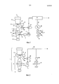
- фигура 1: схема конструкции для передачи энергии согласно изобретению, в которой подача энергии от группы APU на основной двигатель вертолета производится через электрическое взаимодействие;- figure 1: design diagram for energy transfer according to the invention, in which the energy supply from the APU group to the main engine of the helicopter is through electrical interaction;
- фигура 2: схема конструкции для передачи энергии согласно изобретению, в которой подача энергии от группы APU на основной двигатель вертолета производится через пневматическое обменное взаимодействие;- figure 2: design diagram for transmitting energy according to the invention, in which energy is supplied from the APU group to the main engine of the helicopter through a pneumatic exchange interaction;
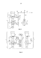
- фигура 3: схема конструкции для передачи энергии согласно изобретению, в которой подача энергии от группы APU на основной двигатель вертолета производится через механическое или гидравлическое взаимодействие;- figure 3: design diagram for energy transfer according to the invention, in which energy is supplied from the APU group to the main engine of the helicopter through mechanical or hydraulic interaction;
- фигура 4: схема конструкции для соединения APU/основные двигатели согласно изобретению в случае асимметричной работы двигателей; и- figure 4: design diagram for connecting APU / main engines according to the invention in the case of asymmetric operation of the engines; and
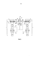
- фигура 5: схема конструкции согласно изобретению, в которой подвод энергии от основных двигателей на группу APU осуществляется через теплообменник отработанных газов.- figure 5: design diagram according to the invention, in which energy from the main engines to the APU group is supplied through an exhaust gas heat exchanger.
Подробное описание вариантов осуществленияDetailed Description of Embodiments
На всех чертежах одинаковые или близкие элементы, выполняющие одну и ту же функцию, обозначены одинаковыми или близкими позициями.In all the drawings, the same or similar elements performing the same function are denoted by the same or similar positions.
На фигуре 1 упрощенно показана схема конструкции согласно изобретению, иллюстрирующая лишь один из двух основных двигателей вертолета, причем другой двигатель является идентичным и соединен симметрично аналогичным образом с группой APU. Основные двигатели, такие как показанный основной двигатель 1, содержат газогенератор 2, образованный из системы, состоящий из компрессора 21, соединенного с камерой сгорания 22, которая сама соединена с турбиной 23. Двигатель содержит также свободную турбину 3, приводящую в действие вал силовой передачи 31. Газогенератор 2 и свободная турбина 3 находятся между воздухозаборником 4 и выпускным соплом 5.Figure 1 shows a simplified diagram of a structure according to the invention, illustrating only one of the two main engines of the helicopter, the other engine being identical and symmetrically connected in the same way to the APU group. Main engines, such as the
При работе в камеру 22 подается топливо через инжекторы 24, в которые засасывается также воздух, сжатый в компрессоре 21. Горение топливовоздушной смеси в камере 22 дает генераторные газы, обладающие высокой скоростью. Эти горячие газы расширяются сначала в турбине 23, которая автоматически приводит в действие компрессор 21 через приводной вал 25 высокого давления (HP), а затем в свободной турбине 3.During operation, fuel is supplied to the
Основной двигатель 1 передает механическую мощность на винт вертолета и на оборудование или вспомогательные агрегаты через редуктор скорости 6, в частности, на электродвигатель 61 в показанном примере, относящемся к электрической передаче мощности. Двигатель 1 передает также механическую мощность на другое оборудование или вспомогательные агрегаты через коробку 7 приводов вспомогательных агрегатов, в частности, на электродвигатель 71 в рамках данного примера. Валы 1a и 1b отбора механической мощности соединяют приводные валы 25 и валы 31 передачи с коробками 6 и 7.The
Схема конструкции с фигуры 1 показывает также группу APU 8, которая содержит, как и основные двигатели, газогенератор 81, содержащий компрессор 8a, камеру сгорания 86 и турбину 8c. Приводной вал 82 газогенератора 81 группы APU 8 соединен с электрогенератором 83, которые преобразует механическую энергию, переданную валом 82, в электрическую энергию. Ток, подаваемый в сеть вертолета 9 по проводнику 10, может затем передаваться на оборудование или вспомогательные агрегаты, установленные на редукторах 6 и коробках 7 приводов вспомогательных агрегатов основного двигателя 1. В данном примере напряжение на электродвигатели 61 и/или 71 подается через их электрическое соединение с сетью 9, питаемой от генератора 83 через избирательный блок 91.The design diagram from figure 1 also shows the APU group 8, which contains, like the main engines, a
Другой пример, проиллюстрированный схемой с фигуры 2, относится к пневматической передаче мощности. В этом случае группа APU приводит в действие нагнетатель 84, который создает поток воздуха с достаточным давлением, чтобы снабжать пневматическое оборудование. Это оборудование установлено на редукторах 6 и коробках 7 приводов вспомогательных агрегатов в механическом соединении с основным двигателем 1 через валы 1a и 1b. В данном примере вспомогательные турбины 62 и 72 кондиционирования воздуха, установленные на редукторы 6 и коробки 7 приводов вспомогательных агрегатов, снабжаются от нагнетателя 84 через воздухопроводы 20 и пневматический переключатель 92, например, трехходовой клапан. Воздух, выходящий из турбин 62 и 72, участвует, например, в вентиляции отсека двигателя, объединяющего электронное оборудование системы силовых установок вертолета.Another example illustrated by the circuit of FIG. 2 relates to pneumatic power transmission. In this case, the APU group drives the
В другом примере, проиллюстрированным схемой с фигуры 3, передача механической или гидравлической мощности осуществляется через коробку передач 11, приводимую в действие газогенератором 81 группы APU 8. Коробка передач 11 соединена через приводной вал 82 и валы 12 передачи, соединенные системой шестерен P1, промежуточной передачи R1 и системой расцепляемых зубчатых колес 93 с редуктором 6 и/или коробкой 7 приводов вспомогательных агрегатов. Эти коробки также установлены на приводных валах 25 и 31 основного двигателя 1. Энергия, поставляемая группой APU 8, позволяет привести в действие, в частности, насос или присоединенный двигатель.In another example, illustrated by the circuit of FIG. 3, mechanical or hydraulic power is transmitted through a
Предпочтительно, устройства преобразования электрической 83, пневматической 84, гидравлической и/или пневматической 11 мощности могут быть объединены в одной и той же коробке передач. Переключатель, управляемый системой FADEC группы APU (смотри описание ниже в связи с фигурой 4) и встроенный в эту коробку передач, позволяет соединиться с устройством преобразования, который доставляет желаемый тип энергии. FADEC 13 группы APU 8 управляет также, в сочетании с блоком 14 управления полетом (смотри также описание ниже в связи с фигурой 4), соединениями в режиме "и/или" систем переключения 91, 92 и 93 (фигуры 1-3) с коробками 6 и 7, соединенными с валами 31 и 25 двигателя 1 через валы отбора 1a и 1b или соединенными с таким оборудованием, как электродвигатели 61, 71 и турбины 62, 72.Preferably, the
Таким образом, группа APU способствует улучшению кпд основных двигателей и, тем самым, оптимизации удельной мощности бортовых силовых установок. Действительно, можно или увеличить имеющиеся мощности, либо уменьшить размеры и массы основных двигателей при равных имеющихся мощностях.Thus, the APU group contributes to improving the efficiency of the main engines and, thereby, optimizing the specific power of onboard power plants. Indeed, one can either increase the available capacities or reduce the sizes and masses of the main engines with equal available capacities.
Кроме того, основные двигатели вертолета могут работать в двух режимах: номинальная работа, при которой основные двигатели производят одинаковую мощность, и асимметричная работа, когда один из двигателей производит существенно большую мощность. Эта асимметричная работа может возникать, когда один из двигателей частично или полностью вышел из строя, или может вызываться намеренно, на особом этапе полетного задания вертолета, например, в случае поиска цели в особой окружающей среде.In addition, the main engines of the helicopter can operate in two modes: nominal operation, in which the main engines produce the same power, and asymmetric operation, when one of the engines produces significantly greater power. This asymmetric operation can occur when one of the engines is partially or completely out of order, or it can be called up intentionally at a special stage of the helicopter’s flight mission, for example, in the case of searching for a target in a special environment.
В случае ненамеренной асимметричной работы мощность, обеспечиваемая группой APU, может подаваться в приоритетном порядке к частично неисправному двигателю в целях восстановления равновесия тяги. В случае намеренной асимметрии работы мощность, обеспечиваемая группой APU, передается на нагруженный двигатель в целях облегчения его нагрузки. Во всех случаях асимметричной работы, как иллюстрирует схема на фигуре 4, группа APU 8 и основные двигатели 1 и 1' имеют блоки 13 цифрового управления типа FADEC, которые передают информацию, относящуюся к крутящим моментам и скоростям приводных валов и валов силовой передачи 25, 25', 31, 31', 82. Эта информация централизованно собирается на уровне блоков 14 управления полетом, чтобы регулировать передачу мощности от группы APU 8 на основные двигатели 1, 1' и на их оборудование через системы переключения 91, 92, 93, а также на валы отбора 1a и 1b, в зависимости от рабочего состояния каждого из основных двигателей относительно заданных значений крутящих моментов и скоростей.In the case of unintentional asymmetric operation, the power provided by the APU can be given priority to a partially faulty engine in order to restore traction balance. In case of intentional asymmetry of operation, the power provided by the APU group is transferred to the loaded engine in order to facilitate its load. In all cases of asymmetric operation, as the diagram in figure 4 illustrates, the APU group 8 and the
В случае полного отказа одного из двигателей (особый режим OEI - акроним от английского термина "one engine inoperative", то есть один отказавший двигатель), мощность от группы APU в приоритетном порядке используется для попыток повторного запуска этого двигателя. В случае намеренной асимметрии работы мощность группы APU предназначена в первую очередь для облегчения работы наиболее нагруженного двигателя.In the event of a complete failure of one of the engines (a special OEI mode is an acronym for the English term "one engine inoperative", that is, one failed engine), the power from the APU group is used as a priority for attempts to restart this engine. In the case of intentional asymmetry of operation, the power of the APU group is primarily intended to facilitate the operation of the most loaded engine.
Чтобы оптимизировать удельный расход системы силовых установок APU/основные двигатели или, более обобщенно, газовая турбина/основные двигатели, можно также предусмотреть рекуперацию тепловой энергии на выпуске в комбинации с подводом энергии от группы APU на основные двигатели через валы отбора 1a и 1b. Как показано схемой на фигуре 5, каждое выпускное сопло 5 и 5' основных двигателей 1 и 1' содержит теплообменник 15, 15'. Эти теплообменники рекуперируют, по меньшей мере, довольно значительную часть тепловой энергии отработанного газа.In order to optimize the specific consumption of the APU propulsion system / main engines or, more generally, the gas turbine / main engines, it is also possible to provide for the recovery of thermal energy at the outlet in combination with the supply of energy from the APU group to the main engines through the
Текучая среда рекуперации энергии, которая циркулирует в теплообменниках 15 и 15', отбирается на выходе компрессора 8a группы APU 8 и снова вводится непосредственно выше по потоку от камеры сгорания 8b. Линии 80a и 80b обеспечивают циркуляцию текучей среды между теплообменниками 15, 15' и газогенератором 81 группы APU 8.The energy recovery fluid that circulates in the
В этих условиях, при одинаковых характеристиках, подвод тепла, обеспечиваемый сжиганием топлива в группе APU, можно уменьшить, так как это уменьшение компенсируется подводом тепла, поступающим из теплообменников 15 и 15'. Таким образом, потребность системы силовых установок в топливе снижается. Это снижение потребности в топливе может быть выгодным в установившемся режиме полета, например, на этапах крейсерского полета, являющихся обычно самыми длительными этапами.Under these conditions, with the same characteristics, the heat supply provided by the combustion of fuel in the APU group can be reduced, since this decrease is compensated by the heat supply coming from the
Когда рекуперация тепловой энергии особенно высокая, можно прекратить нагнетание топлива в камеру сгорания группы APU 8. В этом случае единственным источником тепла группы APU является тепло, отбираемое у отработанных газов основных двигателей 1 и 1' в теплообменниках 15 и 15'. В этом случае оптимизация энергии системы силовых установок максимальна.When the recovery of thermal energy is particularly high, it is possible to stop the injection of fuel into the combustion chamber of the APU group 8. In this case, the only heat source of the APU group is the heat taken from the exhaust gases of the
Изобретение не ограничено описанными и проиллюстрированными примерами.The invention is not limited to the described and illustrated examples.
Можно, например, применять изобретение к основным двигателям со связанной турбиной, соединяя приводной вал группы APU или, более обобщенно, вспомогательного двигателя, с оборудованием и вспомогательными агрегатами, соединенными напрямую с приводными валами основных двигателей со связанными турбинами, или через редукторы и/или коробки приводов вспомогательных агрегатов. Применимость термина "вспомогательный двигатель" распространяется на двигатели с технологией, отличной от технологии газовой турбины (например, дизельный двигатель, топливный элемент и т.д.). Таким образом, этот вспомогательный двигатель может быть двигателем трехтурбинного вертолета с меньшими размерами и более низкими характеристиками, чем у двух других основных двигателей.You can, for example, apply the invention to main engines with a connected turbine, connecting the drive shaft of the APU group or, more generally, the auxiliary engine, with equipment and auxiliary units connected directly to the drive shafts of the main engines with connected turbines, or through gearboxes and / or boxes drives of auxiliary units. The applicability of the term "auxiliary engine" extends to engines with technology other than gas turbine technology (eg, diesel engine, fuel cell, etc.). Thus, this auxiliary engine can be the engine of a three-turbine helicopter with smaller dimensions and lower characteristics than the other two main engines.
Claims (10)
Applications Claiming Priority (3)
| Application Number | Priority Date | Filing Date | Title |
|---|---|---|---|
| FR1255599 | 2012-06-15 | ||
| FR1255599A FR2992024B1 (en) | 2012-06-15 | 2012-06-15 | METHOD AND ARCHITECTURE OF OPTIMIZED ENERGY TRANSFER BETWEEN AN AUXILIARY POWER MOTOR AND THE MAIN ENGINES OF A HELICOPTER |
| PCT/FR2013/051376 WO2014009620A1 (en) | 2012-06-15 | 2013-06-12 | Method and architecture for the optimized transfer of power between an auxiliary power motor and the main engines of a helicopter |
Publications (2)
| Publication Number | Publication Date |
|---|---|
| RU2014150999A RU2014150999A (en) | 2016-08-10 |
| RU2629621C2 true RU2629621C2 (en) | 2017-08-30 |
Family
ID=47049238
Family Applications (1)
| Application Number | Title | Priority Date | Filing Date |
|---|---|---|---|
| RU2014150999A RU2629621C2 (en) | 2012-06-15 | 2013-06-12 | Method and structure of optimized power transmission between auxiliary power engine and main engine of helicopter |
Country Status (12)
| Country | Link |
|---|---|
| US (1) | US10059460B2 (en) |
| EP (1) | EP2861493B1 (en) |
| JP (1) | JP6313756B2 (en) |
| KR (1) | KR102097841B1 (en) |
| CN (1) | CN104379450B (en) |
| CA (1) | CA2874962C (en) |
| ES (1) | ES2698953T3 (en) |
| FR (1) | FR2992024B1 (en) |
| IN (1) | IN2014DN10616A (en) |
| PL (1) | PL2861493T3 (en) |
| RU (1) | RU2629621C2 (en) |
| WO (1) | WO2014009620A1 (en) |
Families Citing this family (29)
| Publication number | Priority date | Publication date | Assignee | Title |
|---|---|---|---|---|
| FR2986780B1 (en) * | 2012-02-13 | 2014-11-14 | Motorisations Aeronautiques | DEVICE FOR SUPPLYING AIR FROM AN AUXILIARY POWER UNIT OF AN AIRCRAFT, AIRCRAFT |
| FR2992630B1 (en) * | 2012-06-29 | 2015-02-20 | Turbomeca | METHOD AND CONFIGURATION OF PROPULSIVE AND / OR NON-PROPULSIVE ENERGY DELIVERY IN A HELICOPTER ARCHITECTURE BY A POWER AUXILIARY ENGINE |
| US8939399B2 (en) | 2012-07-31 | 2015-01-27 | Textron Innovations Inc. | System and method of augmenting power in a rotorcraft |
| EP2994386B1 (en) | 2013-05-06 | 2020-02-19 | Sikorsky Aircraft Corporation | Supplemental power for reduction of prime mover |
| FR3008679B1 (en) * | 2013-07-16 | 2015-08-14 | Eurocopter France | MODULAR AND AIRCRAFT POWER PLANT WITH SUSTENTATION ROTOR |
| FR3019224B1 (en) * | 2014-03-27 | 2016-03-18 | Turbomeca | METHOD FOR ASSISTING A MULTI-ENGINE HELICOPTER SLEEPING TURBOMOTEUR AND ARCHITECTURE OF A PROPELLANT HELICOPTER SYSTEM COMPRISING AT LEAST ONE TURBOMOTEUR WHICH CAN BE ON SLEEP |
| FR3019218B1 (en) | 2014-03-27 | 2016-03-18 | Turbomeca | ARCHITECTURE OF A PROPULSIVE SYSTEM OF A MULTI-ENGINE HELICOPTER AND CORRESPONDING HELICOPTER |
| FR3019219B1 (en) * | 2014-03-27 | 2016-03-18 | Turbomeca | ARCHITECTURE OF A PROPULSIVE SYSTEM OF A MULTI-ENGINE HELICOPTER AND CORRESPONDING HELICOPTER |
| FR3019220A1 (en) * | 2014-03-27 | 2015-10-02 | Turbomeca | METHOD FOR ALTERNATE RESTART OF A HELICOPTER SLEEPING TURBOMOTE AND MULTI-ENGINE ARCHITECTURE FOR IMPLEMENTING SUCH A METHOD |
| FR3019358B1 (en) * | 2014-03-27 | 2016-03-18 | Turbomeca | METHOD FOR OPTIMIZED GLOBAL MANAGEMENT OF AN AIRCRAFT ENERGY NETWORK AND CORRESPONDING DEVICE |
| FR3019588B1 (en) * | 2014-04-08 | 2019-06-14 | Safran Helicopter Engines | DEVICE FOR ASSISTING A SOLID PROPERGOL PROPULSIVE SYSTEM OF A MONOMOTING HELICOPTER, MONOMOTOR HELICOPTER COMPRISING SUCH DEVICE AND CORRESPONDING METHOD |
| US10066547B2 (en) * | 2014-07-01 | 2018-09-04 | United Technologies Corporation | Combined two engine cycle with at least one recuperated cycle engine for rotor drive |
| FR3024180B1 (en) * | 2014-07-28 | 2016-07-22 | Turbomeca | PNEUMATIC DEVICE FOR RAPID REACTIVATION OF A TURBOMOTEUR, ARCHITECTURE OF A PROPULSIVE SYSTEM OF A MULTI-ENGINE HELICOPTER EQUIPPED WITH SUCH A DEVICE AND CORRESPONDING HELICOPTER |
| FR3026435B1 (en) * | 2014-09-29 | 2016-10-21 | Turbomeca | DEVICE AND METHOD FOR INTEGRITY TESTING OF A RAPID REACTIVATION SYSTEM OF A TURBOMOTOR OF A HELICOPTER |
| FR3031500B1 (en) | 2015-01-12 | 2017-01-13 | Turbomeca | DEVICE AND METHOD FOR CONTROLLING AN AUXILIARY ENGINE ADAPTED TO PROVIDE PROPELLANT POWER TO THE ROTOR OF A HELICOPTER |
| FR3036235B1 (en) | 2015-05-15 | 2018-06-01 | Airbus Helicopters | METHOD FOR ACTIVATING AN ELECTRIC MOTOR OF A HYBRID INSTALLATION OF A MULTI-ENGINE AIRCRAFT AND AN AIRCRAFT |
| FR3043724A1 (en) * | 2015-11-16 | 2017-05-19 | Snecma | METHOD OF DIMENSIONING A PROPULSIVE ASSEMBLY COMPRISING A MAIN ENGINE AND AN AUXILIARY ENGINE |
| US10723452B2 (en) * | 2017-02-15 | 2020-07-28 | Sikorsky Aircraft Corporation | Engine systems for rotorcraft |
| US10393017B2 (en) * | 2017-03-07 | 2019-08-27 | Rolls-Royce Corporation | System and method for reducing specific fuel consumption (SFC) in a turbine powered aircraft |
| FR3078057B1 (en) * | 2018-02-19 | 2022-04-22 | Safran Helicopter Engines | PROPULSION SYSTEM ARCHITECTURE OF A TWIN-ENGINE HELICOPTER |
| US11415044B2 (en) * | 2018-06-19 | 2022-08-16 | Raytheon Technologies Corporation | Multi-engine architecture with linkages to multiple spools |
| CN109339952B (en) * | 2018-09-29 | 2020-01-21 | 北京航空航天大学 | Engine starting system and airborne energy management system of helicopter |
| US10954863B2 (en) | 2019-04-09 | 2021-03-23 | General Electric Company | Phasing gearbox |
| US11663863B2 (en) | 2019-06-07 | 2023-05-30 | Pratt & Whitney Canada Corp. | Methods and systems for operating a rotorcraft |
| US11479348B2 (en) * | 2019-08-31 | 2022-10-25 | Textron Innovations Inc. | Power management systems for multi engine rotorcraft |
| RU2729311C1 (en) * | 2020-01-29 | 2020-08-05 | Борис Яппарович Альмухаметов | Hybrid turbofan plant with built-in rotor ice |
| US11608189B2 (en) * | 2020-08-11 | 2023-03-21 | Textron Innovations Inc | Multistage infrared suppression exhaust system |
| US11434824B2 (en) | 2021-02-03 | 2022-09-06 | General Electric Company | Fuel heater and energy conversion system |
| CN113323757B (en) * | 2021-06-01 | 2022-12-20 | 北京清软创想信息技术有限责任公司 | Disconnect-type atmospheric pressure type auxiliary power air piping system |
Citations (5)
| Publication number | Priority date | Publication date | Assignee | Title |
|---|---|---|---|---|
| US3963372A (en) * | 1975-01-17 | 1976-06-15 | General Motors Corporation | Helicopter power plant control |
| EP0490755A1 (en) * | 1990-12-12 | 1992-06-17 | AEROSPATIALE Société Nationale Industrielle | Power drive between a drive shaft and two driven units, in particular for rotor-powered aircraft |
| RU2224686C1 (en) * | 2003-04-07 | 2004-02-27 | Открытое акционерное общество "Казанский вертолетный завод" | Helicopter |
| GB2460246A (en) * | 2008-05-21 | 2009-11-25 | Matthew P Wood | A helicopter emergency power system |
| RU2418721C2 (en) * | 2005-09-29 | 2011-05-20 | Эйрбас Дойчланд Гмбх | Electric power supply system for, at least, one aircraft electric power consumer |
Family Cites Families (8)
| Publication number | Priority date | Publication date | Assignee | Title |
|---|---|---|---|---|
| US3455182A (en) * | 1967-04-12 | 1969-07-15 | Garrett Corp | Helicopter lift augmentation means |
| US5054716A (en) * | 1989-10-16 | 1991-10-08 | Bell Helicopter Textron Inc. | Drive system for tiltrotor aircraft |
| US5239830A (en) * | 1992-03-05 | 1993-08-31 | Avco Corporation | Plural engine power producing system |
| US6098921A (en) * | 1999-05-06 | 2000-08-08 | Piasecki Aircraft Corp. | Rotary wing aircraft supplementary power drive system |
| GB0714924D0 (en) * | 2007-08-01 | 2007-09-12 | Rolls Royce Plc | An engine arrangement |
| FR2962488B1 (en) | 2010-07-06 | 2014-05-02 | Turbomeca | METHOD AND ARCHITECTURE OF TURBOMACHINE POWER RECOMBINATION |
| US8845898B2 (en) * | 2010-07-07 | 2014-09-30 | Hamilton Sundstrand Corporation | APU fuel filter housing scupper |
| US8684304B2 (en) * | 2010-11-16 | 2014-04-01 | Rolls-Royce Corporation | Aircraft, propulsion system, and system for taxiing an aircraft |
-
2012
- 2012-06-15 FR FR1255599A patent/FR2992024B1/en active Active
-
2013
- 2013-06-12 EP EP13733392.8A patent/EP2861493B1/en active Active
- 2013-06-12 PL PL13733392T patent/PL2861493T3/en unknown
- 2013-06-12 JP JP2015516667A patent/JP6313756B2/en not_active Expired - Fee Related
- 2013-06-12 ES ES13733392T patent/ES2698953T3/en active Active
- 2013-06-12 RU RU2014150999A patent/RU2629621C2/en active
- 2013-06-12 CA CA2874962A patent/CA2874962C/en not_active Expired - Fee Related
- 2013-06-12 US US14/406,054 patent/US10059460B2/en active Active
- 2013-06-12 CN CN201380030989.4A patent/CN104379450B/en active Active
- 2013-06-12 KR KR1020147034957A patent/KR102097841B1/en active IP Right Grant
- 2013-06-12 WO PCT/FR2013/051376 patent/WO2014009620A1/en active Application Filing
- 2013-06-12 IN IN10616DEN2014 patent/IN2014DN10616A/en unknown
Patent Citations (5)
| Publication number | Priority date | Publication date | Assignee | Title |
|---|---|---|---|---|
| US3963372A (en) * | 1975-01-17 | 1976-06-15 | General Motors Corporation | Helicopter power plant control |
| EP0490755A1 (en) * | 1990-12-12 | 1992-06-17 | AEROSPATIALE Société Nationale Industrielle | Power drive between a drive shaft and two driven units, in particular for rotor-powered aircraft |
| RU2224686C1 (en) * | 2003-04-07 | 2004-02-27 | Открытое акционерное общество "Казанский вертолетный завод" | Helicopter |
| RU2418721C2 (en) * | 2005-09-29 | 2011-05-20 | Эйрбас Дойчланд Гмбх | Electric power supply system for, at least, one aircraft electric power consumer |
| GB2460246A (en) * | 2008-05-21 | 2009-11-25 | Matthew P Wood | A helicopter emergency power system |
Also Published As
| Publication number | Publication date |
|---|---|
| FR2992024A1 (en) | 2013-12-20 |
| PL2861493T3 (en) | 2019-03-29 |
| US10059460B2 (en) | 2018-08-28 |
| KR102097841B1 (en) | 2020-04-06 |
| RU2014150999A (en) | 2016-08-10 |
| FR2992024B1 (en) | 2017-07-21 |
| CA2874962A1 (en) | 2014-01-16 |
| EP2861493B1 (en) | 2018-10-17 |
| JP2015525321A (en) | 2015-09-03 |
| CN104379450B (en) | 2017-05-31 |
| CA2874962C (en) | 2021-03-30 |
| US20150122944A1 (en) | 2015-05-07 |
| JP6313756B2 (en) | 2018-04-18 |
| CN104379450A (en) | 2015-02-25 |
| EP2861493A1 (en) | 2015-04-22 |
| WO2014009620A1 (en) | 2014-01-16 |
| KR20150030203A (en) | 2015-03-19 |
| IN2014DN10616A (en) | 2015-09-11 |
| ES2698953T3 (en) | 2019-02-06 |
Similar Documents
| Publication | Publication Date | Title |
|---|---|---|
| RU2629621C2 (en) | Method and structure of optimized power transmission between auxiliary power engine and main engine of helicopter | |
| US10301035B2 (en) | Method and configuration for an auxiliary power engine to deliver propulsive and/or non-propulsive energy in a helicopter architecture | |
| EP3002435B1 (en) | Accessory drive system for a gas turbine engine | |
| EP2452878B1 (en) | Propulsion system for an aircraft, aircraft and method of operating a propulsion system | |
| US9885289B2 (en) | Aircraft propulsion architecture integrating an energy recovery system | |
| US9422863B2 (en) | Method and architecture for recombining the power of a turbomachine | |
| US10428739B2 (en) | Self-contained power unit for implementing a method for optimizing the operability of an aircraft propulsive unit | |
| US20200355121A1 (en) | Bleed expander cooling with turbine | |
| EP2452876B1 (en) | Aircraft propulsion system and system for taxiing an aircraft | |
| US11535392B2 (en) | Architectures for hybrid-electric propulsion | |
| CN107979116A (en) | Method for distributing electric power in power system architectures | |
| EP2452879B1 (en) | Propulsion system for an aircraft | |
| JP2012503569A (en) | Output distribution system | |
| US11732639B2 (en) | Mechanical disconnects for parallel power lanes in hybrid electric propulsion systems | |
| CN110481803B (en) | aircraft propulsion system | |
| US11708792B2 (en) | Twin-engine system with electric drive |
Legal Events
| Date | Code | Title | Description |
|---|---|---|---|
| PD4A | Correction of name of patent owner | ||
| PD4A | Correction of name of patent owner |