EP4477256A1 - Schönheitspflegeinstrument - Google Patents
Schönheitspflegeinstrument Download PDFInfo
- Publication number
- EP4477256A1 EP4477256A1 EP24758129.1A EP24758129A EP4477256A1 EP 4477256 A1 EP4477256 A1 EP 4477256A1 EP 24758129 A EP24758129 A EP 24758129A EP 4477256 A1 EP4477256 A1 EP 4477256A1
- Authority
- EP
- European Patent Office
- Prior art keywords
- electrode
- electrodes
- sub
- main housing
- skin
- Prior art date
- Legal status (The legal status is an assumption and is not a legal conclusion. Google has not performed a legal analysis and makes no representation as to the accuracy of the status listed.)
- Granted
Links
Images


Classifications
-
- A—HUMAN NECESSITIES
- A45—HAND OR TRAVELLING ARTICLES
- A45D—HAIRDRESSING OR SHAVING EQUIPMENT; EQUIPMENT FOR COSMETICS OR COSMETIC TREATMENTS, e.g. FOR MANICURING OR PEDICURING
- A45D44/00—Other cosmetic or toiletry articles, e.g. for hairdressers' rooms
- A45D44/22—Face shaping devices, e.g. chin straps; Wrinkle removers, e.g. stretching the skin
-
- A—HUMAN NECESSITIES
- A61—MEDICAL OR VETERINARY SCIENCE; HYGIENE
- A61N—ELECTROTHERAPY; MAGNETOTHERAPY; RADIATION THERAPY; ULTRASOUND THERAPY
- A61N1/00—Electrotherapy; Circuits therefor
- A61N1/02—Details
- A61N1/04—Electrodes
-
- A—HUMAN NECESSITIES
- A61—MEDICAL OR VETERINARY SCIENCE; HYGIENE
- A61N—ELECTROTHERAPY; MAGNETOTHERAPY; RADIATION THERAPY; ULTRASOUND THERAPY
- A61N1/00—Electrotherapy; Circuits therefor
- A61N1/02—Details
- A61N1/04—Electrodes
- A61N1/0404—Electrodes for external use
- A61N1/0408—Use-related aspects
- A61N1/0452—Specially adapted for transcutaneous muscle stimulation [TMS]
-
- A—HUMAN NECESSITIES
- A61—MEDICAL OR VETERINARY SCIENCE; HYGIENE
- A61N—ELECTROTHERAPY; MAGNETOTHERAPY; RADIATION THERAPY; ULTRASOUND THERAPY
- A61N1/00—Electrotherapy; Circuits therefor
- A61N1/02—Details
- A61N1/04—Electrodes
- A61N1/0404—Electrodes for external use
- A61N1/0472—Structure-related aspects
- A61N1/0476—Array electrodes (including any electrode arrangement with more than one electrode for at least one of the polarities)
-
- A—HUMAN NECESSITIES
- A61—MEDICAL OR VETERINARY SCIENCE; HYGIENE
- A61N—ELECTROTHERAPY; MAGNETOTHERAPY; RADIATION THERAPY; ULTRASOUND THERAPY
- A61N1/00—Electrotherapy; Circuits therefor
- A61N1/18—Applying electric currents by contact electrodes
-
- A—HUMAN NECESSITIES
- A61—MEDICAL OR VETERINARY SCIENCE; HYGIENE
- A61N—ELECTROTHERAPY; MAGNETOTHERAPY; RADIATION THERAPY; ULTRASOUND THERAPY
- A61N1/00—Electrotherapy; Circuits therefor
- A61N1/18—Applying electric currents by contact electrodes
- A61N1/32—Applying electric currents by contact electrodes alternating or intermittent currents
- A61N1/328—Applying electric currents by contact electrodes alternating or intermittent currents for improving the appearance of the skin, e.g. facial toning or wrinkle treatment
-
- A—HUMAN NECESSITIES
- A61—MEDICAL OR VETERINARY SCIENCE; HYGIENE
- A61N—ELECTROTHERAPY; MAGNETOTHERAPY; RADIATION THERAPY; ULTRASOUND THERAPY
- A61N1/00—Electrotherapy; Circuits therefor
- A61N1/18—Applying electric currents by contact electrodes
- A61N1/32—Applying electric currents by contact electrodes alternating or intermittent currents
- A61N1/36—Applying electric currents by contact electrodes alternating or intermittent currents for stimulation
- A61N1/36014—External stimulators, e.g. with patch electrodes
Definitions
- Embodiments of the disclosure relate to the technical field of medical beauty, in particular to a beauty instrument.
- a beauty instrument is an instrument for regulating and improving skin conditions, which can help people to whiten, tenderize skin, remove spots and the like, and enables the skin to be tender, glossy, and elastic.
- the beauty instrument stimulates and acts on the skin by way of micro-frequency current, radio frequency, ultrasonic wave, and strong light, to improve skin metabolism, contract muscles, and realize a beauty function. It can also facilitate effective ingredients in skin care products to enter deep layers of the skin so as to be more easily absorbed and utilized by the skin, and function better in beautifying.
- Electrodes may be provided on a care head of the beauty instrument to care for the skin by way of micro-frequency current or radio frequency.
- the electrodes on the care head are in contact with and discharges to the skin, thus realizing care effect.
- the electrodes on the care head are usually block electrodes with a large area, and a large interval is kept between the block electrodes to avoid short circuit.
- users can obviously feel parts with the electrodes and those without the electrodes on the care head, thus the care experience is not good.
- a beauty instrument is provided in the present disclosure, which can prevent users from obviously feeling an electrode provision area on a care head, improving discharge uniformity and care experience.
- a beauty instrument includes:
- the plurality of dot electrodes are parallel to each other.
- the plurality of first electrodes include a first sub-electrode and a second sub-electrode which have opposite polarities and form an electrode pair, and at least part of the plurality of dot electrodes are arranged between the first sub-electrode and the second sub-electrode in an array.
- the first sub-electrode is arranged at the end of the main housing and closing to a middle area of the main housing, and the second sub-electrode is arranged at an edge of the end of the main housing, and at least part of the second sub-electrode extends to a side of the main housing.
- the plurality of first electrodes include two second sub-electrodes, and each second sub-electrode is located at one side edge of two side edges of the main housing.
- the first sub-electrode is arranged between the two second sub-electrodes, and each of the two second sub-electrodes and the first sub-electrode have opposite polarities and form an electrode pair.
- the dot electrodes in an array are arranged between each of the two second sub-electrodes and the first sub-electrode.
- the electrode assembly further includes: a second electrode arranged between the two second sub-electrodes and including a first arc-shaped electrode and a second arc-shaped electrode, the first arc-shaped electrode and the second arc-shaped electrode have opposite polarities and form an electrode pair.
- the first arc-shaped electrode is arranged at the edge of the end of the main housing, and at least part of the first arc-shaped electrode extends to the side of the main housing.
- the two second sub-electrodes and the second electrode surround the plurality of dot electrodes.
- a part of the plurality of dot electrodes are arranged between at least one end of the first sub-electrode in a longitudinal direction and the edge of the end of the main housing.
- the elongated first electrodes act on the skin in a large area and discharge, and the dot electrodes between the elongated first electrodes are used to uniformly discharge on the skin in the area between the first electrodes, so that user is prevented from obviously feeling the electrode provision area on the care head.
- a caring area of the electrodes of the beauty instrument is increased, and care experience and efficiency are also improved.
- different electrodes can act on the skin in different areas, thereby further expanding application scenes and meeting care needs of different skin areas.
- first and second are only configured for descriptive purposes and cannot be understood as indicating or implying a relative importance, or implicitly indicating a number of indicated technical features. Therefore, the features defined with “first” and “second” can explicitly or implicitly include at least one of these features. In description of this present disclosure, "a plurality of” means at least two, such as two, three, etc., unless otherwise specifically defined.
- a beauty instrument in an embodiment of the present disclosure, which includes an operating part 100 for a user to hold and grip and a performing part 200 for performing skin care.
- the user can hold the operating part 100 and face the performing part 200 towards skin so as to perform the skin care.
- an electrode and/or a therapy lamp can be provided at an end of the performing part 200, and the performing part 200 can contact a skin surface and move back and forth on the skin surface, so as to achieve effect such as skin rejuvenation and beauty.
- the operating part 100 includes a front housing 10, a rear housing 20, and a middle housing assembly 30.
- the front housing 10 and the rear housing 20 are respectively fixed to the middle housing assembly 30 from one side of two opposite sides of the middle housing assembly 30, to define an accommodation for accommodating internal electrical components such as circuits and wirings.
- the middle housing assembly 30 may be provided with a button (not shown) that can be operated and pressed by the user, so as to realize operations of switching functions of the beauty instrument or turning on and off of the power supply, or the middle housing assembly 30 may be provided with an indicator lamp that indicates an operation state of the beauty instrument.
- the operating part 100 of the beauty instrument includes two grip parts 101 with each being arranged on one side of two opposite sides of the operating part 100 in a thickness direction X, and the grip parts 101 are configured for being held by users.
- the performing part 200 includes a main housing 210 and an electrode assembly 220.
- the main housing 210 is connected with the operating part 100, and the electrode assembly 220 is arranged and fixed to the main housing 210.
- the electrode assembly 220 includes an elongated first electrode 221.
- the first electrode 221 is at least partially exposed on the main housing 210, and an extending direction Y of the first electrode 221 is consistent with a direction perpendicular to a thickness direction X of the operating part 100.
- the extending direction Y of the first electrode 221 is basically perpendicular to the thickness direction X of the operating part 100, so that the two grip parts 101 are arranged at intervals in the extending direction which is basically perpendicular to the first electrode 221, which facilitates to guiding the user to move the beauty instrument along the extending direction Y of the first electrode 221.
- "Basically perpendicular” can be understood as vertical, or there is small deviation from a vertical state, for example with a deviation angle from the vertical direction within ⁇ 15°.
- the electrode is exposed on the housing, which may include a situation that the electrode is convexly provided at a surface of the housing, a situation that a surface of the electrode is flush with a surface of the housing, or a situation that a groove is defined in the surface of the housing, the electrode is accommodated in the groove, and the surface of the housing protrudes from the surface of the electrode, as long as the electrode can discharge to the skin during contact between the housing and the skin.
- the operating part 100 is flat in shape, with a length direction perpendicular to its thickness direction.
- each of the grip part 101 is arranged on flat surface at one side of both sides of the operating part 100.
- the first electrode 221 Since the extending direction Y of the first electrode 221 is basically perpendicular to the thickness direction X of the operating part 100, the first electrode 221 extends basically along the length direction of the operating part 100, so that when the beauty instrument is pushed along the skin surface, the length direction of the first electrode 221 is consistent with a moving direction of the beauty instrument, and the first electrode 221 moves on the skin surface along a pushing direction of the beauty instrument, which can reduce foreign body sensation on the skin surface of the user during operations of the beauty instrument and realize more comfortable care experience.
- the operating part of the beauty instrument is provided with an elongated first electrode.
- the user holds the grip parts of the operating part and pushes the beauty instrument to move on the skin surface to perform skin care.
- the extending direction of the first electrode is basically perpendicular to the thickness direction of the operating part, the extending direction of the first electrode is consistent with the moving direction of the beauty instrument during movement of the beauty instrument, thus the user may not feel the foreign body sensation at care sites, and the elongated electrode ensures a contact area of the electrode with the skin, thus improving care efficiency and ensuring care experience.
- a shape of the first electrode is provided to be matched with a setting of the grip part so as to guide the user to move the beauty instrument, thus fully using advantages of the strip electrode and improving the care efficiency and experience.
- the grip part 101 includes concave parts formed on a side of the operating part 100, and each of the concave parts may extend along the length direction of the first electrode 221.
- the grip part 101 can also be provided as a profiling concave part matched with a human hand.
- the grip part 101 includes a first concave part corresponding to an arc contour of a human palm and a second concave part corresponding to a contour of a human knuckle. Due to provision of the profiling concave part, a contact area between a side surface of the operating part 100 and the human hand is increased, and the user can hold it more firmly.
- the first electrodes 221 include a first sub-electrode 2211 and a second sub-electrode 2212 arranged at intervals in the thickness direction X of the operating part 100.
- the first sub-electrode 2211 and the second sub-electrode 2212 have opposite polarities and form an electrode pair.
- the first electrodes 221 are parallel to each other, that is, extending directions of the first electrodes 221 are the same.
- the first sub-electrode 2211 and the second sub-electrode 2212 are in contact with the skin at the same time, thus forming a loop and generating a current at a contact site with the skin, for example, a micro current or radio frequency current, to perform skin care.
- the electrode assembly 220 further includes a plurality of dot electrodes 222 arranged at intervals, and at least part of the dot electrodes 222 are arranged in an array between the first sub-electrode 2211 and the second sub-electrode 2212, and an end of each of the dot electrodes 222 is exposed on an end of the main housing 210.
- the dot electrodes 222 are configured to perform skin care by generating micro current or radio frequency current.
- the electrode assembly 220 includes a plurality of rows of dot electrodes 222 arranged side by side, and two adjacent dot electrodes 222 among each row of dot electrodes 222 have opposite polarities and form an electrode pair.
- the electrode assembly 220 includes a plurality of rows of dot electrodes 222 arranged along the extending direction Y of the first electrode 221, and two adjacent dot electrodes 222 among each row of dot electrodes 222 have opposite polarities and form an electrode pair.
- the two adjacent dot electrodes 222 among each row of dot electrodes 222 contact the skin at the same time, they can form a loop, thereby discharging to the skin.
- electrode pairs of the dot electrodes 222 is not limited to this.
- two adjacent dot electrodes 222 in a direction perpendicular to the row of the dot electrodes 222 have opposite polarities and form an electrode pair.
- an area of each of the dot electrodes 222 is small, but there are a larger number of dot electrodes, and a cross section of the dot electrode 222 may be circular or elliptical.
- the dot electrodes 222 output a radio frequency current for skin care.
- a large number of dot electrodes 222 are configured to contact with the skin, thus discharging to the skin.
- an effective contact area between the dot electrodes 222 and the skin is larger. For example, in areas with curvature such as mandible, the electrodes in array are more conducive to contact with the skin than the large-area electrodes.
- the decentralized electrodes due to decentralized arrangement of the dot electrodes 222, on a premise of a same electrode area, the decentralized electrodes have a larger skin action area than the large-area electrodes, with more uniform radio frequency energy distribution. It can be understood that in other embodiments, a micro current can also be output through the dot electrode 222 for the skin care.
- the main housing 210 includes an end and a side.
- the electrodes at the end of the main housing 210 can discharge to the skin with flat area, and the electrodes at the side of the main housing 210 can discharge to the local skin.
- the first sub-electrode 2211 is arranged at the end of the main housing 210 and closing to a middle area of the main housing, and the second sub-electrode 2212 is arranged at an edge of the end of the main housing 210 and partially extends to the side of the main housing 210.
- the first sub-electrode 2211, the second sub-electrode 2212, and the dot electrodes 222 can serve to perform skin care for large flat area, for example, by generating a micro current to act on the skin to achieve skin resurfacing effect.
- the second sub-electrode 2212 can serve to perform care for an uneven skin surface.
- the second sub-electrode 2212 may be in contact with an edge of the nose to discharge to the skin around the nose.
- the first electrodes 221 include two second sub-electrodes 2212, with each second sub-electrode 2212 being located at one side edge of two side edges of the main housing 210 in the thickness direction X of the operating part 100.
- the first sub-electrode 2211 is arranged between the two second sub-electrodes 2212, and each of the two second sub-electrodes 2212 and the first sub-electrode 2211 have opposite polarities and form an electrode pair.
- the first sub-electrode 2211 and a corresponding second sub-electrode 2212 are in contact with the skin at the same time, they can form a loop and thus discharge to the skin.
- the second sub-electrodes 2212 at the two sides can serve to respectively perform care for skin in different areas, thus expanding application scenarios.
- dot electrodes 222 may be arranged between the second sub-electrodes 2212 at the two sides and the first sub-electrode 2211 at the middle, and the dot electrodes 222 can cooperate with the first sub-electrode 2211 and the second sub-electrode 2212 of the first electrodes 221, so that the first sub-electrode 2211 and the second sub-electrode 2212 discharge to skin at an edge of a target area, while the dot electrodes 222 discharge to skin between the first sub-electrode 2211 and the first sub-electrode 2212, thus further expanding application scenarios and meeting care needs of different skin areas.
- the two second sub-electrodes 2212 are respectively located at two side edges of the main housing 210 in the thickness direction X of the operating part 100, a distance between the second sub-electrode 2212 and the first sub-electrode 2211 can be maximized, so that a current sensation felt by the user is weakest during the second sub-electrode 2212 and the first sub-electrode 2211 are in contact with the skin and discharging, and thus comfort of care experience is improved to a maximum extent.
- the beauty instrument when it needs to achieve skin tightening effect for large-area skin, the beauty instrument can operate in a pulling mode and discharge to the large-area skin.
- the first electrode 221 and the dot electrode 222 output a radio frequency current at the same time, or the first electrode 221 outputs a micro current, or the first electrode 221 and the dot electrode 222 output a radio frequency current at the same time for a period of time and then the first electrode 221 outputs a micro current for a period of time, and these two manners are alternately adopted to discharge to the skin.
- the first electrodes 221 and the dot electrodes 222 can be combined and configured to alternately output the micro current and the radio frequency current, so that it is not easy for users to perceive change in current.
- the first electrodes 221 and the dot electrodes 222 can be combined and alternately energized with a micro current and a radio frequency current, and after care for each area for a period of time, care can be performed for another care area, and in this process, it is not easy for users to perceive change in current.
- the electrode assembly 220 further includes a second electrode 223, and the second electrode 223 includes a first arc-shaped electrode 2231 and a second arc-shaped electrode 2232, which have opposite polarities and form an electrode pair.
- areas of the first arc-shaped electrode 2231 and the second arc-shaped electrode 2232 are both larger than that of the dot electrode 222.
- the first arc-shaped electrode 2231 is disposed at the edge of the end of the main housing 210 and partially extends to the side of the main housing 210
- the second arc-shaped electrode 2232 is disposed at the end of the main housing 210 and closing to the first arc-shaped electrode 2231.
- the first arc-shaped electrode 2231 and the second arc-shaped electrode 2232 of the second electrode 223 are located at the edge of the end of the main housing 210, and can be in contact with an uneven skin surface to discharge.
- the first arc-shaped electrode 2231 and the second arc-shaped electrode 2232 of the second electrode 223 when it needs to perform care for skin at an eye area, it can be achieved by cooperation of the first arc-shaped electrode 2231 and the second arc-shaped electrode 2232 of the second electrode 223 to be in contact with the skin to discharge.
- the first arc-shaped electrode 2231 and the second arc-shaped electrode 2232 when it needs to perform care for skin at an eye area, it can be achieved by cooperation of the first arc-shaped electrode 2231 and the second arc-shaped electrode 2232 of the second electrode 223 to be in contact with the skin to discharge.
- a micro current and a radio frequency current by alternately outputting a micro current and a radio frequency current by the first arc-shaped electrode 2231 and the second arc-shaped electrode 2232, it is not easy for users to perceive change in current.
- the second electrode 223 is disposed at an end of the first electrode 221 along the extending direction Y of the first electrode 221.
- each of the two second sub-electrodes 2212 is arranged on one side of two sides of the main housing 210, and the first arc-shaped electrode 2231 and the second arc-shaped electrode 2232 are located between the two second sub-electrodes 2212 and at an end of the first sub-electrode 2211.
- the first arc-shaped electrode 2231 is further away from the first sub-electrode 2211 than the second arc-shaped electrode 2232.
- the first arc-shaped electrode 2231 and the second arc-shaped electrode 2232 extend in a same direction, and both of them are arched away from the first sub-electrode 2211. Both the first arc-shaped electrode 2231 and the second arc-shaped electrode 2232 extend towards both sides of the operating part 100 in the thickness direction X, that is, extend towards the two sides where the second sub-electrodes 2212 are located.
- length directions of the first arc-shaped electrode 2231 and the second arc-shaped electrode 2232 vertically intersect with the moving direction of the beauty instrument.
- a connecting line of curvature centers of the first arc-shaped electrode 2231 and the second arc-shaped electrode 2232 is collinear with an extension line of the first sub-electrode 2211.
- Dot electrodes 222 may be also provided between the second arc-shaped electrode 2232 and the first sub-electrode 2211.
- an edge of the first electrode 221 is chamfered, for example, rounded or beveled; and/or both ends of the first electrode 221 in the longitudinal direction are arc-shaped. In this way, foreign body sensation caused by respective electrode of the electrode assembly 220 being in contact with the skin and moving on the skin surface can be further weakened.
- other electrodes of the electrode assembly 220 can be of similar structures.
- edges of the dot electrodes 222 and the second electrode 223 can be chamfered, and both ends of the second electrode 223 in the length direction can also be arranged in an arc shape.
- the performing part 200 includes a circuit board 230, and the circuit board 230 is fixed in the main housing 210.
- a plurality of electrode contacts 231 are provided at a side of the circuit board 230 facing the electrode assembly 220.
- the electrode assembly 220 includes a plurality of dot electrodes 222, first ends of the plurality of dot electrodes 222 are abutted against the electrode contacts 231, and second ends of the plurality of dot electrodes 222 are exposed on the end of the main housing 210 to discharge to skin.
- the second ends of the dot electrodes 222 are limited by the end of the main housing 210, and the first ends of the dot electrodes 222 are abutted against the electrode contacts 231, so as to realize a passage between the dot electrodes 222, the circuit board 230, and human skin.
- the two dot electrodes 222 form a loop, so as to discharge to the skin for care.
- Such construction of detachable dot electrodes 222 also facilitates replacement and maintenance of the electrodes.
- the performing part 200 further includes an insulating substrate 240, and each of the dot electrodes 222 penetrates through and is fixed to the insulating substrate 240.
- the first ends of the dot electrodes 222 can be in contact with corresponding electrode contacts 231 on the circuit board 230 only by aligning and fixing the insulating substrate 240 to the main housing 210 and the circuit board 230.
- the dot electrodes 222 can be quickly disassembled and assembled, thus disassembling and assembling steps are simplified.
- the dot electrodes 222 and the insulating substrate 240 are integrally formed, for example, by injection molding, which simplifies a manufacturing process and improves assembly efficiency of the beauty instrument.
- the performing part 200 includes a circuit board 230 fixed in the main housing 210, and a plurality of lamp beads 232 are provided at a side of the circuit board 230 facing the electrode assembly 220.
- a region of the main housing 210 facing the lamp beads 232 is allowed to be light-transmitting, and light emitted by the lamp beads 232 passes through the main housing 210 for skin care.
- the performing part 200 includes both the dot electrodes 222 and the lamp beads 232, and the lamp beads 232 are arranged among the dot electrodes 222.
- the insulating substrate 240 can be made of a light-transmitting material, and light emitted by the lamp beads 232 passes through the insulating substrate 240 and then passes through the main housing 210, thereby performing skin care.
- the insulating substrate 240 can not only be used as a fixing medium for the dot electrodes 222, but also as a light-diffusing medium for the lamp beads 232, so that the light emitted from the lamp beads 232 to the human skin is more uniform and softer, thus realizing various functions.
- the performing part 200 of the beauty instrument includes:
- the electrode assembly 220 includes a plurality of dot electrodes 222, each of the plurality of dot electrodes 222 penetrates through and is fixed to the insulating substrate 240. First ends of the plurality of dot electrodes 222 are abutted against the electrode contacts 231, and second ends of the plurality of dot electrodes 222 are exposed on the main housing 210 to discharge to skin.
- respective dot electrode 222 does not need to be mounted on the circuit board 230 or the main housing 210 one by one, but only needs to align the insulating substrate 240 to corresponding sites on the circuit board 230 or the main housing 210 and then complete relative fixation, and in this way, the respective dot electrode 222 can be in contact with the corresponding electrode contact 231 on the circuit board 230, thus eliminating cumbersome installation steps.
- the dot electrodes 222 are fixed to the insulating substrate 240, in case the dot electrodes 222 are damaged, it is only need to replace the insulating substrate 240, which improves convenience of maintenance.
- the dot electrodes 222 and the insulating substrate 240 are integrally formed, for example, by injection molding, which simplifies a manufacturing process and improves assembly efficiency of the beauty instrument.
- a plurality of lamp beads 232 are provided at a side of the circuit board 230 facing the electrode assembly 220, and the lamp beads 232 are arranged among the dot electrodes 222.
- the insulating substrate 240 is made of a light-transmitting material, and a region of the main housing 210 facing the lamp beads 232 is allowed to be light-transmitting. In this way, the insulating substrate 240 can not only be used as a fixing medium for the dot electrodes 222, but also as a light-diffusing medium for the lamp beads 232, so that the light emitted from the lamp beads 232 to the human skin is more uniform and softer, thus realizing various functions.
- the performing part 200 may further include a sealing gasket 250.
- the sealing gasket 250 is arranged between the insulating substrate 240 and the main housing 210, and is provided with a plurality of first through holes 251 corresponding to the dot electrodes 222, and the second ends of the dot electrodes 222 are exposed on the main housing 210 after passing through the first through holes 251.
- the sealing gasket 250 is pressed against an inner surface of the end of the main housing 210 by the insulating substrate 240, and the sealing gasket 250 cooperates with the insulating substrate 240 and the end of the main housing 210 to seal an outer peripheral surface of each of the second ends of the dot electrodes 222.
- the sealing gasket 250 may be made of a soft material, such as silica gel, rubber, etc., which can block external water vapor from entering the main housing 210.
- the sealing gasket 250 is made of a light-transmitting material, and light emitted by the lamp beads 232 can pass through the sealing gasket 250.
- a plurality of annular flanges 252 are protruded at a surface of the sealing gasket 250 facing away from the insulating substrate 240, each of the plurality of flanges 252 is arranged around an edge of one first through hole 251.
- the flange 252 is sealed at the outer peripheral surface of the second end of the dot electrode 222.
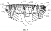
- the inner surface of the end of the main housing 210 is provided with a step portion 211 (as shown in FIG. 3 ) facing the first through holes 251, the sealing gasket 250 is attached to the inner surface of the end of the main housing 210, and each the flange 252 is embedded in the step portion 211.
- the sealing gasket 250 is elastically compressed to the inner surface of the end part of the main housing 210, with its flange 252 being embedded in the step portion 211, and its body part being closely attached to the inner surface of the end part of the main housing 210.
- the flange 252 can prevent water vapor from entering into the main housing 210 from the first through holes 251, and the body part of the sealing gasket 250 can prevent water vapor from entering into the main housing 210 from a gap between the sealing gasket 250 and the inner surface of the end of the main housing 210.
- the electrode assembly 220 includes an elongated first sub-electrode 2211, and the elongated first sub-electrode 2211 is arranged at the end of the main housing 210 and closing to a middle area of the main housing.
- a first fixing post T1 is protruded from an inner surface of the first sub-electrode 2211, and the first fixing post T1 of the first sub-electrode 2211 is inserted into the main housing 210 for fixing.
- an outer surface of the main housing 210 is defined with a first mounting groove T2 and a second through hole T3 is defined in a bottom of the first mounting groove T2, the insulating substrate 240 is defined with a third through hole T4 facing the second through hole T3, and the circuit board 230 is defined with a fourth through hole T5 facing the second through hole T3.
- the first sub-electrode 2211 is embedded in the first mounting groove T2, and the first fixing post T1 passes through the second through hole T3 and the third through hole T4 in sequence to be connected with a first fastener S1 inserted from the fourth through hole T5.
- the first mounting groove T2 may provide an accommodating and limiting space for a part of the first sub-electrode 2211 located outside the main housing 210, and the first sub-electrode 2211 partially protrudes outside the first mounting groove T2 to contact the skin.
- the second through hole T3 and the third through hole T4 provide a space for the first fixing post T1 of the first sub-electrode 2211 to pass through, and the fourth through hole T5 provides a space for the first fastener S1 to pass through.
- the first fixing post T1 is a stud, and the first fastener S1 is threadedly connected with the first fixing post T1.
- the sealing gasket 250 is defined with a fifth through hole T6 facing the second through hole T3 and the third through hole T4, and the first fixing post T1 further passes through the fifth through hole T6.
- an annular flange 252 is provided at an edge of a surface of the fifth through hole T6 facing away from the insulating substrate 240 to seal the first fixing post T1.
- there may be a plurality of first fixing posts T1 and the plurality of first fixing posts T1 are distributed in the length direction of the first sub-electrode 2211 at intervals to cooperate with a corresponding first fastener S1 to fix different parts of the first sub-electrode 2211.
- the first fastener S1 cooperates with the first fixing post T1 to fix the first sub-electrode 2211 at the end of the main housing 210, and fix the circuit board 230, the insulating substrate 240, and the sealing gasket 250 at an inner surface of the end of the main housing 210.
- the electrode assembly 220 further includes an elongated second sub-electrode 2212.
- the elongated second sub-electrode 2212 is arranged at the edge of the end of the main housing 210 and partially extends to the side of the main housing 210.
- a second fixing post 2212T is protruded from an inner surface of the second sub-electrode 2212 and obliquely arranged relative to the end of the main housing 210, and the second fixing post 2212T of the second sub-electrode 2212 is inserted into the main housing 210 for fixing.
- the outer surface of the main housing 210 is defined with a second mounting groove T12 and a sixth through hole T7 is defined in a bottom of the second mounting groove T12, an edge of the circuit board 230 is defined with a first avoidance groove 230C, and the edge of the insulating substrate 240 is defined with a second avoidance groove 240C.
- the second sub-electrode 2212 is embedded in the second mounting groove T12, and the second fixing post 2212T passes through the sixth through hole T7 to be connected with a second fastener S2 provided in the first avoidance groove 230C and the second avoidance groove 240C.
- the second mounting groove T12 may provide an accommodating and limiting space for a part of the second sub-electrode 2212 located outside the main housing 210, and the second sub-electrode 2212 partially protrudes outside the second mounting groove T12 to contact the skin.
- the sixth through hole T7 provides a space for the second fixing post 2212T of the second sub-electrode 2212 to pass through, and the second avoidance groove 240C and the first avoidance groove 230C provide an avoidance space for the second fixing post 2212T.
- the second fastener S2 is connected with the second fixing post 2212T and partially located in the first avoidance groove 230C.
- the second fixing post 2212T is a stud, and the second fastener S2 is threadedly connected with the second fixing post 2212T.
- the sealing gasket 250 is defined with an avoidance groove 250C facing the second avoidance groove 240C and the first avoidance groove 230C, and the second fixing post 2212T is partially arranged in the avoidance groove 250C for avoidance.
- the main housing 210 includes a cover plate 210A and a side plate 210B which are connected with each other, the side plate 210B is connected between the performing part 200 and the cover plate 210A, and the electrode assembly 220, the circuit board 230, and the insulating substrate 240 are arranged in a space surrounded by the cover plate 210A and the side plate 210B.
- the performing part 200 of the beauty instrument further includes an annular sealing ring M, and the sealing ring M is sealed between the cover plate 210A and the side plate 210B.
- the sealing ring M includes:
- An end face of the cover plate 210A facing the side plate 210B is defined with a circle of concave part 210R, and an end face of the side plate 210B facing the cover plate 210A is formed with a convex rib 210Q.
- the body part M1 and the second flange M3 are arranged in the concave part 210R, and an inner ring face of the body part M1 is abutted against the convex rib 210Q, and the cover plate 210A presses the first flange M2 against the end face of the side plate 210B.
- the body part M1 has an annular structure
- the second flange M3 is located on the outer ring surface of the body part M1
- the first flange M2 is located on the end face of the body part M1 and faced the side plate 210B.
- the sealing ring M is compressed between the cover plate 210A and the side plate 210B, and an end of the body part M1 facing away from the first flange M2 is pressed against the outer side of the rib 210Q by the inner side wall of the cover plate 210A, the second flange M3 is pressed against the end of the side plate 210B by the end of the cover plate 210A, and the first flange M2 is pressed against the end of the side plate 210B by the body part M1 to form close fit with the end of the side plate 210B.
- the sealing ring M, the rib 210Q, and the end of the cover plate 210A cooperate with each other, so that a large sealing contact surface can be formed on a joint surface of the cover plate 210A and the side plate 210B, improving waterproof sealing effect of the joint surface.
- the performing part 200 includes a fixing frame 260, and the fixing frame 260 is arranged at a side of the circuit board 230 facing away from the electrode assembly 220.
- the fixing frame 260 is fixed to the inner surface of the end of the main housing 210 and presses the circuit board 230, the insulating substrate 240, and the sealing gasket 250 in a stack against the inner surface of the end of the main housing 210.
- the performing part 200 includes a third fastener S3, a plurality of third fixing posts 260T are protruded on an edge of the fixing frame 260 and abutted against the circuit board 230, an end of the third fastener S3 penetrate through the third fixing post 260T, and the other end is connected with the inner surface of the end of the main housing 210.
- the edge of the circuit board 230 is defined with a third avoidance groove 230D corresponding to the third fastener S3, and/or the edge of the insulating substrate 240 is defined with a fourth avoidance groove 240D corresponding to the third fastener S3, and/or an edge of the sealing gasket 250 is defined with a fifth avoidance groove 250D corresponding to the third fastener S3.
- the third fastener S3 passes through the third fixing post 260T and is connected with the inner surface of the end of the main housing 210, the third fastener S3 is located in the corresponding third avoidance groove 230D and/or fourth avoidance groove 240D and/or fifth avoidance groove 250D.
- the circuit board 230, the insulating substrate 240, and the sealing gasket 250 can be tightly fixed in the main housing 210 by the third fixing post 260T abutting against the edge of the circuit board 230.
- a fourth fixing post 210T is protruded on the inner surface of the end of the main housing 210, and the third fastener S3 is connected with the fourth fixing post 210T.
- the fourth fixing post 210T is a stud
- the third fastener S3 is threadedly connected with the fourth fixing post 210T.
- the fourth fixing post 210T is abutted against the edge of the fixing frame 260, for example, the fourth fixing post 210T is abutted against the third fixing post 260T of the fixing frame 260.
- the assembled third fixing post 260T is abutted against both the third fixing post 260T and the edge of the circuit board 230, that is, by setting a protruding length of the fourth fixing post 210T, the end of the fourth fixing post 210T can be flush with a surface of the circuit board 230 abutted against the fixing frame 260, so that an internal space of the beauty instrument can be fully utilized.
- the fixing frame 260 is formed as a recessed groove body facing away from the circuit board 230, and the edge of the groove body is abutted against the edge of the circuit board 230.
- An installation space 260Q for accommodating electrical components or wires is formed between a bottom of the groove body and the circuit board 230.
- the circuit board 230 is provided with a protrusion 233 protruding towards the fixing frame 260, the fixing frame 260 is defined with an avoidance hole 261 facing the protrusion 233, and the protrusion 233 is at least partially embedded in the avoidance hole 261.
- the circuit board 230 includes a plurality of protrusions 233, and the fixing frame 260 is correspondingly defined with a plurality of avoidance holes 261 facing the protrusions 233.
- a side of the fixing frame 260 facing away from the cover plate 210A is fixed to the side plate 210B.
- a fifth fixing post 262 is protruded on a side of the fixing frame 260 facing away from the cover plate 210A, and a side of the cover plate 210A facing the fixing frame 260 is defined with a counterbore 210M.
- the fifth fixing post 262 is embedded in the counterbore 210M and is fixed in the counterbore 210M by a fastener (not shown) penetrating from a side of side plate 210B facing away from the fixing frame 260.
- the fixing frame 260, the insulating substrate 240, and the sealing gasket 250 can be fixed to the inner surface of the end of the main housing 210, that is, fixed to the cover plate 210A, by the third fastener S3 being loaded from the edge of the fixing frame 260.
- the fixing frame 260 By inserting another fastener from the side of the side plate 210B facing away from the fixing frame 260 through the counterbore 210M so as to be connected with the fifth fixing post 262 of the fixing frame 260, the fixing frame 260 can be fixed to the side plate 210B, and the sealing ring M can also be compressed, thus enhancing clamping effect of the side plate 210B and the cover plate 210A.
- a side of the side plate 210B facing the fixing frame 260 is provided with a plurality of ribs 210C, the fixing frame 260 is abutted against the ribs 210C, and the ribs 210C can strengthen and limit the fixing frame 260, thus improving structural strength of the performing part 200.
- the beauty instrument includes:
- the elongated first electrodes 221 at the two sides are large-area electrodes that act on the skin to discharge, and the dot electrodes 222 between the elongated first electrodes 221 uniformly discharge to the skin on an area between the first electrodes 221, so that user is prevented from obviously feeling the electrode provision area on the care head, discharge uniformity is improved, a care area of the electrodes of the beauty instrument is increased, and care experience and efficiency are also improved. Further, different electrodes can act on the skin in different areas, thereby further expanding application scenes and meeting care needs of different skin areas.
- the first electrodes 221 are parallel to each other. That is, extending directions of the first electrodes 221 are the same.
- the beauty instrument moves along the skin surface, the elongated first electrodes 221 at the two sides are in contact with the skin at the same time, thus forming a loop and generating a current at a contact site with the skin, for example, a micro current or radio frequency current, to perform skin care.
- the first electrode 221 is not limited to be of a regular strip shape, and for example, the first electrode 221 can also be a wavy, zigzag, or multi-segment connected electrode.
- the first electrodes 221 include a first sub-electrode 2211 and a second sub-electrode 2212, and the first sub-electrode 2211 and the second sub-electrode 2212 have opposite polarities and form an electrode pair.
- At least part of the dot electrodes 222 are arranged between the first sub-electrode 2211 and the second sub-electrode 2212 in an array, thus filling a blank area between the first sub-electrode 2211 and the second sub-electrode 2212, thus performing care for a target skin area between the first sub-electrode 2211 and the second sub-electrode 2212, expanding a discharge area of the beauty instrument and improving care efficiency.
- the first sub-electrode 2211 is disposed at the end of the main housing 210 and closing to the middle area of the main housing
- the second sub-electrode 2212 is arranged at an edge of the end of the main housing 210
- the second sub-electrode 2212 at least partially extends to the side of the main housing 210.
- the first sub-electrode 2211 and the dot electrodes 222 can serve to perform skin care on a large flat area, for example, by generating a micro current acting, to achieve skin resurfacing effect.
- the second sub-electrode 2212 can serve to perform care for an uneven skin surface.
- the second sub-electrode 2212 can be in contact with an edge of the nose to discharge to skin around the nose.
- the first electrodes 221 include two second sub-electrodes 2212, each second sub-electrode 2212 is located at one side edge of two side edges of the main housing 210, the first sub-electrode 2211 is arranged between the two second sub-electrodes 2212, and each of the two second sub-electrodes 2212 and the first sub-electrode 2211 have opposite polarities and form an electrode pair.
- first sub-electrode 2211 and a corresponding second sub-electrode 2212 at the two sides are in contact with the skin at the same time, they can form a loop and thus discharge to the skin.
- the second sub-electrodes 2212 at the two sides can perform care for skin in different areas, thus expanding application scenarios.
- dot electrodes 222 in an array are arranged between each of the second sub-electrodes 2212 and the first sub-electrode 2211.
- an area between the second sub-electrode 2212 on each side and the first sub-electrode 2211 at the middle can be filled with the dot electrodes 222 to discharge a target area between each of the second sub-electrodes 2212 and the first sub-electrode 2211.
- the electrode assembly 220 further includes a second electrode 223 disposed between the two second sub-electrodes 2212, and the second electrode 223 includes a first arc-shaped electrode 2231 and a second arc-shaped electrode 2232, which have opposite polarities and form an electrode pair.
- the first arc-shaped electrode 2231 and the second arc-shaped electrode 2232 are in contact with the skin at the same time, they can form a loop and thus discharge to the skin.
- the first arc-shaped electrode 2231 is arranged at the edge of the end of the main housing 210, and the first arc-shaped electrode 2231 extends to the side of the main housing 210. In this way, the first arc-shaped electrode 2231 of the second electrode 223 is located at the edge of the end of the main housing 210, and can cooperate with the second arc-shaped electrode 2232 to be in contact with an uneven skin surface to discharge.
- the two second sub-electrodes 2212 and the second electrode 223 surround the dot electrodes 222. Therefore, a blank area among the second sub-electrode 2212, the first arc-shaped electrode 2231, and the second arc-shaped electrode 2232 (that is, an area without electrodes) can be filled by the dot electrodes 222, to allow the dot electrodes 222 to discharge to the skin, thus increasing care area.
- dot electrodes 222 are disposed between the edge of the end of the main housing 210 and at least one end of the first sub-electrode 2211 in a longitudinal direction. In this way, the blank area on a surface of the main housing 210 can be further reduced, thus increasing an effective care area of the beauty instrument.
Landscapes
- Health & Medical Sciences (AREA)
- Life Sciences & Earth Sciences (AREA)
- Public Health (AREA)
- Veterinary Medicine (AREA)
- Radiology & Medical Imaging (AREA)
- Biomedical Technology (AREA)
- Animal Behavior & Ethology (AREA)
- General Health & Medical Sciences (AREA)
- Engineering & Computer Science (AREA)
- Nuclear Medicine, Radiotherapy & Molecular Imaging (AREA)
- Oral & Maxillofacial Surgery (AREA)
- Plastic & Reconstructive Surgery (AREA)
- Biophysics (AREA)
- Heart & Thoracic Surgery (AREA)
- Electrotherapy Devices (AREA)
- Thermotherapy And Cooling Therapy Devices (AREA)
Applications Claiming Priority (2)
| Application Number | Priority Date | Filing Date | Title |
|---|---|---|---|
| CN202321025281.7U CN219783540U (zh) | 2023-04-28 | 2023-04-28 | 美容仪 |
| PCT/CN2024/072064 WO2024222057A1 (zh) | 2023-04-28 | 2024-01-12 | 美容仪 |
Publications (4)
| Publication Number | Publication Date |
|---|---|
| EP4477256A1 true EP4477256A1 (de) | 2024-12-18 |
| EP4477256A4 EP4477256A4 (de) | 2025-07-09 |
| EP4477256C0 EP4477256C0 (de) | 2025-10-29 |
| EP4477256B1 EP4477256B1 (de) | 2025-10-29 |
Family
ID=88179993
Family Applications (1)
| Application Number | Title | Priority Date | Filing Date |
|---|---|---|---|
| EP24758129.1A Active EP4477256B1 (de) | 2023-04-28 | 2024-01-12 | Schönheitspflegeinstrument |
Country Status (10)
| Country | Link |
|---|---|
| US (1) | US12527953B2 (de) |
| EP (1) | EP4477256B1 (de) |
| JP (1) | JP7839302B2 (de) |
| KR (1) | KR20240161101A (de) |
| CN (1) | CN219783540U (de) |
| CA (1) | CA3249666A1 (de) |
| ES (1) | ES3054970T3 (de) |
| MX (1) | MX2024014407A (de) |
| TW (1) | TWM654237U (de) |
| WO (1) | WO2024222057A1 (de) |
Families Citing this family (3)
| Publication number | Priority date | Publication date | Assignee | Title |
|---|---|---|---|---|
| USD1085532S1 (en) * | 2022-03-29 | 2025-07-22 | Shenzhen Ulike Smart Electronics Co. Ltd | Operating head of beauty device |
| CN219783540U (zh) | 2023-04-28 | 2023-10-03 | 深圳由莱智能电子有限公司 | 美容仪 |
| USD1100227S1 (en) * | 2024-03-27 | 2025-10-28 | Shenzhen Ulike Smart Electronics Co., Ltd. | Electrode head of the skin treatment device |
Family Cites Families (41)
| Publication number | Priority date | Publication date | Assignee | Title |
|---|---|---|---|---|
| US6119038A (en) * | 1998-11-20 | 2000-09-12 | Proventure, Llc | Handheld skin treatment system and method |
| US9827437B2 (en) * | 2006-01-17 | 2017-11-28 | Endymed Medical Ltd | Skin treatment devices and methods |
| WO2010140582A1 (ja) | 2009-06-03 | 2010-12-09 | 九州日立マクセル株式会社 | 美容機器 |
| KR101065611B1 (ko) * | 2010-12-01 | 2011-09-19 | 주식회사 은성글로벌상사 | 고주파 피부 미용 장치 |
| CN202207398U (zh) * | 2011-07-22 | 2012-05-02 | 李娜 | 一种多触点射频美容仪 |
| WO2013021380A1 (en) * | 2011-08-09 | 2013-02-14 | Syneron Beauty Ltd. | A method and apparatus for cosmetic skin care |
| US8954155B2 (en) * | 2011-09-19 | 2015-02-10 | Biotalk Technologies Inc | Apparatus and method for rejuvenating skin |
| KR101297791B1 (ko) * | 2013-03-22 | 2013-08-19 | 이기세 | 피부미용장치의 팁 구조 |
| US20160121108A1 (en) * | 2013-11-11 | 2016-05-05 | Artistic&Co.Co.,Ltd. | Beauty instrument |
| CN203971193U (zh) | 2014-06-06 | 2014-12-03 | 深圳市景瑞科技有限公司 | 点阵射频美容仪 |
| JP6264693B2 (ja) | 2014-07-31 | 2018-01-24 | パナソニックIpマネジメント株式会社 | 美容装置 |
| FR3045289B1 (fr) | 2015-12-17 | 2021-09-03 | Oreal | Dispositif de traitement des matieres keratiniques humaines, notamment a l'aide d'un courant electrique |
| KR101642248B1 (ko) | 2016-03-03 | 2016-07-22 | (주)아모레퍼시픽 | 피부 미용기기 |
| KR102628092B1 (ko) | 2016-11-07 | 2024-01-23 | 엘지전자 주식회사 | 피부 케어 기기 |
| KR101859195B1 (ko) * | 2017-10-13 | 2018-05-17 | 강선영 | 석션 기능을 갖는 ret방식 고주파 마사지기 |
| JP2019088373A (ja) | 2017-11-13 | 2019-06-13 | 株式会社 Artistic&Co. | 美容器 |
| CN209108014U (zh) * | 2018-04-28 | 2019-07-16 | 广州伊绅电子科技有限公司 | 一种负压美容仪探头 |
| JP2021023430A (ja) | 2019-07-31 | 2021-02-22 | ヤーマン株式会社 | 美容機器 |
| JP7377649B2 (ja) | 2019-08-09 | 2023-11-10 | マクセル株式会社 | 美容器具 |
| JP7387397B2 (ja) | 2019-11-13 | 2023-11-28 | 株式会社 Mtg | 美容機器 |
| JP3225776U (ja) * | 2020-01-22 | 2020-04-02 | Tbcグループ株式会社 | 電気筋肉刺激機器 |
| US20220015987A1 (en) * | 2020-07-17 | 2022-01-20 | Filip Sedic | Treatment Devices and Methods of Use |
| JP7454799B2 (ja) | 2020-10-16 | 2024-03-25 | 株式会社ジェイ クラフト | マッサージ器 |
| CN215384554U (zh) | 2021-08-11 | 2022-01-04 | 游振德 | 一种多功能美容仪 |
| CN113842556A (zh) | 2021-09-07 | 2021-12-28 | 深圳市千誉科技有限公司 | 美容仪 |
| CN113813507A (zh) | 2021-10-29 | 2021-12-21 | 广东时光颜究所美容科技有限公司 | 美容仪及其输出控制方法 |
| CN217526118U (zh) | 2022-03-15 | 2022-10-04 | 深圳市宗匠科技有限公司 | 电极头和美容仪 |
| CN218010647U (zh) | 2022-03-15 | 2022-12-13 | 深圳市宗匠科技有限公司 | 射频美容仪 |
| CN217773000U (zh) | 2022-03-15 | 2022-11-11 | 深圳市宗匠科技有限公司 | 射频美容仪 |
| CN217526101U (zh) | 2022-03-15 | 2022-10-04 | 深圳市宗匠科技有限公司 | 电极头和美容仪 |
| CN218010648U (zh) | 2022-04-26 | 2022-12-13 | 深圳市拓大医疗科技有限公司 | 一种射频美容仪 |
| CN218572657U (zh) | 2022-06-21 | 2023-03-07 | 厦门建霖健康家居股份有限公司 | 一种美容按摩仪 |
| CN218774178U (zh) | 2022-06-28 | 2023-03-31 | 广东花至美容科技有限公司 | 一种美容仪护理头 |
| CN115282487B (zh) | 2022-08-17 | 2024-09-13 | 云南贝泰妮生物科技集团股份有限公司 | 一种眼面两用的折面式射频美容仪 |
| CN115282486B (zh) * | 2022-08-17 | 2024-07-02 | 云南贝泰妮生物科技集团股份有限公司 | 一种全脸覆盖式的家用射频美容面罩 |
| JP7817272B2 (ja) * | 2022-09-30 | 2026-02-18 | 深▲せん▼由莱智能電子有限公司 | 携帯型美容機器 |
| CN116271518A (zh) | 2022-09-30 | 2023-06-23 | 深圳由莱智能电子有限公司 | 便携式美容仪 |
| CN115999070A (zh) * | 2022-12-29 | 2023-04-25 | 广东花至美容科技有限公司 | 用于美容仪的电极头及其美容仪 |
| CN219783541U (zh) * | 2023-04-28 | 2023-10-03 | 深圳由莱智能电子有限公司 | 美容仪 |
| CN219783539U (zh) * | 2023-04-28 | 2023-10-03 | 深圳由莱智能电子有限公司 | 美容仪 |
| CN219783540U (zh) * | 2023-04-28 | 2023-10-03 | 深圳由莱智能电子有限公司 | 美容仪 |
-
2023
- 2023-04-28 CN CN202321025281.7U patent/CN219783540U/zh active Active
-
2024
- 2024-01-12 EP EP24758129.1A patent/EP4477256B1/de active Active
- 2024-01-12 KR KR1020247028526A patent/KR20240161101A/ko active Pending
- 2024-01-12 JP JP2024563374A patent/JP7839302B2/ja active Active
- 2024-01-12 ES ES24758129T patent/ES3054970T3/es active Active
- 2024-01-12 CA CA3249666A patent/CA3249666A1/en active Pending
- 2024-01-12 WO PCT/CN2024/072064 patent/WO2024222057A1/zh not_active Ceased
- 2024-01-30 TW TW113201067U patent/TWM654237U/zh unknown
- 2024-08-28 US US18/818,555 patent/US12527953B2/en active Active
- 2024-11-21 MX MX2024014407A patent/MX2024014407A/es unknown
Also Published As
| Publication number | Publication date |
|---|---|
| KR20240161101A (ko) | 2024-11-12 |
| JP2025516482A (ja) | 2025-05-30 |
| CA3249666A1 (en) | 2025-06-17 |
| CN219783540U (zh) | 2023-10-03 |
| EP4477256C0 (de) | 2025-10-29 |
| EP4477256A4 (de) | 2025-07-09 |
| WO2024222057A1 (zh) | 2024-10-31 |
| US20240416116A1 (en) | 2024-12-19 |
| JP7839302B2 (ja) | 2026-04-01 |
| TWM654237U (zh) | 2024-04-11 |
| EP4477256B1 (de) | 2025-10-29 |
| MX2024014407A (es) | 2025-01-09 |
| ES3054970T3 (en) | 2026-02-09 |
| US12527953B2 (en) | 2026-01-20 |
Similar Documents
| Publication | Publication Date | Title |
|---|---|---|
| EP4477256A1 (de) | Schönheitspflegeinstrument | |
| KR200496636Y1 (ko) | 미용 장치의 두부 및 미용 장치 | |
| KR20210158830A (ko) | 피부 관리 기기 | |
| JP5945061B2 (ja) | バッテリー内蔵型携帯用高周波治療器 | |
| CN117794613A (zh) | 便携式美容仪 | |
| US12168125B2 (en) | Beauty equipment | |
| CN219783539U (zh) | 美容仪 | |
| CN219783541U (zh) | 美容仪 | |
| JP2024541779A (ja) | 携帯型美容機器及びその充電台 | |
| CN215689734U (zh) | 按摩仪 | |
| CN211326661U (zh) | 用于颈椎按摩仪的按摩组件和颈椎按摩仪 | |
| CN214415203U (zh) | 颈部按摩仪 | |
| CN118059398A (zh) | 超声波美容仪 | |
| CN214208635U (zh) | 一种按摩头及颈部按摩仪 | |
| EP3984587A1 (de) | Nadelanordnung, hautstimulator damit und herstellungsverfahren dafür | |
| CN215275420U (zh) | 射频头及射频仪 | |
| CN114681291A (zh) | 按摩仪 | |
| CN206950464U (zh) | 结合了光源、热源的美容用仪器 | |
| CN221431933U (zh) | 射频美容设备 | |
| CN220046866U (zh) | 电极头和美容仪 | |
| CN221451531U (zh) | 一种能量盒以及美容仪 | |
| CN222738090U (zh) | 美容按摩仪 | |
| CN118161766A (zh) | 超声波美容仪 | |
| CN219251414U (zh) | 一种按摩腰带 | |
| CN220755254U (zh) | 美容仪 |
Legal Events
| Date | Code | Title | Description |
|---|---|---|---|
| STAA | Information on the status of an ep patent application or granted ep patent |
Free format text: STATUS: UNKNOWN |
|
| STAA | Information on the status of an ep patent application or granted ep patent |
Free format text: STATUS: THE INTERNATIONAL PUBLICATION HAS BEEN MADE |
|
| PUAI | Public reference made under article 153(3) epc to a published international application that has entered the european phase |
Free format text: ORIGINAL CODE: 0009012 |
|
| STAA | Information on the status of an ep patent application or granted ep patent |
Free format text: STATUS: REQUEST FOR EXAMINATION WAS MADE |
|
| 17P | Request for examination filed |
Effective date: 20240827 |
|
| AK | Designated contracting states |
Kind code of ref document: A1 Designated state(s): AL AT BE BG CH CY CZ DE DK EE ES FI FR GB GR HR HU IE IS IT LI LT LU LV MC ME MK MT NL NO PL PT RO RS SE SI SK SM TR |
|
| A4 | Supplementary search report drawn up and despatched |
Effective date: 20250605 |
|
| RIC1 | Information provided on ipc code assigned before grant |
Ipc: A61N 1/32 20060101ALI20250602BHEP Ipc: A61N 1/18 20060101ALI20250602BHEP Ipc: A61N 1/04 20060101ALI20250602BHEP Ipc: A45D 44/22 20060101ALI20250602BHEP Ipc: A61N 1/36 20060101AFI20250602BHEP |
|
| GRAP | Despatch of communication of intention to grant a patent |
Free format text: ORIGINAL CODE: EPIDOSNIGR1 |
|
| STAA | Information on the status of an ep patent application or granted ep patent |
Free format text: STATUS: GRANT OF PATENT IS INTENDED |
|
| RIC1 | Information provided on ipc code assigned before grant |
Ipc: A61N 1/36 20060101AFI20250717BHEP Ipc: A45D 44/22 20060101ALI20250717BHEP Ipc: A61N 1/04 20060101ALI20250717BHEP Ipc: A61N 1/18 20060101ALI20250717BHEP Ipc: A61N 1/32 20060101ALI20250717BHEP |
|
| DAV | Request for validation of the european patent (deleted) | ||
| DAX | Request for extension of the european patent (deleted) | ||
| INTG | Intention to grant announced |
Effective date: 20250820 |
|
| GRAS | Grant fee paid |
Free format text: ORIGINAL CODE: EPIDOSNIGR3 |
|
| GRAA | (expected) grant |
Free format text: ORIGINAL CODE: 0009210 |
|
| STAA | Information on the status of an ep patent application or granted ep patent |
Free format text: STATUS: THE PATENT HAS BEEN GRANTED |
|
| AK | Designated contracting states |
Kind code of ref document: B1 Designated state(s): AL AT BE BG CH CY CZ DE DK EE ES FI FR GB GR HR HU IE IS IT LI LT LU LV MC ME MK MT NL NO PL PT RO RS SE SI SK SM TR |
|
| REG | Reference to a national code |
Ref country code: CH Ref legal event code: F10 Free format text: ST27 STATUS EVENT CODE: U-0-0-F10-F00 (AS PROVIDED BY THE NATIONAL OFFICE) Effective date: 20251029 Ref country code: GB Ref legal event code: FG4D |
|
| REG | Reference to a national code |
Ref country code: IE Ref legal event code: FG4D |
|
| REG | Reference to a national code |
Ref country code: DE Ref legal event code: R096 Ref document number: 602024001102 Country of ref document: DE |
|
| U01 | Request for unitary effect filed |
Effective date: 20251117 |
|
| U07 | Unitary effect registered |
Designated state(s): AT BE BG DE DK EE FI FR IT LT LU LV MT NL PT RO SE SI Effective date: 20251121 |
|
| REG | Reference to a national code |
Ref country code: ES Ref legal event code: FG2A Ref document number: 3054970 Country of ref document: ES Kind code of ref document: T3 Effective date: 20260209 |
|
| U20 | Renewal fee for the european patent with unitary effect paid |
Year of fee payment: 3 Effective date: 20260107 |
|
| PGFP | Annual fee paid to national office [announced via postgrant information from national office to epo] |
Ref country code: ES Payment date: 20260226 Year of fee payment: 3 |
|
| PG25 | Lapsed in a contracting state [announced via postgrant information from national office to epo] |
Ref country code: NO Free format text: LAPSE BECAUSE OF FAILURE TO SUBMIT A TRANSLATION OF THE DESCRIPTION OR TO PAY THE FEE WITHIN THE PRESCRIBED TIME-LIMIT Effective date: 20260129 |
|
| PG25 | Lapsed in a contracting state [announced via postgrant information from national office to epo] |
Ref country code: HR Free format text: LAPSE BECAUSE OF FAILURE TO SUBMIT A TRANSLATION OF THE DESCRIPTION OR TO PAY THE FEE WITHIN THE PRESCRIBED TIME-LIMIT Effective date: 20251029 |
|
| PG25 | Lapsed in a contracting state [announced via postgrant information from national office to epo] |
Ref country code: RS Free format text: LAPSE BECAUSE OF FAILURE TO SUBMIT A TRANSLATION OF THE DESCRIPTION OR TO PAY THE FEE WITHIN THE PRESCRIBED TIME-LIMIT Effective date: 20260129 |
|
| PG25 | Lapsed in a contracting state [announced via postgrant information from national office to epo] |
Ref country code: IS Free format text: LAPSE BECAUSE OF FAILURE TO SUBMIT A TRANSLATION OF THE DESCRIPTION OR TO PAY THE FEE WITHIN THE PRESCRIBED TIME-LIMIT Effective date: 20260228 |