EP4477182A2 - Kipphebelanordnung für kopffixierungsvorrichtung - Google Patents
Kipphebelanordnung für kopffixierungsvorrichtung Download PDFInfo
- Publication number
- EP4477182A2 EP4477182A2 EP24210801.7A EP24210801A EP4477182A2 EP 4477182 A2 EP4477182 A2 EP 4477182A2 EP 24210801 A EP24210801 A EP 24210801A EP 4477182 A2 EP4477182 A2 EP 4477182A2
- Authority
- EP
- European Patent Office
- Prior art keywords
- contact
- rocker arm
- arm assembly
- head
- angle
- Prior art date
- Legal status (The legal status is an assumption and is not a legal conclusion. Google has not performed a legal analysis and makes no representation as to the accuracy of the status listed.)
- Granted
Links
Images


Classifications
-
- A—HUMAN NECESSITIES
- A61—MEDICAL OR VETERINARY SCIENCE; HYGIENE
- A61B—DIAGNOSIS; SURGERY; IDENTIFICATION
- A61B90/00—Instruments, implements or accessories specially adapted for surgery or diagnosis and not covered by any of the groups A61B1/00 - A61B50/00, e.g. for luxation treatment or for protecting wound edges
- A61B90/10—Instruments, implements or accessories specially adapted for surgery or diagnosis and not covered by any of the groups A61B1/00 - A61B50/00, e.g. for luxation treatment or for protecting wound edges for stereotaxic surgery, e.g. frame-based stereotaxis
- A61B90/14—Fixators for body parts, e.g. skull clamps; Constructional details of fixators, e.g. pins
-
- A—HUMAN NECESSITIES
- A61—MEDICAL OR VETERINARY SCIENCE; HYGIENE
- A61F—FILTERS IMPLANTABLE INTO BLOOD VESSELS; PROSTHESES; DEVICES PROVIDING PATENCY TO, OR PREVENTING COLLAPSING OF, TUBULAR STRUCTURES OF THE BODY, e.g. STENTS; ORTHOPAEDIC, NURSING OR CONTRACEPTIVE DEVICES; FOMENTATION; TREATMENT OR PROTECTION OF EYES OR EARS; BANDAGES, DRESSINGS OR ABSORBENT PADS; FIRST-AID KITS
- A61F5/00—Orthopaedic methods or devices for non-surgical treatment of bones or joints; Nursing devices ; Anti-rape devices
- A61F5/37—Restraining devices for the body or for body parts; Restraining shirts
- A61F5/3707—Restraining devices for the body or for body parts; Restraining shirts for the head
-
- A—HUMAN NECESSITIES
- A61—MEDICAL OR VETERINARY SCIENCE; HYGIENE
- A61G—TRANSPORT, PERSONAL CONVEYANCES, OR ACCOMMODATION SPECIALLY ADAPTED FOR PATIENTS OR DISABLED PERSONS; OPERATING TABLES OR CHAIRS; CHAIRS FOR DENTISTRY; FUNERAL DEVICES
- A61G13/00—Operating tables; Auxiliary appliances therefor
- A61G13/10—Parts, details or accessories
- A61G13/12—Rests specially adapted therefor; Arrangements of patient-supporting surfaces
- A61G13/1205—Rests specially adapted therefor; Arrangements of patient-supporting surfaces for specific parts of the body
- A61G13/121—Head or neck
-
- A—HUMAN NECESSITIES
- A61—MEDICAL OR VETERINARY SCIENCE; HYGIENE
- A61B—DIAGNOSIS; SURGERY; IDENTIFICATION
- A61B17/00—Surgical instruments, devices or methods
- A61B17/16—Instruments for performing osteoclasis; Drills or chisels for bones; Trepans
- A61B17/17—Guides or aligning means for drills, mills, pins or wires
- A61B17/1739—Guides or aligning means for drills, mills, pins or wires specially adapted for particular parts of the body
-
- A—HUMAN NECESSITIES
- A61—MEDICAL OR VETERINARY SCIENCE; HYGIENE
- A61B—DIAGNOSIS; SURGERY; IDENTIFICATION
- A61B17/00—Surgical instruments, devices or methods
- A61B17/56—Surgical instruments or methods for treatment of bones or joints; Devices specially adapted therefor
- A61B17/58—Surgical instruments or methods for treatment of bones or joints; Devices specially adapted therefor for osteosynthesis, e.g. bone plates, screws or setting implements
- A61B17/68—Internal fixation devices, including fasteners and spinal fixators, even if a part thereof projects from the skin
- A61B17/84—Fasteners therefor or fasteners being internal fixation devices
- A61B17/846—Nails or pins, i.e. anchors without movable parts, holding by friction only, with or without structured surface
-
- A—HUMAN NECESSITIES
- A61—MEDICAL OR VETERINARY SCIENCE; HYGIENE
- A61B—DIAGNOSIS; SURGERY; IDENTIFICATION
- A61B17/00—Surgical instruments, devices or methods
- A61B17/56—Surgical instruments or methods for treatment of bones or joints; Devices specially adapted therefor
- A61B17/58—Surgical instruments or methods for treatment of bones or joints; Devices specially adapted therefor for osteosynthesis, e.g. bone plates, screws or setting implements
- A61B17/68—Internal fixation devices, including fasteners and spinal fixators, even if a part thereof projects from the skin
- A61B17/84—Fasteners therefor or fasteners being internal fixation devices
- A61B17/86—Pins or screws or threaded wires; nuts therefor
-
- A—HUMAN NECESSITIES
- A61—MEDICAL OR VETERINARY SCIENCE; HYGIENE
- A61B—DIAGNOSIS; SURGERY; IDENTIFICATION
- A61B90/00—Instruments, implements or accessories specially adapted for surgery or diagnosis and not covered by any of the groups A61B1/00 - A61B50/00, e.g. for luxation treatment or for protecting wound edges
- A61B90/10—Instruments, implements or accessories specially adapted for surgery or diagnosis and not covered by any of the groups A61B1/00 - A61B50/00, e.g. for luxation treatment or for protecting wound edges for stereotaxic surgery, e.g. frame-based stereotaxis
- A61B2090/103—Cranial plugs for access to brain
Definitions
- HFDs head stabilization devices
- HFDs head fixation devices
- HFDs are sometimes used during a variety of surgical and other medical procedures, for example during head or neck surgery or testing where it would be desirable to securely hold a patient's head in a certain position.
- HFDs can include various components that are configured to contact the head of the patient. Some such components include skull pins or pads that can be retained in a pin or pad holder assembly. Some devices and methods disclosed herein pertain to various pin or pad holder assemblies. While a variety of stabilization devices and components thereof have been made and used, it is believed that no one prior to the inventor(s) has made or used an invention as described herein.
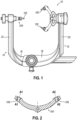
- FIG. 1 shows an exemplary HFD in the form of a skull clamp (10) that uses 3-point fixation.
- Skull clamp (10) comprises a pair of arms (12, 14) with each arm (12, 14) having a lateral portion (16, 18) and an upright portion (20, 22). Arms (12, 14) are adjustable laterally relative to each other so skull clamp (10) accommodates various patient head sizes.
- Skull clamp (10) includes a rocker arm assembly (100) that holds two pins (102) on one side of skull clamp (10). In the illustrated version, rocker arm assembly (100) is connected with skull clamp (10) at an end of upright portion (20). Opposite rocker arm assembly (100) at an end of upright portion (22) is a single pin holder (104) holding a single pin (102).
- FIG. 2 shows an arm (106) of rocker arm assembly (100) in cross section.
- Arm (106) comprises a curved shaped in the illustrated version, and a pair of bores (108) within arm (106).
- bores (108) are configured to retain pins (102) at each respective end of the arm (106).
- Arm (106) further angles inward such that longitudinal axes (A1, A2) defined by bores (108) of arm (106) extend in a converging manner as shown.
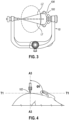
- FIG. 3 shows a stabilization arrangement with a head of a patient that is elliptically shaped using skull clamp (10).
- the contact angles defined by the pins and their interface with the patient's head are shown by diagonally extending lines (L1, L2) that form a triangular shape.
- the term "contact angle” as used herein should be understood to also include the penetration angle when the stabilization involves the pin or contact feature penetrating the bone as opposed to only contacting the bone without penetration.
- the term “contact angle” is understood to be inclusive of both the angle of contact and the angle of penetration depending on the configuration of the stabilization.
- arm (106) of a rocker arm assembly (100) is configured with a curved shape designed to work with an elliptically shaped head of a patient to provide for a desired contact angle.
- the position of all three pins form an isosceles triangle. This provides load distributing among all three pins and the pins are configured with contact angles of ninety or about ninety degrees. In other words, the pins contact and may be driven into the cranial bone at ninety or about ninety degrees or perpendicular or substantially perpendicular to the cranial bone.
- FIG. 4 shows a stabilization arrangement where skull pin (102) defines a longitudinal axis (A3), and skull pin (102) is positioned in contact with an elliptically shaped portion of the head of a patient.
- a tangent line (T1) is shown at the point of contact where skull pin (102) contacts the head.
- the contact angle ( ⁇ 1) defined as the angle between longitudinal axis (A3) of skull pin (102) and tangent line (T1), is shown as ninety or about ninety degrees.
- skull pin (102) makes a rigid and stable connection with the head.
- planar region of the cranial bone can be planar, generally planar, or substantially planar over some distance of the bone structure.
- planar region should be understood to encompass not only a planar region, but also a generally planar region, substantially planar region, a quasi-planar region, and/or other variations of these terms as will be understood by those of ordinary skill in the art in view of the teachings herein.
- pinning in a planar region of the cranial bone can be the case in procedures in which the patient is positioned face down (prone position). For instance, in order to perform a surgery in the occipital region, in the posterior fossa, or at the cervical spine, in at least some instances the pins are placed in a planar region of temporal bone and parietal bone.
- FIG. 5 shows portions of rocker arm assembly (100) of FIGS. 1-3 used with a planar portion of cranial bone (30) of the head of the patient.
- the angle of contact is greater than ninety degrees. More specifically, the contact angles ( ⁇ 1, ⁇ 2) are defined as the angle between longitudinal axes (A4, A5) of respective skull pins (102) and tangent line (T2).
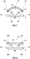
- FIG. 7 shows portions of rocker arm assembly (100) of FIG. 5 without pins (102), and again being used with a planar portion of cranial bone (30) of the head of the patient.
- the angle of contact is greater than ninety degrees. More specifically, the contact angles ( ⁇ 3, ⁇ 4) are defined as the angle between longitudinal axes (A6, A7) of respective bores (108) and tangent line (T2).
- contact angle can be defined based on the orientation of bores (108) or the orientation of pins (102).
- pins (102) are straight and bores (108) define concentric receptacles for receiving pins (102)
- the longitudinal axes defined by bores (108) and pins (102) will be the same.
- the contact angles will be the same whether defined by the orientation of bores (108) or the orientation of pins (102).
- bores (108) may be omitted where pins (102) may be formed with or as part of arm (106). In such an example, the contact angle will be defined based on the orientation of the pins (102).
- bores (108) and pins (102) can be shaped or configured such that they do not have the same or a common longitudinal axis, and thus would define different contact angles as defined herein. By way of example only, and not limitation, this could be the case where pins (102) are angled or curved instead of straight.
- other configurations for rocker arm assembly (100), with pins (102) and bores (108), where pins (102) and bores (108) have different longitudinal axes, and thus different contact angles as defined herein will be apparent to those of ordinary skill.
- the contact angle as defined by the contact features or pins is a key factor when considering the stability of a patient stabilization as it is those contact features or pins that contact the patient's head.
- FIG. 9 shows an exemplary HFD in the form of a skull clamp (50) that uses 3-point fixation.
- Skull clamp (50) comprises pair of arms (12, 14) with each arm (12, 14) having lateral portion (16, 18) and upright portion (20, 22). Arms (12, 14) are adjustable laterally relative to each other so skull clamp (50) accommodates various patient head sizes.
- Skull clamp (50) includes a rocker arm assembly (300) that holds two pins (302) on one side of skull clamp (50). In the illustrated version, rocker arm assembly (300) is connected with skull clamp (50) at end of upright portion (20). Opposite rocker arm assembly (300) at end of upright portion (22) is a single pin holder (304) holding a single pin (302).
- FIG. 6 shows portions of exemplary 2-pin rocker arm assembly (300) that is configured for use with skull clamp (50) like shown in FIG. 9 , but which also may be configured for use in place of rocker arm assembly (100) of skull clamp (10) as shown in FIGS. 1-3 , as well as other types of HFDs.
- 2-pin rocker arm assembly (300) is used with a planar portion of cranial bone (30) of the head of the patient.
- the angle of contact is ninety degrees or about ninety degrees. This is the case for both pins (302) configured to be used with the 2-pin rocker arm assembly (300). More specifically, the contact angles ( ⁇ 5, ⁇ 6) on each side of arm (306) are defined as the angle between longitudinal axes (A8, A9) of respective pins (302) and tangent line (T2).
- rocker arm assembly (300) provides for achieving a ninety-degree contact angle, or thereabouts, for each of the pins retained by rocker arm assembly (300) when stabilizing when pinning into a planar region of the skull of the patient's head.
- pins (302) are perpendicularly pinned into the planar region of cranial bone in this arrangement shown in FIG. 6 .
- rocker arm assembly (300) enables the surgeon or user to realize a perpendicular bone contact or penetration of pins (302) in rocker arm assembly (300) even though a planar region of cranial bone is pinned or used as a stabilizing location.
- FIG. 8 shows portions of rocker arm assembly (300) of FIG. 6 without pins (302).
- rocker arm assembly (300) with arm (306) and bores (308), is configured for use in pinning into a planar region of cranial bone.
- the angle of contact is ninety degrees or about ninety degrees. More specifically, the contact angles ( ⁇ 7, ⁇ 8) on each side of arm (306) are defined as the angle between longitudinal axes (A10, A11) of respective bores (308) and tangent line (T2).
- contact angle can be defined based on the orientation of bores (308) or the orientation of pins (302).
- pins (302) are straight and bores (308) define concentric receptacles for receiving pins (302)
- the longitudinal axes defined by bores (308) and pins (302) will be the same.
- the contact angles will be the same whether defined by the orientation of bores (308) or the orientation of pins (302).
- bores (308) may be omitted where pins (302) may be formed with, or as part of, arm (306).
- the contact angle will be defined based on the orientation of the pins (302).
- bores (308) and pins (302) can be shaped or configured such that they do not have the same or a common longitudinal axis, and thus would have different contact angles as defined herein. By way of example only, and not limitation, this could be the case where pins (302) are angled or curved instead of straight.
- other configurations for rocker arm assembly (300) with pins (302) and bores (308), where pins (302) and bores (308) have different longitudinal axes, and thus different contact angles as defined herein, will be apparent to those of ordinary skill in the art.
- the contact angle as defined by the contact features or pins is a key factor when considering the stability of a patient stabilization as it is those contact features or pins that contact the patient's head.
- arm (306) may be approximately 9 mm x 9 mm x 70 mm - 110 mm, with two perpendicular pin receptors or bores (308) at the ends of arm (306) at a distance of about 50 mm - 90 mm between each other.
- arm (306) is smaller, such that arm (306) is approximately 9 mm x 9 mm x 40 mm - 70 mm, with two perpendicular pin receptors or bores (308) at the ends of the arm at a distance of about 20 mm - 55 mm between each other.
- 2-pin rocker arm assembly (300) may be configured for use with pediatric patent's or patent's having smaller head size.
- respective pins (102, 302) define a longitudinal axis or centerline as shown in FIGS. 5 and 6 .
- the centerlines of each of the pair of pins intersect forming an angle, such as ⁇ 1 in FIG. 5 for rocker arm assembly (100).
- This angle defines an angle of the arc, and may also be referred to herein as the radius or degree of curvature of the arm.
- angle ⁇ 1 is forty degrees.
- the centerlines or longitudinal axes of pins (302) are parallel and thus do not intersect to define an angle.
- the centerlines or longitudinal axes of pins (302) are close to parallel, but not exactly parallel, they intersect to define an angle as mentioned above. In such cases where these axes are close but not exactly parallel, the angle defined is less than forty degrees.
- the angle represented by ⁇ 2 may be something that is equal to or greater than about zero degrees (as defined by ⁇ 2 in FIG. 6 ) and less than forty degrees. It should be noted that herein a zero-degree angle for ⁇ 2 is being defined as the case when the axes defined by pins (302) are parallel.
- a rocker arm assembly configured for pinning with a planar region of cranial bone can have a degree of curvature of the arm, defined by the angle formed by the longitudinal axes or centerlines of each of the pair of pins, that is greater than or equal to about zero degrees and less than forty degrees.
- a degree of curvature of the arm defined by the angle formed by the longitudinal axes or centerlines of each of the pair of pins, that is greater than or equal to about zero degrees and less than forty degrees.
- arm (306) of rocker arm assembly (300) has a straight, non-curved shape.
- arm (106) of rocker arm assembly (100) can have a slight curvature.
- arm (306) is straight, while in some other versions arm (306) may have a curvature, but to a lesser degree than the curvature of rocker arm assemblies that are designed for pinning elliptically shaped cranial bone. Still in some other examples this range for the angle may be between about zero degrees and about thirty degrees, or between about zero degrees and about 20 degrees, or between about zero degrees and about 10 degrees. In view of the teachings herein, other such ranges will be apparent to those of ordinary skill in in the art.
- respective bores (108, 308) define a longitudinal axis or centerline as shown in FIGS. 7 and 8 .
- the centerlines of each of the pair of bores (108, 308) intersect forming an angle, such as ⁇ 3 in FIG. 7 for rocker arm assembly (100).
- This angle defines an angle of the arc, and may also be referred to herein as the radius or degree of curvature of the arm (106).
- angle ⁇ 3 is forty degrees.
- the centerlines or longitudinal axes of bores (308) are parallel and thus do not intersect to define an angle.
- the centerlines or longitudinal axes of bores (308) are close to parallel, but not exactly parallel, they intersect to define an angle as mentioned above. In such cases where these axes are close but not exactly parallel, the angle defined is less than forty degrees.
- the angle represented by ⁇ 4 may be something that is equal to or greater than about zero degrees (as defined by ⁇ 4 in FIG. 8 ) and less than forty degrees. It should be noted that herein a zero-degree angle for ⁇ 4 is being defined as the case when the axes defined by bores (308) are parallel
- a rocker arm assembly configured for pinning with a planar region of cranial bone can have a degree of curvature of the arm, defined by the angle formed by the longitudinal axes or centerlines of each of the pair of bores, that is greater than or equal to about zero degrees and less than forty degrees.
- a degree of curvature of the arm defined by the angle formed by the longitudinal axes or centerlines of each of the pair of bores, that is greater than or equal to about zero degrees and less than forty degrees.
- arm (306) of rocker arm assembly (300) has a straight, non-curved shape.
- arm (106) of rocker arm assembly (100) can have a slight curvature.
- arm (306) is straight, while in some other versions arm (106) may have a curvature, but to a lesser degree than the curvature of rocker arm assemblies designed for pinning elliptically shaped cranial bone. Still in some other examples this range for the angle may be between about zero degrees and about thirty degrees, or between about zero degrees and about 20 degrees, or between about zero degrees and about 10 degrees. In view of the teachings herein, other such ranges will be apparent to those of ordinary skill in in the art.
- rocker arm assemblies like rocker arm assembly (100) are configured for use with elliptically shaped cranial bone.
- Such rocker arm assemblies comprise an angle-defined by the longitudinal axes or centerlines of either the pair of bores within the arm of the rocker arm, or the pair of pins within the arm of the rocker arm-of forty degrees or more.
- a device for use with a head fixation device to stabilize a head of a patient comprising two or more contact features configured to contact the head of the patient.
- the device is configured such that each of the contact features define a longitudinal axis that extends through a distal end of the contact feature configured to contact the head of the patient.
- An angle defined by two of the longitudinal axes is less than about 30 degrees.
- Example 1 wherein the angle defined between the two longitudinal axes is determined by a configuration where the contact features defining the two longitudinal axes each define a contact angle with a substantially planar portion of cranial bone of the patient, wherein the contact angle is about 90 degrees.
- Example 1 The device of Example 1, wherein the angle defined by the longitudinal axes is preferably less than about 20 degrees.
- Example 3 wherein the angle defined between the two longitudinal axes is determined by a configuration where the contact features defining the two longitudinal axes each define a contact angle with a substantially planar portion of cranial bone of the patient, wherein the contact angle is about 90 degrees.
- Example 1 The device of Example 1, wherein the angle defined by the longitudinal axes is preferably less than about 10 degrees.
- Example 5 wherein the angle defined between the two longitudinal axes is determined by a configuration where the contact features defining the two longitudinal axes each define a contact angle with a substantially planar portion of cranial bone of the patient, wherein the contact angle is about 90 degrees.
- Example 1 The device of Example 1, wherein the angle defined by the longitudinal axes is preferably about 0 degrees.
- Example 7 wherein the angle defined between the two longitudinal axes is determined by a configuration where the contact features defining the two longitudinal axes each define a contact angle with a substantially planar portion of cranial bone of the patient, wherein the contact angle is about 90 degrees.
- Example 8 The device of any one or more of Example 1 through Example 8, wherein at least two of the two or more contact features are configured to contact a substantially planar portion of the head of the patient.
- Example 9 The device of any one or more of Example 1 through Example 9, wherein the contact features are selectively retained by the device.
- Example 10 The device of any one or more of Example 1 through Example 10, wherein the contact features are formed as a unitary structure with the device.
- Example 11 The device of any one or more of Example 1 through Example 11, wherein the device comprises an arm having or configured to retain the contact features.
- Example 12 The device of any one or more of Example 1 through Example 12, wherein the contact features comprise a skull pin.
- Example 12 The device of any one or more of Example 1 through Example 12, wherein the contact features comprise a pad.
- Example 14 The device of any one or more of Example 1 through Example 14, wherein the contact features defining the two longitudinal axes each define a contact angle with a substantially planar portion of cranial bone of the patient, wherein the contact angle is about 90 degrees, and wherein the contact angle represents a penetration angle.
- Example 15 The device of any one or more of Example 1 through Example 15, comprising a rocker arm assembly comprising an arm having or configured to retain the contact features.
- Example 16 The device of any one or more of Example 16 thorough Example 17, wherein the arm comprises two or more bores each configured to retain one of the contact features.
- Example 1 The device of any one or more of Example 1 through Example 18, wherein at least two of the two or more contact features are spaced apart a distance of about 50 mm to about 90 mm.
- Example 18 The device of any one or more of Example 1 through Example 18, wherein at least two of the two or more contact features are spaced apart a distance of about 20 mm to about 55 mm.
- a rocker arm assembly for use with a head fixation device to stabilize a head of a patient.
- the rocker arm assembly comprises an arm comprising two or more bores configured to each selectively retain a contact feature configured to contact the head of the patient.
- Each of the bores define a longitudinal axis, wherein an angle defined between two of the longitudinal axes is less than about 30 degrees.
- Example 23 wherein the angle defined between two of the longitudinal axes is determined by a configuration where two of the contact features configured to be retained within respective bores each define a contact angle with a substantially planar portion of cranial bone, wherein the contact angle is about 90 degrees.
- Example 25 The rocker arm assembly of Example 25, wherein the angle defined between two of the longitudinal axes is determined by a configuration where two of the contact features configured to be retained within respective bores each define a contact angle with a substantially planar portion of cranial bone, wherein the contact angle is about 90 degrees.
- a head fixation device for stabilizing a head of a patient comprises a rocker arm assembly.
- the rocker arm assembly comprises an arm configured to selectively retain two or more contact features. At least two of the contact features are configured to contact a generally planar portion of the head of the patient. And the at least two of the contact features define a contact angle with the planar portion of the head of the patient of about 90 degrees.
Landscapes
- Health & Medical Sciences (AREA)
- Life Sciences & Earth Sciences (AREA)
- General Health & Medical Sciences (AREA)
- Surgery (AREA)
- Veterinary Medicine (AREA)
- Engineering & Computer Science (AREA)
- Biomedical Technology (AREA)
- Public Health (AREA)
- Animal Behavior & Ethology (AREA)
- Neurosurgery (AREA)
- Heart & Thoracic Surgery (AREA)
- Otolaryngology (AREA)
- Nuclear Medicine, Radiotherapy & Molecular Imaging (AREA)
- Oral & Maxillofacial Surgery (AREA)
- Pathology (AREA)
- Molecular Biology (AREA)
- Medical Informatics (AREA)
- Vascular Medicine (AREA)
- Nursing (AREA)
- Orthopedic Medicine & Surgery (AREA)
- Surgical Instruments (AREA)
- Radiation-Therapy Devices (AREA)
- Supporting Of Heads In Record-Carrier Devices (AREA)
- Prostheses (AREA)
- Magnetic Resonance Imaging Apparatus (AREA)
Applications Claiming Priority (4)
| Application Number | Priority Date | Filing Date | Title |
|---|---|---|---|
| US201962790785P | 2019-01-10 | 2019-01-10 | |
| US201962799425P | 2019-01-31 | 2019-01-31 | |
| EP20730098.9A EP3908225B1 (de) | 2019-01-10 | 2020-01-10 | Kipphebelanordnung für eine kopfhalterungsvorrichtung |
| PCT/IB2020/000022 WO2020144537A1 (en) | 2019-01-10 | 2020-01-10 | Rocker arm assembly for head fixation device |
Related Parent Applications (1)
| Application Number | Title | Priority Date | Filing Date |
|---|---|---|---|
| EP20730098.9A Division EP3908225B1 (de) | 2019-01-10 | 2020-01-10 | Kipphebelanordnung für eine kopfhalterungsvorrichtung |
Publications (4)
| Publication Number | Publication Date |
|---|---|
| EP4477182A2 true EP4477182A2 (de) | 2024-12-18 |
| EP4477182A3 EP4477182A3 (de) | 2025-03-12 |
| EP4477182C0 EP4477182C0 (de) | 2026-03-04 |
| EP4477182B1 EP4477182B1 (de) | 2026-03-04 |
Family
ID=70968963
Family Applications (2)
| Application Number | Title | Priority Date | Filing Date |
|---|---|---|---|
| EP24210801.7A Active EP4477182B1 (de) | 2019-01-10 | 2020-01-10 | Kipphebelanordnung für kopffixierungsvorrichtung |
| EP20730098.9A Active EP3908225B1 (de) | 2019-01-10 | 2020-01-10 | Kipphebelanordnung für eine kopfhalterungsvorrichtung |
Family Applications After (1)
| Application Number | Title | Priority Date | Filing Date |
|---|---|---|---|
| EP20730098.9A Active EP3908225B1 (de) | 2019-01-10 | 2020-01-10 | Kipphebelanordnung für eine kopfhalterungsvorrichtung |
Country Status (7)
| Country | Link |
|---|---|
| US (1) | US20200222143A1 (de) |
| EP (2) | EP4477182B1 (de) |
| JP (2) | JP2022516769A (de) |
| CN (1) | CN113286559A (de) |
| ES (1) | ES3016816T3 (de) |
| PL (1) | PL3908225T3 (de) |
| WO (1) | WO2020144537A1 (de) |
Family Cites Families (12)
| Publication number | Priority date | Publication date | Assignee | Title |
|---|---|---|---|---|
| WO2004021911A1 (ja) * | 2002-09-06 | 2004-03-18 | Hiroyuki Tai | 簡易型定位脳手術装置、および患者頭部への当該装置の装着部位の決定に使用されるバンド |
| US7730563B1 (en) * | 2004-03-29 | 2010-06-08 | Frederick Sklar | Head support and stabilization system |
| US8939976B2 (en) * | 2007-04-13 | 2015-01-27 | II Charles E. Dinkler | Limited artifact skull pin |
| US20100059064A1 (en) * | 2008-05-09 | 2010-03-11 | Schuele Edgar Franz | Method and Apparatus for Using a Surgical Fixture in an Intra-Operative Computed Tomography Scanner |
| JP2011522607A (ja) * | 2008-06-05 | 2011-08-04 | ディンクラー・サージカル・デヴァイシズ,インコーポレーテッド | 頭部固定装置 |
| US8844536B1 (en) * | 2010-08-24 | 2014-09-30 | Pro Med Instruments Gmbh | Locking apparatus for a head fixation device |
| EP3120799B8 (de) * | 2011-10-02 | 2025-08-27 | pro med instruments GmbH, part of Black Forest Medical Group | Kopffixiervorrichtung und einrichtung zur sicherung von komponenten daran |
| GB201215877D0 (en) * | 2012-09-05 | 2012-10-24 | Renishaw Plc | Medical imaging accessory |
| US10231798B2 (en) * | 2012-11-09 | 2019-03-19 | Pro Med Instruments Gmbh | Skull clamp opening apparatus and method |
| US10285732B2 (en) * | 2014-05-16 | 2019-05-14 | Pro Med Instruments Gmbh | Skull clamp |
| WO2016125013A2 (en) * | 2015-02-05 | 2016-08-11 | Pro Med Instruments Gmbh | System and method for invasive and non-invasive head fixation |
| ES2646278T3 (es) * | 2015-02-19 | 2017-12-13 | The Procter & Gamble Company | Cabezal para un utensilio de cuidado bucal y utensilio de cuidado bucal |
-
2020
- 2020-01-10 EP EP24210801.7A patent/EP4477182B1/de active Active
- 2020-01-10 JP JP2021539895A patent/JP2022516769A/ja active Pending
- 2020-01-10 WO PCT/IB2020/000022 patent/WO2020144537A1/en not_active Ceased
- 2020-01-10 ES ES20730098T patent/ES3016816T3/es active Active
- 2020-01-10 US US16/739,416 patent/US20200222143A1/en active Pending
- 2020-01-10 PL PL20730098.9T patent/PL3908225T3/pl unknown
- 2020-01-10 EP EP20730098.9A patent/EP3908225B1/de active Active
- 2020-01-10 CN CN202080008857.1A patent/CN113286559A/zh active Pending
-
2024
- 2024-09-16 JP JP2024159674A patent/JP2024175040A/ja active Pending
Also Published As
| Publication number | Publication date |
|---|---|
| US20200222143A1 (en) | 2020-07-16 |
| JP2024175040A (ja) | 2024-12-17 |
| BR112021012429A2 (pt) | 2021-09-08 |
| CN113286559A (zh) | 2021-08-20 |
| JP2022516769A (ja) | 2022-03-02 |
| EP4477182A3 (de) | 2025-03-12 |
| EP3908225B1 (de) | 2024-11-13 |
| EP4477182C0 (de) | 2026-03-04 |
| EP4477182B1 (de) | 2026-03-04 |
| PL3908225T3 (pl) | 2025-03-24 |
| WO2020144537A1 (en) | 2020-07-16 |
| EP3908225A1 (de) | 2021-11-17 |
| ES3016816T3 (en) | 2025-05-09 |
Similar Documents
| Publication | Publication Date | Title |
|---|---|---|
| US7122036B2 (en) | Connector for an osteosynthesis system intended to provide a connection between two rods of a spinal osteosynthesis system, osteosynthesis system using such a connector, and method of implanting such an osteosynthesis system | |
| US9308028B2 (en) | Polyaxial bone screw with lateral connector | |
| US20210282818A1 (en) | Constrained Motion Bone Screw Assembly | |
| US8920470B2 (en) | Rod attachment for head to head cross connector | |
| US9155567B2 (en) | Polyaxial pedicle screw and fixation system kit comprising the screw | |
| US8603144B2 (en) | Adjustable bone screw assembly | |
| US20140343617A1 (en) | Uniplanar screw assembly and methods of use | |
| CN108697445B (zh) | 多轴骨固定元件 | |
| EP2257233A1 (de) | Stabilisierungsstangen | |
| JP2022502145A5 (de) | ||
| EP4477182A2 (de) | Kipphebelanordnung für kopffixierungsvorrichtung | |
| JP4185251B2 (ja) | 脊髄ロッド結合用トランスコネクタ | |
| US11304736B2 (en) | Rib plate and rib plate system | |
| BR112021012429B1 (pt) | Dispositivo de fixação de cabeça | |
| JPWO2020065399A5 (de) | ||
| CN111479528B (zh) | 辅助椎间植入物定位的组件以及包含所述组件的外科手术套件 | |
| US11944357B2 (en) | Minimally invasive surgery add on screw system | |
| JP2022529082A (ja) | 部分的に阻止された椎弓根スクリュー | |
| CN205493982U (zh) | 椎间固定装置及椎间固定系统 | |
| US20240206918A1 (en) | Minimally invasive surgery add on screw system | |
| JP7538974B1 (ja) | 椎弓形成プレートおよび椎弓形成インプラントデバイス | |
| CN115666424A (zh) | 外科的固定系统 | |
| CN106725786A (zh) | 防旋克氏针 | |
| WO2020152325A1 (en) | Trocar fixing device | |
| JPWO2020144537A5 (de) |
Legal Events
| Date | Code | Title | Description |
|---|---|---|---|
| PUAI | Public reference made under article 153(3) epc to a published international application that has entered the european phase |
Free format text: ORIGINAL CODE: 0009012 |
|
| STAA | Information on the status of an ep patent application or granted ep patent |
Free format text: STATUS: THE APPLICATION HAS BEEN PUBLISHED |
|
| AC | Divisional application: reference to earlier application |
Ref document number: 3908225 Country of ref document: EP Kind code of ref document: P |
|
| AK | Designated contracting states |
Kind code of ref document: A2 Designated state(s): AL AT BE BG CH CY CZ DE DK EE ES FI FR GB GR HR HU IE IS IT LI LT LU LV MC MK MT NL NO PL PT RO RS SE SI SK SM TR |
|
| REG | Reference to a national code |
Ref country code: DE Ref legal event code: R079 Free format text: PREVIOUS MAIN CLASS: A61B0090140000 Ipc: A61B0090100000 Ref country code: DE Ref legal event code: R079 Ref document number: 602020068285 Country of ref document: DE Free format text: PREVIOUS MAIN CLASS: A61B0090140000 Ipc: A61B0090100000 |
|
| PUAL | Search report despatched |
Free format text: ORIGINAL CODE: 0009013 |
|
| AK | Designated contracting states |
Kind code of ref document: A3 Designated state(s): AL AT BE BG CH CY CZ DE DK EE ES FI FR GB GR HR HU IE IS IT LI LT LU LV MC MK MT NL NO PL PT RO RS SE SI SK SM TR |
|
| RIC1 | Information provided on ipc code assigned before grant |
Ipc: A61B 90/14 20160101ALI20250131BHEP Ipc: A61B 90/10 20160101AFI20250131BHEP |
|
| STAA | Information on the status of an ep patent application or granted ep patent |
Free format text: STATUS: REQUEST FOR EXAMINATION WAS MADE |
|
| 17P | Request for examination filed |
Effective date: 20250630 |
|
| GRAP | Despatch of communication of intention to grant a patent |
Free format text: ORIGINAL CODE: EPIDOSNIGR1 |
|
| STAA | Information on the status of an ep patent application or granted ep patent |
Free format text: STATUS: GRANT OF PATENT IS INTENDED |
|
| RIC1 | Information provided on ipc code assigned before grant |
Ipc: A61B 90/10 20160101AFI20250728BHEP Ipc: A61B 90/14 20160101ALI20250728BHEP |
|
| INTG | Intention to grant announced |
Effective date: 20250813 |
|
| GRAS | Grant fee paid |
Free format text: ORIGINAL CODE: EPIDOSNIGR3 |
|
| GRAA | (expected) grant |
Free format text: ORIGINAL CODE: 0009210 |
|
| STAA | Information on the status of an ep patent application or granted ep patent |
Free format text: STATUS: THE PATENT HAS BEEN GRANTED |
|
| AC | Divisional application: reference to earlier application |
Ref document number: 3908225 Country of ref document: EP Kind code of ref document: P |
|
| AK | Designated contracting states |
Kind code of ref document: B1 Designated state(s): AL AT BE BG CH CY CZ DE DK EE ES FI FR GB GR HR HU IE IS IT LI LT LU LV MC MK MT NL NO PL PT RO RS SE SI SK SM TR |
|
| REG | Reference to a national code |
Ref country code: CH Ref legal event code: F10 Free format text: ST27 STATUS EVENT CODE: U-0-0-F10-F00 (AS PROVIDED BY THE NATIONAL OFFICE) Effective date: 20260304 Ref country code: GB Ref legal event code: FG4D |
|
| REG | Reference to a national code |
Ref country code: IE Ref legal event code: FG4D |
|
| U01 | Request for unitary effect filed |
Effective date: 20260304 |
|
| U07 | Unitary effect registered |
Designated state(s): AT BE BG DE DK EE FI FR IT LT LU LV MT NL PT RO SE SI Effective date: 20260310 |