EP4475331A1 - Endkappenanordnung, batteriezelle, batterie und elektrische vorrichtung - Google Patents
Endkappenanordnung, batteriezelle, batterie und elektrische vorrichtung Download PDFInfo
- Publication number
- EP4475331A1 EP4475331A1 EP22941931.2A EP22941931A EP4475331A1 EP 4475331 A1 EP4475331 A1 EP 4475331A1 EP 22941931 A EP22941931 A EP 22941931A EP 4475331 A1 EP4475331 A1 EP 4475331A1
- Authority
- EP
- European Patent Office
- Prior art keywords
- top cover
- mounting hole
- cover sheet
- insulating layer
- end cover
- Prior art date
- Legal status (The legal status is an assumption and is not a legal conclusion. Google has not performed a legal analysis and makes no representation as to the accuracy of the status listed.)
- Pending
Links
Images


Classifications
-
- H—ELECTRICITY
- H01—ELECTRIC ELEMENTS
- H01M—PROCESSES OR MEANS, e.g. BATTERIES, FOR THE DIRECT CONVERSION OF CHEMICAL ENERGY INTO ELECTRICAL ENERGY
- H01M50/00—Constructional details or processes of manufacture of the non-active parts of electrochemical cells other than fuel cells, e.g. hybrid cells
- H01M50/50—Current conducting connections for cells or batteries
- H01M50/572—Means for preventing undesired use or discharge
- H01M50/584—Means for preventing undesired use or discharge for preventing incorrect connections inside or outside the batteries
- H01M50/588—Means for preventing undesired use or discharge for preventing incorrect connections inside or outside the batteries outside the batteries, e.g. incorrect connections of terminals or busbars
-
- H—ELECTRICITY
- H01—ELECTRIC ELEMENTS
- H01M—PROCESSES OR MEANS, e.g. BATTERIES, FOR THE DIRECT CONVERSION OF CHEMICAL ENERGY INTO ELECTRICAL ENERGY
- H01M50/00—Constructional details or processes of manufacture of the non-active parts of electrochemical cells other than fuel cells, e.g. hybrid cells
- H01M50/10—Primary casings; Jackets or wrappings
- H01M50/147—Lids or covers
- H01M50/148—Lids or covers characterised by their shape
- H01M50/15—Lids or covers characterised by their shape for prismatic or rectangular cells
-
- H—ELECTRICITY
- H01—ELECTRIC ELEMENTS
- H01M—PROCESSES OR MEANS, e.g. BATTERIES, FOR THE DIRECT CONVERSION OF CHEMICAL ENERGY INTO ELECTRICAL ENERGY
- H01M50/00—Constructional details or processes of manufacture of the non-active parts of electrochemical cells other than fuel cells, e.g. hybrid cells
- H01M50/10—Primary casings; Jackets or wrappings
- H01M50/102—Primary casings; Jackets or wrappings characterised by their shape or physical structure
- H01M50/103—Primary casings; Jackets or wrappings characterised by their shape or physical structure prismatic or rectangular
-
- H—ELECTRICITY
- H01—ELECTRIC ELEMENTS
- H01M—PROCESSES OR MEANS, e.g. BATTERIES, FOR THE DIRECT CONVERSION OF CHEMICAL ENERGY INTO ELECTRICAL ENERGY
- H01M50/00—Constructional details or processes of manufacture of the non-active parts of electrochemical cells other than fuel cells, e.g. hybrid cells
- H01M50/10—Primary casings; Jackets or wrappings
- H01M50/172—Arrangements of electric connectors penetrating the casing
- H01M50/174—Arrangements of electric connectors penetrating the casing adapted for the shape of the cells
- H01M50/176—Arrangements of electric connectors penetrating the casing adapted for the shape of the cells for prismatic or rectangular cells
-
- H—ELECTRICITY
- H01—ELECTRIC ELEMENTS
- H01M—PROCESSES OR MEANS, e.g. BATTERIES, FOR THE DIRECT CONVERSION OF CHEMICAL ENERGY INTO ELECTRICAL ENERGY
- H01M50/00—Constructional details or processes of manufacture of the non-active parts of electrochemical cells other than fuel cells, e.g. hybrid cells
- H01M50/10—Primary casings; Jackets or wrappings
- H01M50/183—Sealing members
- H01M50/186—Sealing members characterised by the disposition of the sealing members
-
- H—ELECTRICITY
- H01—ELECTRIC ELEMENTS
- H01M—PROCESSES OR MEANS, e.g. BATTERIES, FOR THE DIRECT CONVERSION OF CHEMICAL ENERGY INTO ELECTRICAL ENERGY
- H01M50/00—Constructional details or processes of manufacture of the non-active parts of electrochemical cells other than fuel cells, e.g. hybrid cells
- H01M50/50—Current conducting connections for cells or batteries
- H01M50/572—Means for preventing undesired use or discharge
- H01M50/584—Means for preventing undesired use or discharge for preventing incorrect connections inside or outside the batteries
- H01M50/586—Means for preventing undesired use or discharge for preventing incorrect connections inside or outside the batteries inside the batteries, e.g. incorrect connections of electrodes
-
- H—ELECTRICITY
- H01—ELECTRIC ELEMENTS
- H01M—PROCESSES OR MEANS, e.g. BATTERIES, FOR THE DIRECT CONVERSION OF CHEMICAL ENERGY INTO ELECTRICAL ENERGY
- H01M50/00—Constructional details or processes of manufacture of the non-active parts of electrochemical cells other than fuel cells, e.g. hybrid cells
- H01M50/50—Current conducting connections for cells or batteries
- H01M50/572—Means for preventing undesired use or discharge
- H01M50/584—Means for preventing undesired use or discharge for preventing incorrect connections inside or outside the batteries
- H01M50/59—Means for preventing undesired use or discharge for preventing incorrect connections inside or outside the batteries characterised by the protection means
- H01M50/593—Spacers; Insulating plates
-
- Y—GENERAL TAGGING OF NEW TECHNOLOGICAL DEVELOPMENTS; GENERAL TAGGING OF CROSS-SECTIONAL TECHNOLOGIES SPANNING OVER SEVERAL SECTIONS OF THE IPC; TECHNICAL SUBJECTS COVERED BY FORMER USPC CROSS-REFERENCE ART COLLECTIONS [XRACs] AND DIGESTS
- Y02—TECHNOLOGIES OR APPLICATIONS FOR MITIGATION OR ADAPTATION AGAINST CLIMATE CHANGE
- Y02E—REDUCTION OF GREENHOUSE GAS [GHG] EMISSIONS, RELATED TO ENERGY GENERATION, TRANSMISSION OR DISTRIBUTION
- Y02E60/00—Enabling technologies; Technologies with a potential or indirect contribution to GHG emissions mitigation
- Y02E60/10—Energy storage using batteries
Definitions
- the present disclosure relates to the field of a battery, and in particular to an end cover assembly, a battery cell, a battery and an electrical apparatus.
- Electric vehicles have become an important part of the sustainable development of the automobile industry as they are energy saving and environmentally friendly. Battery technology is an important factor related to the development of the electric vehicles.
- the battery cell includes a housing, a top cover sheet covering the housing, and a battery core assembly located in the housing. Tabs of the battery core assembly are electrically connected to the outside through electrode terminals on the top cover sheet. Therefore, charged electrode terminals are provided on the top cover sheet, which results in reduced safety performance of the end cover assembly.
- the present disclosure provides an end cover assembly, a battery cell, a battery and an electrical apparatus, which can mitigate safety problems caused by short-circuit connections between an electrode terminal and a top cover sheet of a battery during use.
- the present disclosure provides an end cover assembly for a battery cell, including: a top cover sheet including a first surface and a second surface arranged opposite to each other along a thickness direction of the top cover sheet, a mounting hole extending through the top cover sheet along the thickness direction and an inner wall surface facing the mounting hole; wherein a first insulating layer is provided on the top cover sheet, and at least part of the first insulating layer is located on the inner wall surface.
- the top cover sheet of the end cover assembly includes the mounting hole extending through the first surface and the second surface along the thickness direction of the top cover sheet, thus when the end cover assembly is configured for the battery cell, an electrode terminal can be installed on the mounting hole to allow the electrode terminal to lead an electrode tab located inside the battery cell to the outside of the battery cell.
- At least part of the first insulating layer is located on the inner wall surface of the top cover sheet facing the mounting hole, thus when the electrode terminal is located in the mounting hole and is charged, the first insulating layer can guarantee mutual insulation between the electrode terminal and the top cover sheet, thereby preventing a safety issue caused by short circuit between the top cover sheet and the electrode terminal.
- the first insulating layer extends from the first surface to the second surface through the inner wall surface.
- part of the first insulating layer is distributed on the first surface and the second surface, to increase a creepage distance between the electrode terminal and the top cover sheet, and further prevent the safety issue caused by short circuit between the top cover sheet and the electrode terminal.
- the end cover assembly further includes:
- the first insulating member and the second insulating member are provided on two sides of the top cover sheet respectively, and the first through hole on the first insulating member is correspondingly located in the mounting hole. Therefore, a distance between the first insulating member and the electrode terminal is relatively small. Even if an extension dimension of the first portion is relatively small, the insulation performance between the electrode terminal and the top cover sheet can be guaranteed.
- the mounting hole is located in the second through hole on the second insulating member, thus at least part of the second surface is exposed by the second through hole.
- An extension dimension of the second portion in the peripheral direction is relatively big, thus the second portion can increase the creepage distance between the electrode terminal and the second surface, to improve the insulation performance between the electrode terminal and the top cover sheet.
- material can be saved and energy saving can be achieved on the premise of guaranteeing the insulation performance between the electrode terminal and the top cover sheet.
- the second portion is in lap joint with a surface of the second insulating member facing the top cover sheet.
- the first insulating layer and the second insulating member can form a closed insulating space, thereby improving the safety issue caused by short circuit between the top cover sheet and the electrode terminal.
- the dimension of the second portion extending along the peripheral direction is greater than 1 mm, thereby allowing that the first insulating layer has a large enough dimension on the second surface to further prevent the safety issue caused by short circuit between the top cover sheet and the electrode terminal.
- the dimension of the first portion extending along the peripheral direction is greater than 0.5 mm, allowing that the first insulating layer and the second insulating layer form a relatively closed insulating space, and further preventing the safety issue caused by short circuit between the top cover sheet and the electrode terminal.
- the end cover assembly further includes an electrode terminal installed on the top cover sheet; and a sealing member, at least part of which is located in the mounting hole, wherein the electrode terminal includes an abutment surface that is abutted against the sealing member, and at least part of the abutment surface is provided with a second insulating layer.
- the second insulating layer provided on the abutment surface of the electrode terminal, the insulation performance between the electrode terminal and the top cover sheet can be further guaranteed, and sparks on the electrode terminal can be prevented from being sputtered to the top cover sheet through between the electrode terminal and the sealing member.
- the first insulating member is in lap joint with the sealing member in the mounting hole. With the first insulating member connecting the sealing member via a lap joint, it can be ensured that the first insulating member and the sealing member can enclose and form a relatively closed insulating space, further preventing the safety issue caused by the short circuit between the top cover sheet and the electrode terminal.
- the sealing member includes a first segment located in the mounting hole and a second segment extending from the first segment in a direction away from the mounting hole, and the second segment is located at the second through hole and abutted against part of the second surface.
- the creepage distance between the electrode terminal and a surface of the top cover sheet is further increased, and the safety issue caused by short circuit between the top cover sheet and the electrode terminal is prevented.
- the electrode terminal includes: a connecting segment located in the mounting hole; and an abutment segment extending from the connecting segment in a direction away from the mounting hole, at least part of the abutment segment being abutted against the sealing member, and at least part of the second insulating layer being provided on the abutment segment.
- the electrode terminal includes the connecting segment and the abutment segment, thereby improving the stability of the connection between the electrode terminal and the top cover sheet.
- the abutment segment is abutted against the sealing member, and the second insulating layer is provided on the abutment segment, to further prevent the safety issue caused by short circuit between the top cover sheet and the electrode terminal.
- the connecting segment includes a bottom surface facing away from the abutment segment and a peripheral side surface connecting the bottom surface and the abutment segment, and at least part of the second insulating layer is arranged on the peripheral side surface of the connecting segment.
- At least part of the second insulating layer is provided on a bottom surface, thereby further improving the insulating performance between the electrode terminal and the top cover sheet and prevent the safety issue caused by short circuit between the top cover sheet and the electrode terminal.
- the second insulating layer includes a third portion that is located on the abutment segment and arranged around the connecting segment in an annular shape. With the third portion arranged around the connecting segment, the insulation between the abutment segment and the top cover sheet at different positions in the peripheral direction can be guaranteed, further preventing the safety issue caused by short circuit between the top cover sheet and the electrode terminal.
- the electrode terminal and the second surface are located on the same side of the top cover sheet, and the second insulating layer is provided on the abutment surface in an annular shape to improve the insulation between the electrode terminal and the top cover sheet at different positions in the peripheral direction.
- a thickness of the first insulating layer and/or the second insulating layer is 2 ⁇ m to 100 ⁇ m, thereby avoiding insufficient insulation performance caused by a small thickness of the first insulating layer and/or the second insulating layer, or adversely affecting the assembly between the top cover sheet and the electrode terminal due to large thickness of the first insulating layer and/or the second insulating layer.
- the present disclosure provides a battery cell including the end cover assembly according to any one of the above embodiments.
- the present disclosure provides a battery including the above battery cell.
- the present disclosure provides an electrical apparatus including the above battery configured to provide electrical energy.
- a first feature “above” or “below” a second feature may mean that the first feature and the second feature are in direct contact, or the first feature and the second feature are in indirect contact through intermediate medium.
- the first feature “above”, “on” or “over” the second feature may mean that the first feature is directly above or diagonally above the second feature, or simply means that the first feature is higher in level than the second feature.
- the first feature “below”, “under” or “beneath” the second feature may mean that the first feature is directly below or diagonally below the second feature, or simply means that the first feature is lower in level than the second feature.
- Power batteries are not only used in energy storage power systems such as hydropower, thermal power, wind power and solar power stations, but are also widely used in electric vehicles such as electric bicycles, electric motorcycles and electric cars, as well as in many fields such as military equipment and aerospace. As the application fields of power batteries continue to expand, their market demand is also constantly expanding.
- the battery cell can include a lithium ion secondary battery cell, a lithium ion primary battery cell, a lithium sulfur battery cell, a sodium lithium ion battery cell, a sodium ion battery cell or a magnesium ion battery cell, etc. which is not limited in embodiments of the present disclosure.
- the battery cell may be cylindrical, flat, rectangular parallelepiped or other shapes which is not limited in embodiments of the present disclosure.
- the battery mentioned in embodiments of the present disclosure refers to a single physical module including one or more battery cells to provide higher voltage and capacity.
- the battery mentioned in the present disclosure may include a battery module or a battery pack.
- the battery generally includes a box for packaging one or more battery cells. The box can prevent liquid or other foreign matter from affecting the charging or discharging of the battery cells.
- the battery cell includes an electrode assembly and an electrolyte.
- the electrode assembly includes a positive electrode sheet, a negative electrode sheet and a separator.
- the battery cell works mainly by movement of metal ions between the positive electrode sheet and the negative electrode sheet.
- the positive electrode sheet includes a positive current collector and a positive active material layer which is applied on the surface of the positive current collector.
- the positive current collector includes a positive current collecting part and a positive tab connected to the positive current collecting part. The positive current collecting part is coated with the positive active substance layer, and the positive tab is not coated with the positive active substance layer.
- the material of the positive current collector can be aluminum, and the positive active material layer includes the positive active material, which can be lithium cobaltate, lithium iron phosphate, lithium ternary or lithium manganate, etc.
- the negative electrode sheet includes a negative current collector and a negative active material layer which is applied on the surface of the negative current collector.
- the negative current collector includes a negative current collecting part and a negative tab.
- the negative current collecting part is coated with the negative active substance layer, and the negative tab is not coated with the negative active substance layer.
- the material of the negative current collector can be copper, and the negative active material layer includes the negative active material, which may be carbon or silicon.
- the material of the separator can be polypropylene (PP) or PE (polyethylene).
- the battery cell includes a housing, an electrode assembly located in the housing, and an end cover assembly closing an opening of the housing.
- the end cover assembly is provided with an electrode terminal, and the electrode terminal is connected to an electrode tab of the electrode assembly, so that the electrode tab can be electrically connected to an external member through the electrode terminal. Then during the charging and discharging process of the battery cell, the electrode terminal will be charged.
- a top cover sheet of the end cover assembly usually is made of material of metal, allowing for a short circuit to easily occur between the electrode terminal and the top cover sheet, thereby affecting the safety performance of the battery cells.
- an insulating layer can be provided on the top cover sheet to increase a creepage distance between the electrode terminal and the top cover sheet.
- the top cover sheet is provided with a mounting hole for an installation of the electrode terminal, and the insulating layer can be provided on an inner wall surface of the top cover sheet facing the mounting hole to guarantee insulation between the electrode terminal and the top cover sheet.
- the end cover assembly includes a top cover sheet and a first insulating layer.
- the top cover sheet includes a mounting hole extending through the top cover sheet.
- the top cover sheet includes an inner wall surface facing the mounting hole, and the first insulating layer at least covers the inner wall surface.
- the electrical apparatus can be vehicles, mobile phones, portable devices, laptops, ships, spacecraft, electric toys, electric tools and the like.
- the vehicles can be fuel vehicles, gas vehicles or new energy vehicles.
- the new energy vehicles can be pure electric vehicles, hybrid vehicles, extended-range vehicles and the like.
- the spacecraft include planes, rockets, space shuttles, spaceships, and the like.
- the electric toys include stationary or mobile electric toys, such as game consoles, electric car toys, electric ship toys and electric aircraft toys.
- the electric tools include metal cutting electric tools, grinding electric tools, assembly electric tools and railway electric tools, such as electric drills, electric grinders, electric wrenches, electric screwdrivers, electric hammers, impact drills, concrete vibrators and planers.
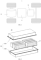
- the vehicle 1 can be a fuel vehicle, a gas vehicle or a new energy vehicle.
- the new energy vehicle can be a pure electric vehicle, a hybrid vehicle, an extended-range vehicle and the like.
- a battery 10 is provided in the interior of a vehicle 1, and can be arranged in the bottom or in the head or back of the vehicle 1.
- the battery 10 can be used to provide electricity to the vehicle 1, for example, the battery 10 can be used as an operating power source for the vehicle 1.
- the vehicle 1 may also include a controller 11 and a motor 12.
- the controller 11 is configured to control the battery 10 to provide electricity to the motor 12, for example, for electricity requirements for the starting, navigation and driving of the vehicle 1.
- the battery 10 may be used not only as an operating power source for the vehicle 1, but also as a driving power source for the vehicle 1, providing driving power to the vehicle 1 in place or in part in place of fuel or natural gas.
- the battery 10 may include a plurality of battery cells.
- a battery cell refers to the smallest unit that constitutes a battery module or battery pack.
- the plurality of battery cells may be in a series connection and/or in a parallel connection via electrode terminals for various applications.
- the battery mentioned in the present disclosure include the battery module or the battery pack.
- the plurality of battery cells can be in a series connection, a parallel connection, or a mixed connection.
- the mixed connection refers to a mixture of the series mixed connection and the parallel mixed connection.
- the plurality of battery cells can be directly formed into a battery pack, or the battery module 20 can be formed first, and then the battery module 20 can be formed into a battery pack.
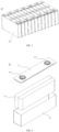
- FIG. 2 is a schematic structural diagram of a battery 10 provided in an embodiment of the present disclosure.
- the battery 10 includes a box 30 and a battery cell (not shown in the figure) accommodated in the box.
- the box 30 may be formed in a single cuboid, a simple three-dimensional structure such as a cylinder or a sphere, or a complex three-dimensional structure composed of a combination of simple three-dimensional structures such as a cuboid, a cylinder or a sphere, which is not limited in the embodiments of the present disclosure.
- the material of the box body 30 can be alloy materials such as aluminum alloy, iron alloy, etc., or polymer materials such as polycarbonate, polyisocyanurate foam, or composite materials such as glass fiber and epoxy resin, which is not limited in the embodiments of the present disclosure.
- the box 30 is configured to accommodate the battery cells and can be of a variety of structures.
- the box 30 may include a first box part 301 and a second box part 302 that are mutually covered.
- the first box part 301 and the second box part 302 jointly define a holding space for holding the battery cells.
- the second box part 302 can have a hollow structure with an opening at one end, the first box part 201 can have a plate structure, and the first box part 301 closes an opening side of the second box part 302 to form the box 30 with the holding space.
- Both the first box part 301 and the second box part 302 may have a hollow structure with an opening at one side.
- first box part 301 covers an opening side of the second box part 302 to form the box 30 with the holding space.
- first box part 301 and the second box part 302 can be in a variety of shapes, such as cylinders, cuboids, etc.
- a sealing component such as sealant, sealing ring, etc., may also be provided between the first box part 301 and the second box part 302.
- the first box part 301 can also be called an upper box cover, and the second box part 302 can also be called a lower box.
- the plurality of battery cells can be in a series connection, a parallel connection, or a mixed connection.
- the mixed connection refers to a mixture of the series mixed connection and the parallel mixed connection.
- the plurality of battery cells can be directly in a series connection, a parallel connection, or a mixed connection, and then the entirety formed by the plurality of battery cells is accommodated in the box 30; of course, the battery module 20 can be formed first by the plurality of battery in a series connection, a parallel connection, or a mixed connection, and then a plurality of battery modules 20 can be in a series connection, a parallel connection, or a mixed connection to form the entirety and accommodated in the box 30.
- FIG. 3 is a schematic structural diagram of a battery module 20 provided in an embodiment of the present disclosure.
- a plurality of battery cells 40 are provided, and the plurality of battery cells 40 are first in series connection, in parallel connection, or in mixed connection to form the battery module 20.
- a plurality of battery modules 21 are in series connection, in parallel connection or in mixed connection to form the entirety, and are accommodated in the box.
- the plurality of battery cells 40 in the battery module 20 can be electrically connected through a bus component, allowing a parallel, series or mixed connection of the plurality of battery cells 40 in the battery module 20.
- the battery cell 40 may include a lithium-ion battery cell, a sodium-ion battery cell, or a magnesium-ion battery cell, etc., which is not limited in the embodiments of the present disclosure.
- the battery cell 40 may be in the shape of a cylinder, a flat body, a rectangular parallelepiped or other shapes, which is not limited in the embodiments of the present disclosure.
- the battery cell 40 are generally divided into three types according to packaging methods: a cylindrical battery cell, a rectangular battery cell and a soft-pack battery cell, which is not limited in the embodiments of the present disclosure. However, for the sake of simplicity of description, the following embodiments take the rectangular battery cell 40 as an example.
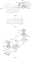
- FIG. 4 is an exploded schematic diagram of a structure of a battery cell 40 provided in some embodiments of the present disclosure.
- the battery cell 40 refers to the smallest unit that constitutes the battery. As shown in FIG. 4 , the battery cell 40 includes an end cover assembly 41, a housing 42 and an electrode assembly 43.
- the end cover assembly 41 refers to a component that covers the opening of the housing 42 to isolate the internal environment of the battery cell 40 from the external environment.
- the shape of the end cover assembly 41 may be adapted to the shape of the housing 42 to fit the housing 42.
- the end cover assembly 41 can be made of a material with a certain hardness and strength (such as aluminum alloy). In this way, the end cover assembly 41 is less likely to be deformed when subjected to extrusion and collision, allowing the battery cell 40 to have better performance, high structural strength, and improved safety performance.
- the end cover assembly 41 may be provided with functional components such as an electrode terminal 415.
- the electrode terminal 415 may be configured to be electrically connected with the electrode assembly 43 for outputting or inputting electrical energy of the battery cell 40.
- the end cover assembly 41 may also be provided with a pressure relief mechanism for releasing the internal pressure when the internal pressure or temperature of the battery cell 40 reaches a threshold.
- the end cover assembly 41 can also be made of various materials, such as copper, iron, aluminum, stainless steel, aluminum alloy, plastic, etc., which are not particularly limited in the embodiments of the present disclosure.
- an insulating member may also be provided inside the end cover assembly 41 and configured to isolate electrical connection components in the housing 42 from the end cover assembly 41 to reduce the risk of short circuit.
- the insulating member may be formed of plastic, rubber, etc.
- the housing 42 is a component configured to cooperate with the end cover assembly 41 to form an internal environment of the battery cell 40.
- the internal environment formed can be configured to accommodate the electrode assembly 43, an electrolyte (not shown in the figure) and other components.
- the housing 42 and the end cover assembly 41 may be independent components, an opening may be provided on the housing 42, and the end cover assembly 41 covers the opening at the opening to form the internal environment of the battery cell 40.
- the end cover assembly 41 and the housing 42 can also be integrated. Specifically, a common connection surface can be formed between the end cover assembly 41 and the housing 42 before other components are put into the housing. When the housing 42 needs to be packaged inside, the end cover assembly 41 covers the housing 42.
- the housing 42 can be of various shapes and sizes, such as rectangular parallelepiped, cylinder, hexagonal prism, etc. Specifically, the shape of the housing 42 can be determined according to the specific shape and size of the electrode assembly 43.
- the housing 42 may be made of a variety of materials, such as copper, iron, aluminum, stainless steel, aluminum alloy, plastic, etc., which are not particularly limited in the embodiments of the present disclosure.
- the electrode assembly 43 is a component in the battery cell 40 where electrochemical reactions occur.
- One or more electrode assemblies 43 may be contained within the housing 42.
- the electrode assembly 43 is mainly formed by a positive electrode sheet and a negative electrode sheet that are wound or stacked, and a separator is usually provided between the positive electrode sheet and the negative electrode sheet.
- Portions of the positive electrode sheet and the negative electrode sheet that contain active materials constitute the main body of the electrode assembly, and portions of the positive electrode sheet and the negative electrode sheet that do not contain active materials each constitute tabs (not shown in the figure).
- the positive tab and the negative tab can be located together at one end of the main body or located at two ends of the main body, respectively.
- the positive active material and negative active material react with the electrolyte, and the electrode tabs are connected to the electrode terminal to form a current loop.
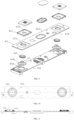
- FIG. 5 is a schematic structural diagram of an end cover assembly provided in some embodiments of the present disclosure
- FIG. 6 is a cross-sectional view taken along line A-A in FIG. 5
- FIG. 7 is a partially enlarged schematic structural diagram of part I as shown in FIG. 6
- FIG. 8 is a schematic structural diagram of a top cover sheet and a first insulating layer in FIG. 7 .
- the end cover assembly 211 can be used to cover the opening of the housing 11 of the battery cell 10 in the embodiments.
- the end cover assembly 41 includes a top cover sheet 411, and the top cover sheet 411 includes a first surface 411a and a second surface 411b that are oppositely arranged along its own thickness direction, a mounting hole 411c provided in the direction and an inner wall surface 411d facing the mounting hole 411c.
- a first insulating layer 412 is provided on the top cover sheet 411, and at least part of the first insulating layer 412 is located on the inner wall surface 411d.
- the top cover sheet 411 of the end cover assembly 41 includes the mounting hole 411c extending through the first surface 411a and the second surface 411b along the thickness direction of the top cover sheet, thus when the end cover assembly 41 is configured for the battery cell, the electrode terminal 415 can be installed on the mounting hole 411c to allow the electrode terminal 415 to lead an electrode tab located inside the battery cell to the outside of the battery cell.
- At least part of the first insulating layer 412 is located on the inner wall surface 411d of the top cover sheet 411 facing the mounting hole 411c, thus when the electrode terminal 415 is located in the mounting hole 411c and is charged, the first insulating layer 412 can guarantee mutual insulation between the electrode terminal 415 and the top cover sheet 411, thereby preventing a safety issue caused by short circuit between the top cover sheet 411 and the electrode terminal 415.
- the material of the top cover sheet 411 may include copper, iron, aluminum, stainless steel, aluminum alloy, etc., to improve the structural rigidity of the top cover sheet 411.
- the top cover sheet 411 may be substantially in the form of a plate, thereby reducing the size of space occupied by the top cover sheet 411 in the thickness direction.
- a structure such as a groove, a through hole, a step hole, may also be provided on the top cover sheet 411 to provide installation positions and/or position limits for components provided on the top cover sheet 411.
- the top cover sheet 411 may include a through hole for an installation of a pressure relief structure.
- the top cover sheet 411 may further include a step groove provided around the mounting hole 411c to provide a limit to the electrode terminal 415 through the step groove.
- the first insulating layer 412 extends from the first surface 411a to the second surface 411b through the inner wall surface 411d.
- part of the first insulating member is distributed on the first surface 411a and the second surface 411b, thereby increasing a creepage distance between the electrode terminal 415 and the top cover sheet 411, and further preventing the safety issue caused by the short circuit between the top cover sheet 411 and the electrode terminal 415.
- At least part of the first insulating layer 412 is located on the first surface 411a, at least part of the first insulating layer 412 is located on the second surface 411b, and at least part of the first insulating layer 412 completely covers the inner wall surface 411d, thereby further preventing the safety issue caused by the short circuit between the top cover sheet 411 and the electrode terminal 415.
- the end cover assembly 41 further includes: a first insulating member 413, at least part of the first insulating member 413 being disposed on the first surface 411a, and the first insulating member 413 including a first through hole 413a communicated with the mounting hole 411c and located in the mounting hole 411c; and a second insulating member 414, at least part of the second insulating member 414 being provided on the second surface 411b, the second insulating member 414 including a second through hole 414a communicated with the mounting hole 411c, and the mounting hole 411c being located in the second through hole 414a.
- a second side surface of the second insulating member 414 facing the second through hole 414a and inner wall surface 411d are spaced apart along a peripheral direction of the mounting hole 411c.
- the first insulating layer 412 includes a first portion 412a located on the first surface 411a and a second portion 412b located on the second surface 411b, and a dimension of the first portion 412a extending along the peripheral direction is smaller than that of the second portion 412b extending along the peripheral direction.
- the peripheral direction is a direction from the center to the inner wall surface 411d of the mounting hole 411c.
- the dimension of the first portion 412a extending in the peripheral direction is a distance from an outer edge of the first portion 412a to the inner wall surface 411d.
- the dimension of the second portion 412b extending in the peripheral direction is a distance from an outer edge of the second portion 412b to the inner wall surface 411d.
- the first insulating member 413 and the second insulating member 414 are provided on two sides of the top cover sheet 411 respectively, and the first through hole 413a on the first insulating member 413 is correspondingly located in the mounting hole 411c. Therefore, a distance between the first insulating member 413 and the electrode terminal 415 is relatively small. Even if an extension dimension of the first portion 412a is relatively small, the insulation performance between the electrode terminal 415 and the top cover sheet 411 can be guaranteed.
- the mounting hole 411c is located in the second through hole 414a on the second insulating member 414, thus at least part of the second surface 411b is exposed by the second through hole 414a.
- An extension dimension of the second portion 412b in the peripheral direction is relatively big, thus the second portion 412b can increase the creepage distance between the electrode terminal 415 and the second surface 411b, to improve the insulation performance between the electrode terminal 415 and the top cover sheet 411.
- first portion 412a and the second portion 412b by different extension dimensions of the first portion 412a and the second portion 412b, materials can be saved and energy saving can be achieved while guaranteeing the insulation performance between the electrode terminal 415 and the top cover sheet 411.
- the first insulating member 413 and the second insulating member 414 can be made of various materials.
- the first insulating member 413 and the second insulating member 414 can be made of insulating materials such as plastic.
- the first insulating member 413 and the second insulating member 414 can be arranged in various positions. For example, as shown in FIGS. 5 to 9 , when the end cover assembly 41 is applied for the battery cell, the first insulating member 413 and the first surface 411a is located on the side of the top cover sheet 411 facing away from the inside of the housing, and the second insulating member 414 and the second surface 411b are located on the side of the top cover sheet 411 facing the inside of the housing.
- the first insulating member 413 may be called upper plastic
- the second insulating member 414 may be called lower plastic.
- FIGS. 10 to 13 in which FIG. 10 is a schematic structural diagram of an end cover assembly 41 provided in another embodiment of the present disclosure; FIG. 11 is a cross-sectional view taken along line B-B in FIG. 10 ; FIG. 12 is a partial enlarged schematic structural diagram of part II in FIG. 11 ; FIG. 13 is a schematic structural diagram of a top cover sheet 411 and a first insulating layer in FIG. 12 As shown in FIGS. 10 to 13 , in which FIG. 10 is a schematic structural diagram of an end cover assembly 41 provided in another embodiment of the present disclosure; FIG. 11 is a cross-sectional view taken along line B-B in FIG. 10 ; FIG. 12 is a partial enlarged schematic structural diagram of part II in FIG. 11 ; FIG. 13 is a schematic structural diagram of a top cover sheet 411 and a first insulating layer in FIG. 12 As shown in FIGS.
- the second insulating member 414 and the second surface 411b are located on the side of the top cover sheet 411 away from the inside of the housing, and the first insulating member 413 and the second surface 411b are located on the side of the top cover sheet 411 away from the housing, the first insulating member 413 and the first surface 411a are located on a side of the top cover sheet 411 facing the inside of the housing.
- the second insulating member 414 may be called upper plastic
- the first insulating member 413 may be called lower plastic.
- the second portion 412b is in lap joint with a surface of the second insulating member 414 facing the top cover sheet 411.
- at least part of the second portion 412b is located between the second insulating member 414 and second surface 411b.
- the first insulating layer 412 and the second insulating member 414 can form a relatively closed insulating space, further preventing the safety issues caused by short circuit between the top cover sheet 411 and the electrode terminal 415.
- the dimension of the second portion 412b extending along the peripheral direction is greater than 1 mm, thereby guaranteeing that the first insulating layer 412 has a sufficiently large size on the second surface 411b to further prevent the safety issue caused by the short circuit between the top cover sheet 411 and the electrode terminal 415.
- the dimension of the first portion 412a extending along the peripheral direction is greater than 0.5 mm, thereby guaranteeing that the first insulating layer 412 and the second insulating member 414 form a closed insulating space to further prevent the safety issue caused by the short circuit between the top cover sheet 411 and the electrode terminal 415.
- the end cover assembly 41 further includes: an electrode terminal 415, installed on the top cover sheet 411; and a sealing member 416, at least part of which is located in the mounting hole 411c.
- the electrode terminal 415 includes an abutment surface 415a that abuts with the sealing member 416, and at least part of the abutment surface 415a is provided with a second insulating layer 417.
- the insulation performance between the electrode terminal 415 and the top cover sheet 411 can be further ensured, and the risk of sparks on the electrode terminal 415 sputtering from between the electrode terminal 415 and the sealing member 416 to the top cover sheet 411 is reduced.
- the material of the sealing member 416 may be insulating material such as rubber.
- the sealing member 416 is annular and fits the inner wall surface 411d.
- the electrode terminal 415 can extend into the sealing member 416 and be connected to an electrode tab of the electrode assembly, or an adapting piece can be connected between the electrode tab and the electrode terminal 415, and the adapting piece can extend into the sealing member 416 and be connected with the electrode terminal 415.
- the first insulating member 413 and the sealing member 416 are connected with each other via a lap joint in the mounting hole 411c.
- the first insulating member 413 and the sealing member 416 can enclose and form a relatively closed insulating space.
- the electrode terminal 415 or the adapting piece is located in the sealing member 416, the risk of sparks on the electrode terminal 415 or the adapting piece transmitted to the top cover sheet 411 is reduced be ensured to form a relatively, thereby further preventing the safety issue caused by the short circuit between the top cover sheet and the electrode terminal.
- the first insulating member 413 can be in a lap joint with the sealing member 416 in many ways.
- a protrusion 413b is provided on a side of the first insulating member 413 facing the through hole, protrudes toward the second insulating member 414 and extends into the mounting hole 411c.
- At least part of the sealing member 416 is located between the protrusion 413b and the inner wall surface 411d, or at least part of the protrusion 413b is located between the sealing member 416 and the inner wall surface 411d, so that the protrusion 413b can be in lap joint with the sealing member 416.
- the sealing member 416 includes a first segment 416a located at the mounting hole 411c and a second segment extending from the first segment 416a in a direction away from the mounting hole 411c, and the second segment 416b is located in the second through hole 414a and is in lap joint with part of the second surface 411b.
- the sealing member 416 includes the first segment 416a and the second segment 416b. With the second segment 416b and the second segment 416b covering at least part of the second surface 411b, the creepage distance between the electrode terminal 415 and a surface of the top cover sheet 411 is further increased, and the safety issue caused by short circuit between the top cover sheet 411 and the electrode terminal 415 is prevented. In addition, with the second segment 416b, a contact distance between the sealing member 416 and the top cover sheet 411 can also be increased, guaranteeing the stability of the relative position between the sealing member 416 and the top cover sheet 411.
- the electrode terminal 415 can be arranged in many ways. As shown in FIGS. 5 to 9 , at least part of the electrode terminal 415 can extend into the mounting holes 411c; in other embodiments, as shown in FIGS. 10 to 14 , the electrode terminal 415 can be connected to the electrode tab of a battery core assembly through an adapting piece, and the adapting piece can extend into the mounting hole 411c.
- the electrode terminal 415 includes a connecting segment 415b and an abutment segment 415c.
- the connecting segment 415b is located in the mounting hole 411c.
- the abutment section 415c extends from the connecting segment 415b in a direction away from the mounting hole 411c. At least part of the abutment segment 415c is abutted against the sealing member 416, and at least part of the second insulating layer 417 is provided on the abutment segment 415c.
- the electrode terminal 415 is located in the mounting hole 411c, and the electrode terminal 415 includes the connecting segment 415b and the abutment segment 415c, which can improve the stability of the connection between the electrode terminal 415 and the top cover sheet 411.
- the abutment segment 415c is abutted against the sealing member 416, and the second insulating layer 417 is provided on the abutment segment 415c, thereby further preventing the safety issue caused by the short circuit between the top cover sheet 411 and the electrode terminal 415.
- the radial size of the abutment segment 415c of the electrode terminal 415 is greater than the radial size of the connecting segment 415b, and the radial size of the abutment segment 415c is greater than the aperture of the mounting hole 411c, allowing the abutment segment 415c can be stopped outside the mounting hole 411c, and guaranteeing the stability of the relative position between the electrode terminal 415 and the top cover sheet 411.
- the connecting segment 415b includes a bottom surface 415e facing away from the abutment segment 415c and a peripheral side surface 415d connecting the bottom surface 415e and the abutment segment 415c, and at least part of the second insulating layer 417 is provided on the peripheral side surface 415d of the connecting segment 415b.
- the insulation between the electrode terminal 415 and the inner wall surface 411d of the top cover sheet 411 can be guaranteed, thereby further preventing the safety issue caused by short circuit between the top cover sheet 411 and electrode terminal 415.
- At least a part of the second insulating layer 417 is provided on the bottom surface 415e, thereby further improving the insulation between the electrode terminal 415 and the top cover sheet 411, and preventing the safety issue caused by short circuit between the top cover sheet 411 and the electrode terminal 415.
- the second insulating layer 417 includes a third portion 417a located at the abutment segment 415c.
- the third portion 417a is annular and surrounds the connecting segment 415b.
- the third portion 417a around the connecting segment 415b it is possible to guarantee the insulation between the abutment segment 415c and the top cover sheet 411 different positions in the peripheral direction, further preventing the safety issue caused by the short circuit between the top cover sheet 411 and the electrode terminal 415.
- the abutment segment 415c is roughly in shape of a square prism, and the connecting segment 415b is cylindrical.
- the third portion 417a provided on the abutment segment 415c can surround the connecting segment 415b in an annular shape, and the third portion 417a is internally tangent to the edges of the abutment segment 415c, which can increase the distribution area of the third portion 417a and further prevent the safety issue caused by the short circuit between the top cover sheet 411 and the electrode terminal 415.
- the electrode terminal 415 is located on the side where the second surface 411b is located, and the second insulating layer 417 is arranged in an annular shape on the abutment surface 415a to improve the insulation between the electrode terminal 415 and the top cover sheet 411 at different positions in the peripheral direction.
- the adapting piece can be electrically connected to the electrode terminal 415 through the mounting hole 411c, and the electrode terminal 415 is abutted against at least part of the second surface 411b.
- the second insulating layer 417 is arranged to be annular on the abutment surface 415a.
- the second insulation layer 417 is set around the mounting hole 411c.
- the top cover sheet 411 is provided with a limiting step around the mounting hole 411c, and at least part of the electrode terminal 415 is located within the limiting step.
- the thickness of the first insulating layer 412 and/or the second insulating layer 417 is 2 ⁇ m-100 ⁇ m, to avoid insufficient insulation performance caused by the thickness of the first insulating layer 412 and/or the second insulating layer 417 being too small, or the thickness of the first insulating layer 412 and/or the second insulating layer 417 being too large, which affects the assembly between the top cover sheet 411 and the electrode terminal 415.
- the present disclosure also provides a battery cell, including the end cover assembly 41 as described in any of the above solutions.
- the present disclosure also provides a battery including the battery cell as described in any of the above solutions.
- the present disclosure also provides an electrical apparatus including the battery as described in any of the above solutions to provide electrical energy to the electrical apparatus.
- the electrical apparatus can be any of the aforementioned devices or systems that use the battery.
- the end cover assembly 41 provided in the embodiments includes the top cover sheet 411, the first insulating member 413, the second insulating member 414, the electrode terminal 415, and the sealing member 416.
- the top cover sheet 411 includes the first surface 411a and the second surface 411b arranged relative to each other along a thickness direction of the end cover sheet, the mounting hole 411c arranged along the thickness direction, and the inner wall surface 411d arranged facing the mounting hole 411c.
- the first insulating layer 412 is provided on the top cover sheet 411, and extends from the first surface 411a to the second surface 411b through the inner wall surface 411d.
- At least part of the first insulating member 413 is provided on the first surface 411a, and the first insulating member 413 includes the first through hole 413a communicated with the mounting hole 411c located inside the mounting hole 411c.
- At least part of the second insulating member 414 is provided on the second surface 411b, and the second insulating member 414 includes the second through hole 414a communicated with the mounting hole 411c.
- the mounting hole 411c is located inside the second through hole 414a, and a second side surface of the second insulating member 414 facing the second through hole 414a and the inner wall surface 411d are spaced in the peripheral direction of the mounting hole 411c.
- the first insulating layer 412 includes the first portion 412a located on the first surface 411a and the second portion 412b located on the second surface 411b.
- the dimension of the first portion 412a extending along the peripheral direction is smaller than that of the second portion 412b extending along the peripheral direction.
- the second portion 412b is in lap joint with the surface of the second insulating member 414 facing the top cover sheet 411.
- the dimension of the second portion 412b extending the peripheral direction is greater than 1mm, and the dimension of the first portion 412a extending the peripheral direction is greater than 0.5mm.
- the electrode terminal 415 is mounted in the mounting hole 411c, and at least part of the sealing member 416 is located in the mounting hole 411c.
- the electrode terminal 415 includes the abutment surface 415a abutted against the sealing member 416, and at least part of the abutment surface 415a is provided with the second insulating layer 417.
- the first insulating member 413 is in lap joint with the sealing member 416 in the mounting hole 411c.
- the sealing member 416 includes the first segment 416a located in the mounting hole 411c and the second segment 416b extending from the first segment 416a in a direction away from the mounting hole 411c.
- the second segment 416b is located in the second through hole 414a and is abutted against part of the second surface 411b.
- the electrode terminal 415 includes the connecting segment 415b and the abutment segment 415c, and the connecting segment 415b located in the mounting hole 411c.
- the abutment segment 415c is formed by an extension of the connecting segment 415b in a direction away from the mounting hole 411c, and at least part of the abutment segment 415c is abutted against the sealing member 416.
- the connecting segment 415b includes the bottom surface 415e away from the abutment segment 415c, and the peripheral side surface 415d connecting the bottom surface 415e and the abutting section 415c. At least part of the second insulating layer 417 is provided on the peripheral side surface 415d and the bottom surface 415e of the connecting segment 415b.
- the end cover assembly 41 provided in the embodiments includes the top cover sheet 411, the first insulating member 413, the second insulating member 414, the electrode terminal 415, and the sealing member 416.
- the top cover sheet 411 includes the first surface 411a and the second surface 411b arranged relative to each other along a thickness direction of the end cover sheet, the mounting hole 411c arranged along the thickness direction, and the inner wall surface 411d arranged facing the mounting hole 411c.
- the first insulating layer 412 is provided on the top cover sheet 411, and extends from the first surface 411a to the second surface 411b through the inner wall surface 411d.
- At least part of the first insulating member 413 is provided on the first surface 411a, and the first insulating member 413 includes the first through hole 413a communicated with the mounting hole 411c located inside the mounting hole 411c.
- At least part of the second insulating member 414 is provided on the second surface 411b, and the second insulating member 414 includes the second through hole 414a communicated with the mounting hole 411c.
- the mounting hole 411c is located inside the second through hole 414a, and a second side surface of the second insulating member 414 facing the second through hole 414a and the inner wall surface 411d are spaced in the peripheral direction of the mounting hole 411c.
- the first insulating layer 412 includes the first portion 412a located on the first surface 411a and the second portion 412b located on the second surface 411b.
- the dimension of the first portion 412a extending along the peripheral direction is smaller than that of the second portion 412b extending along the peripheral direction.
- the second portion 412b is in lap joint with the surface of the second insulating member 414 facing the top cover sheet 411.
- the dimension of the second portion 412b extending the peripheral direction is greater than 1mm, and the dimension of the first portion 412a extending the peripheral direction is greater than 0.5mm.
- the electrode terminal 415 is located on the side where the second surface 411b is located, and the second insulating layer 417 is arranged on the abutment surface 415a in an annular shape. At least part of the sealing member 416 is located in the mounting hole 411c, and the electrode terminal 415 includes the abutment surface 415a that is abutted against the sealing member 416. At least part of the abutment surface 415a is provided with the second insulating layer 417.
- the first insulating member 413 is in a lap joint with the sealing member 416 in the mounting hole 411c.
- the sealing member 416 includes the first segment 416a located in the mounting hole 411c and the second segment 416b extending from the first segment 416a in a direction away from the mounting hole 411c.
- the second segment 416b is located in the second through hole 414a and is abutted against part of the second surface 411b.
Landscapes
- Chemical & Material Sciences (AREA)
- Chemical Kinetics & Catalysis (AREA)
- Electrochemistry (AREA)
- General Chemical & Material Sciences (AREA)
- Connection Of Batteries Or Terminals (AREA)
Applications Claiming Priority (1)
| Application Number | Priority Date | Filing Date | Title |
|---|---|---|---|
| PCT/CN2022/093122 WO2023220880A1 (zh) | 2022-05-16 | 2022-05-16 | 端盖组件、电池单体、电池及用电装置 |
Publications (2)
| Publication Number | Publication Date |
|---|---|
| EP4475331A1 true EP4475331A1 (de) | 2024-12-11 |
| EP4475331A4 EP4475331A4 (de) | 2025-04-16 |
Family
ID=88834437
Family Applications (1)
| Application Number | Title | Priority Date | Filing Date |
|---|---|---|---|
| EP22941931.2A Pending EP4475331A4 (de) | 2022-05-16 | 2022-05-16 | Endkappenanordnung, batteriezelle, batterie und elektrische vorrichtung |
Country Status (4)
| Country | Link |
|---|---|
| US (1) | US20250015466A1 (de) |
| EP (1) | EP4475331A4 (de) |
| CN (1) | CN117642926A (de) |
| WO (1) | WO2023220880A1 (de) |
Cited By (1)
| Publication number | Priority date | Publication date | Assignee | Title |
|---|---|---|---|---|
| CN120473620A (zh) * | 2025-07-11 | 2025-08-12 | 深圳海辰储能科技有限公司 | 一种下塑胶、端盖组件、储能装置及用电设备 |
Families Citing this family (2)
| Publication number | Priority date | Publication date | Assignee | Title |
|---|---|---|---|---|
| CN222813904U (zh) * | 2024-02-04 | 2025-04-29 | 宁德时代新能源科技股份有限公司 | 电池、电池模块和用电设备 |
| CN117832783B (zh) * | 2024-03-06 | 2024-05-28 | 厦门海辰储能科技股份有限公司 | 下塑胶、端盖组件、储能装置和用电设备 |
Family Cites Families (6)
| Publication number | Priority date | Publication date | Assignee | Title |
|---|---|---|---|---|
| JP2870152B2 (ja) * | 1990-08-06 | 1999-03-10 | 松下電器産業株式会社 | 絶縁端子付き封口板の製法とそれを用いた密閉形アルカリ電池 |
| KR20010017098A (ko) * | 1999-08-07 | 2001-03-05 | 김순택 | 각형 밀폐전지 |
| JP6268911B2 (ja) * | 2013-10-03 | 2018-01-31 | 睦月電機株式会社 | 密閉型電気化学デバイス用封口体 |
| JP6907509B2 (ja) * | 2016-11-10 | 2021-07-21 | 株式会社Gsユアサ | 蓄電素子、導電部材及び蓄電素子の製造方法 |
| CN216161825U (zh) * | 2021-09-14 | 2022-04-01 | 恒大新能源技术(深圳)有限公司 | 分体式盖板、电池模组及电池包 |
| CN217788578U (zh) * | 2022-05-16 | 2022-11-11 | 宁德时代新能源科技股份有限公司 | 端盖组件、电池单体、电池及用电装置 |
-
2022
- 2022-05-16 EP EP22941931.2A patent/EP4475331A4/de active Pending
- 2022-05-16 WO PCT/CN2022/093122 patent/WO2023220880A1/zh not_active Ceased
- 2022-05-16 CN CN202280049183.9A patent/CN117642926A/zh active Pending
-
2024
- 2024-09-19 US US18/890,558 patent/US20250015466A1/en active Pending
Cited By (1)
| Publication number | Priority date | Publication date | Assignee | Title |
|---|---|---|---|---|
| CN120473620A (zh) * | 2025-07-11 | 2025-08-12 | 深圳海辰储能科技有限公司 | 一种下塑胶、端盖组件、储能装置及用电设备 |
Also Published As
| Publication number | Publication date |
|---|---|
| EP4475331A4 (de) | 2025-04-16 |
| US20250015466A1 (en) | 2025-01-09 |
| WO2023220880A1 (zh) | 2023-11-23 |
| CN117642926A (zh) | 2024-03-01 |
Similar Documents
| Publication | Publication Date | Title |
|---|---|---|
| US20250015426A1 (en) | Housing, battery cell, battery, and power consuming device | |
| US11757161B2 (en) | Battery cell, battery and electricity consuming device | |
| US20250015466A1 (en) | End cover assembly, battery cell and battery | |
| CN217788578U (zh) | 端盖组件、电池单体、电池及用电装置 | |
| US20240283099A1 (en) | Battery cell, battery, power consumption device, and method and device for producing battery cell | |
| US20240347826A1 (en) | Shell, battery cell, battery and electricity consuming device | |
| US12519183B2 (en) | Battery cell, battery, and electrical device | |
| CN218414802U (zh) | 电池单体、电池及用电装置 | |
| EP4456283A1 (de) | Kastenkörper einer batterie sowie batterie und elektrische vorrichtung | |
| US20240429546A1 (en) | End cover of battery cell, end cover assembly, battery cell, battery, and electric apparatus | |
| WO2024008054A1 (zh) | 电池单体、电池及用电装置 | |
| US20240243450A1 (en) | Adapter assembly, battery cell, battery, and electrical device | |
| US20250087848A1 (en) | Battery cell, battery and electrical equipment | |
| US20250015467A1 (en) | End cover assembly, battery cell and battery | |
| US20250079651A1 (en) | Battery Cell, Battery and Electrical Equipment | |
| WO2024000785A1 (zh) | 电池单体、电池和用电装置 | |
| WO2024020766A1 (zh) | 电池单体、电池、用电装置及电池单体的制造方法 | |
| US20240055705A1 (en) | Battery cell, battery, power consuming apparatus, and method and apparatus for manufacturing battery cell | |
| US20250023171A1 (en) | Battery and electric-powered device | |
| CN220569775U (zh) | 电池单体、电池以及用电装置 | |
| WO2024016453A1 (zh) | 电池单体、电池及用电装置 | |
| US20250096439A1 (en) | Battery cell, battery and electric device | |
| CN221226309U (zh) | 电池单体、电池和用电设备 | |
| EP4401179A1 (de) | Batteriezelle, batterie und elektrische vorrichtung | |
| CN117941165B (zh) | 电池单体、电池及用电设备 |
Legal Events
| Date | Code | Title | Description |
|---|---|---|---|
| STAA | Information on the status of an ep patent application or granted ep patent |
Free format text: STATUS: THE INTERNATIONAL PUBLICATION HAS BEEN MADE |
|
| PUAI | Public reference made under article 153(3) epc to a published international application that has entered the european phase |
Free format text: ORIGINAL CODE: 0009012 |
|
| STAA | Information on the status of an ep patent application or granted ep patent |
Free format text: STATUS: REQUEST FOR EXAMINATION WAS MADE |
|
| 17P | Request for examination filed |
Effective date: 20240905 |
|
| AK | Designated contracting states |
Kind code of ref document: A1 Designated state(s): AL AT BE BG CH CY CZ DE DK EE ES FI FR GB GR HR HU IE IS IT LI LT LU LV MC MK MT NL NO PL PT RO RS SE SI SK SM TR |
|
| A4 | Supplementary search report drawn up and despatched |
Effective date: 20250317 |
|
| RIC1 | Information provided on ipc code assigned before grant |
Ipc: H01M 50/586 20210101ALI20250311BHEP Ipc: H01M 50/15 20210101ALI20250311BHEP Ipc: H01M 50/593 20210101AFI20250311BHEP |
|
| DAV | Request for validation of the european patent (deleted) | ||
| DAX | Request for extension of the european patent (deleted) |