EP4475293A2 - Ensemble couvercle d'extrémité, dispositif de stockage d'énergie et appareil électrique - Google Patents
Ensemble couvercle d'extrémité, dispositif de stockage d'énergie et appareil électrique Download PDFInfo
- Publication number
- EP4475293A2 EP4475293A2 EP24170473.3A EP24170473A EP4475293A2 EP 4475293 A2 EP4475293 A2 EP 4475293A2 EP 24170473 A EP24170473 A EP 24170473A EP 4475293 A2 EP4475293 A2 EP 4475293A2
- Authority
- EP
- European Patent Office
- Prior art keywords
- insulator
- loosening
- cover plate
- hole
- end cover
- Prior art date
- Legal status (The legal status is an assumption and is not a legal conclusion. Google has not performed a legal analysis and makes no representation as to the accuracy of the status listed.)
- Pending
Links
Images








Classifications
-
- H—ELECTRICITY
- H01—ELECTRIC ELEMENTS
- H01M—PROCESSES OR MEANS, e.g. BATTERIES, FOR THE DIRECT CONVERSION OF CHEMICAL ENERGY INTO ELECTRICAL ENERGY
- H01M50/00—Constructional details or processes of manufacture of the non-active parts of electrochemical cells other than fuel cells, e.g. hybrid cells
- H01M50/10—Primary casings; Jackets or wrappings
- H01M50/172—Arrangements of electric connectors penetrating the casing
- H01M50/174—Arrangements of electric connectors penetrating the casing adapted for the shape of the cells
- H01M50/176—Arrangements of electric connectors penetrating the casing adapted for the shape of the cells for prismatic or rectangular cells
-
- H—ELECTRICITY
- H01—ELECTRIC ELEMENTS
- H01M—PROCESSES OR MEANS, e.g. BATTERIES, FOR THE DIRECT CONVERSION OF CHEMICAL ENERGY INTO ELECTRICAL ENERGY
- H01M50/00—Constructional details or processes of manufacture of the non-active parts of electrochemical cells other than fuel cells, e.g. hybrid cells
- H01M50/10—Primary casings; Jackets or wrappings
- H01M50/147—Lids or covers
-
- H—ELECTRICITY
- H01—ELECTRIC ELEMENTS
- H01M—PROCESSES OR MEANS, e.g. BATTERIES, FOR THE DIRECT CONVERSION OF CHEMICAL ENERGY INTO ELECTRICAL ENERGY
- H01M50/00—Constructional details or processes of manufacture of the non-active parts of electrochemical cells other than fuel cells, e.g. hybrid cells
- H01M50/10—Primary casings; Jackets or wrappings
- H01M50/147—Lids or covers
- H01M50/148—Lids or covers characterised by their shape
- H01M50/15—Lids or covers characterised by their shape for prismatic or rectangular cells
-
- H—ELECTRICITY
- H01—ELECTRIC ELEMENTS
- H01M—PROCESSES OR MEANS, e.g. BATTERIES, FOR THE DIRECT CONVERSION OF CHEMICAL ENERGY INTO ELECTRICAL ENERGY
- H01M50/00—Constructional details or processes of manufacture of the non-active parts of electrochemical cells other than fuel cells, e.g. hybrid cells
- H01M50/50—Current conducting connections for cells or batteries
- H01M50/543—Terminals
- H01M50/552—Terminals characterised by their shape
- H01M50/553—Terminals adapted for prismatic, pouch or rectangular cells
-
- H—ELECTRICITY
- H01—ELECTRIC ELEMENTS
- H01M—PROCESSES OR MEANS, e.g. BATTERIES, FOR THE DIRECT CONVERSION OF CHEMICAL ENERGY INTO ELECTRICAL ENERGY
- H01M50/00—Constructional details or processes of manufacture of the non-active parts of electrochemical cells other than fuel cells, e.g. hybrid cells
- H01M50/50—Current conducting connections for cells or batteries
- H01M50/543—Terminals
- H01M50/564—Terminals characterised by their manufacturing process
- H01M50/567—Terminals characterised by their manufacturing process by fixing means, e.g. screws, rivets or bolts
-
- H—ELECTRICITY
- H01—ELECTRIC ELEMENTS
- H01M—PROCESSES OR MEANS, e.g. BATTERIES, FOR THE DIRECT CONVERSION OF CHEMICAL ENERGY INTO ELECTRICAL ENERGY
- H01M50/00—Constructional details or processes of manufacture of the non-active parts of electrochemical cells other than fuel cells, e.g. hybrid cells
- H01M50/50—Current conducting connections for cells or batteries
- H01M50/572—Means for preventing undesired use or discharge
- H01M50/584—Means for preventing undesired use or discharge for preventing incorrect connections inside or outside the batteries
- H01M50/59—Means for preventing undesired use or discharge for preventing incorrect connections inside or outside the batteries characterised by the protection means
-
- H—ELECTRICITY
- H01—ELECTRIC ELEMENTS
- H01M—PROCESSES OR MEANS, e.g. BATTERIES, FOR THE DIRECT CONVERSION OF CHEMICAL ENERGY INTO ELECTRICAL ENERGY
- H01M50/00—Constructional details or processes of manufacture of the non-active parts of electrochemical cells other than fuel cells, e.g. hybrid cells
- H01M50/50—Current conducting connections for cells or batteries
- H01M50/572—Means for preventing undesired use or discharge
- H01M50/584—Means for preventing undesired use or discharge for preventing incorrect connections inside or outside the batteries
- H01M50/59—Means for preventing undesired use or discharge for preventing incorrect connections inside or outside the batteries characterised by the protection means
- H01M50/593—Spacers; Insulating plates
-
- Y—GENERAL TAGGING OF NEW TECHNOLOGICAL DEVELOPMENTS; GENERAL TAGGING OF CROSS-SECTIONAL TECHNOLOGIES SPANNING OVER SEVERAL SECTIONS OF THE IPC; TECHNICAL SUBJECTS COVERED BY FORMER USPC CROSS-REFERENCE ART COLLECTIONS [XRACs] AND DIGESTS
- Y02—TECHNOLOGIES OR APPLICATIONS FOR MITIGATION OR ADAPTATION AGAINST CLIMATE CHANGE
- Y02E—REDUCTION OF GREENHOUSE GAS [GHG] EMISSIONS, RELATED TO ENERGY GENERATION, TRANSMISSION OR DISTRIBUTION
- Y02E60/00—Enabling technologies; Technologies with a potential or indirect contribution to GHG emissions mitigation
- Y02E60/10—Energy storage using batteries
Definitions
- the present disclosure relates to the field of energy storage technologies, and more particularly, to an end cover assembly, an energy storage device, and an electric apparatus.
- the injection molding overmolded pole tends to move towards an interior of the battery, resulting in easy leakage of an electrolyte due to a reduction in a compression of a sealing ring.
- the pole moves towards the interior of the battery, the pole will move into an insulator, resulting in poor welding of a BUSbar.
- Embodiments of the present disclosure provide an end cover assembly, an energy storage device, and an electric apparatus to solve at least one of the above-mentioned technical problems.
- the end cover assembly includes a cover plate, a pole, an insulator, and an anti-loosening structure.
- the cover plate has a first through hole.
- the pole includes a pole body.
- the pole body passes through the first through hole and is provided with a first thread at an outer peripheral surface of the pole body.
- the insulator is provided on the cover plate and has a second through hole.
- the second through hole has a hole wall provided with a second thread.
- the pole body passes through the second through hole, and the first thread is connected to the second thread.
- the anti-loosening structure includes a first anti-loosening portion and a second anti-loosening portion that are engaged with and connected to each other to prevent the insulator from loosening.
- the insulator and the pole body of the pole are connected to the first thread through the second thread. Therefore, without an injection molding overmolding process, a movement of the pole towards an interior of a battery can be avoided. In addition, reliability of a connection between the insulator and the pole body of the pole can be ensured by the anti-loosening structure.
- the first anti-loosening portion is disposed at the cover plate.
- the second anti-loosening portion is disposed at the insulator.
- the first anti-loosening portion limits the insulator above the cover plate.
- the insulator since the insulator is connected to the pole through the thread, the insulator cannot loosen.
- the plurality of tooth is received in the plurality of tooth grooves, which can prevent the insulator from loosening by the cover plate.
- each of the plurality of tooth grooves includes a first engagement surface and a first guide surface.
- the first engagement surface is connected to the first guide surface and extends in a thickness direction of the cover plate.
- the first guide surface is inclined away from the cover plate from the first engagement surface in a direction perpendicular to the thickness direction of the cover plate.
- Each of the plurality of tooth includes a second engagement surface and a second guide surface.
- the second engagement surface is connected to the second guide surface and extends in the thickness direction of the cover plate.
- the second guide surface is inclined away from the cover plate from the second engagement surface in the direction perpendicular to the thickness of the cover plate.
- the first engagement surface abuts with the second engagement surface to prevent the insulator from loosening.
- the first guide surface is attached to the second guide surface.
- the first anti-loosening portion includes one of an engagement groove and an elastic sheet.
- the second anti-loosening portion includes another one of the engagement groove and the elastic sheet.
- the elastic sheet is at least partially located at the engagement groove to prevent the insulator from loosening.
- the insulator can be prevented from loosening through the engagement between the engagement groove and the elastic sheet, and thus high anti-loosening performance can be realized.
- the cover plate has a first surface and a second surface opposite to each other.
- the first through hole penetrates the first surface and the second surface.
- the first anti-loosening portion includes an edge portion of the cover plate surrounding the first through hole.
- the insulator has a third surface and a fourth surface opposite to each other. The fourth surface abuts with the first surface.
- the second anti-loosening portion includes a hook connected to the fourth surface. The hook has a hooking portion hooking the edge portion to prevent the insulator from loosening.
- the insulator can be prevented from loosening by hooking the hook to the edge portion, and thus high anti-loosening performance can be realized. Meanwhile, metal debris can be avoided from being generated due to scratching between the insulator and the cover plate, thus an internal short-circuit can be avoided.
- the cover plate has an accommodation groove formed at a surface of the cover plate.
- the first through hole is in communication with the accommodation groove.
- the insulator and the pole body are at least partially accommodated in the accommodation groove.
- the first anti-loosening portion is disposed at a bottom surface of the accommodation groove.
- the first anti-loosening portion is disposed at the outer peripheral surface of the pole body.
- the second anti-loosening portion is disposed at the hole wall of the second through hole.
- the insulator can be prevented from loosening by the first anti-loosening portion at the pole body and the second anti-loosening portion of the insulator.
- the first anti-loosening portion includes one of a groove and a protrusion.
- the second anti-loosening portion includes another one of the groove and the protrusion.
- the protrusion extends in a radial direction of the pole body and is at least partially located in the groove to prevent the insulator from loosening.
- the insulator can be prevented from loosening through the engagement between the groove and the protrusion, and thus the high anti-loosening performance can be realized.
- the insulator is of a cylindrical or polygon prism shape.
- the insulator can be adapted to different fastening tools.
- an electric apparatus includes the above-mentioned energy storage device.
- the energy storage device is configured to supply power to the electric apparatus.
- the first feature "on” or “under” the second feature can mean that the first feature is in direct contact with the second feature, or the first feature and the second feature are not in direct contact but are in contact through another feature between them.
- the first feature "above” the second feature can mean that the first feature is directly above or obliquely above the second feature, or simply mean that the level of the first feature is higher than that of the second feature.
- the first feature "below” the second feature can mean that the first feature is directly below or obliquely below the second feature, or simply mean that the level of the first feature is smaller than that of the second feature.
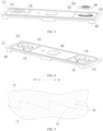
- an end cover assembly 100 includes a cover plate 12, a pole 14, an insulator 16, and an anti-loosening structure 18.
- the cover plate 12 has a first through hole 20.
- the pole 14 includes a pole body 24.
- the pole body 24 passes through the first through hole 20, and is provided with a first thread 26 at an outer peripheral surface of the pole body 24.
- the insulator 16 is provided on the cover plate 12 and has a second through hole 28.
- the second through hole 28 has a hole wall provided with a second thread 30.
- the pole body 24 passes through the second through hole 28.
- the first thread 26 is connected to the second thread 30.
- the anti-loosing structure 18 includes a first anti-loosing portion 32 and a second anti-loosing portion 34.
- the first anti-loosing portion 32 and a second anti-loosing portion 34 are engaged with and connected to each other to prevent the insulator 16 from loosening.
- the insulator 16 and the pole body 24 of the pole 16 are connected to the first thread 26 through the second thread 30. Therefore, without an injection molding overmolding process, a movement of the pole 14 towards an interior of a battery can be avoided. In addition, reliability of a connection between the insulator 16 and the pole body 24 of the pole 14 can be ensured by the anti-loosening structure 18.
- a material of the cover plate 12 and a shape of the first through hole 20 are not limited in the present disclosure.
- the cover plate 12 may be a plain aluminum sheet, and the first through hole 20 may be a circular hole.
- the cover plate 12 has a first surface 36 and a second surface 38 opposite to each other.
- the first through hole 20 penetrates the first surface 36 and the second surface 38.
- the first surface 36 is an upper surface
- the second surface 38 is a lower surface.
- the pole 14 further includes a base 40 connected to the pole body 24.
- the pole 14 may be made of metal.
- the pole body 24 is of a cylindrical or polygon prism shape, which is not limited herein. In FIG. 2 , the pole body 24 is of a cylindrical shape.
- the pole 14 at a right side may be a negative pole.
- the negative pole consists of a negative block 42 and a negative welding ring 44 that are welded.
- the negative block 42 and the negative welding ring 44 are connected to each other through laser welding.
- the negative block 42 may be a composite material of copper and aluminum, and the negative welding ring 44 may be a copper ring.
- the copper of the negative block 42 and the copper ring are connected to each other through the laser welding, which can ensure connection reliability.
- the negative block 42 and the negative welding ring 44 are first welded by a laser, and then the first thread 26 is formed at the pole body 24 through a thread rolling process or a turning process.
- the negative welding ring 44 is formed as the base 40, and the negative block 42 is formed as the pole body 24.
- the pole 14 at a left side is a positive pole.
- the positive pole manufacturing process is to form the first thread 26 on the pole body 24 through the thread rolling or the turning after stamping.
- the positive pole has an integral structure. Parts and components of the pole 14 are manufactured through high-efficiency and low-cost processes, which can reduce cost while lowering difficulty in the automated assembly. Therefore, high-efficiency automated manufacturing can be realized, which reduces manufacturing cost and improves a qualified rate of the product, enabling the whole cost of the end cover assembly 100 to be reduced by about 28%.
- the insulator 16 may be an upper plastic member of the end cover assembly 100.
- the insulator may be an individually injection-molded component rather than an insulator formed by an overmolding process.
- the insulator 16 may separate the cover plate 12 from the pole 14, and increase a creepage distance between the cover plate 12 and the pole 14, thereby ensuring the safety of the battery cell.
- the second through hole 28 is a circular hole, and a second thread 30 is formed at a hole wall of the second through hole 28.
- the pole body 24 passes through the first through hole 20 and protrudes from the cover plate 12.
- the insulator 16 may be mounted to the pole body 24 from a position above the cover plate 12, and then the insulator 16 rotates clockwise (in a tightening direction).
- the second thread 30 engages with the first thread 26 to allow the insulator 16 to screw into the pole body 24.
- the first anti-loosing portion 32 and the second anti-loosing portion 34 may be engaged and connected to each other to prevent the insulator 16 from loosening.
- the first anti-loosing portion 32 and the second anti-loosing portion 34 can prevent the insulator 16 from rotating counterclockwise (in a loosening direction), thereby ensuring the connection reliability between the insulator 16 and the pole body 24.
- the end cover assembly 100 further includes an explosion-proof valve 46, a lower plastic member 48, a sealing ring 50, and a connection sheet 51.
- the lower plastic member 48 is connected to a lower surface of the cover plate 12, and the explosion-proof valve 46 is mounted at the cover plate 12.
- the sealing ring 50 is arranged around the pole body 24.
- the base 40 of the pole 14 is pressed against the lower surface of the cover plate 12.
- the connection sheet 51 is connected to an end of the pole.
- the first anti-loosening portion 32 is disposed at the cover plate 12.
- the second anti-loosening portion 34 is disposed at the insulator 16.
- the first anti-loosening portion 32 limits the insulator 16 above the cover plate 12. Meanwhile, since the insulator 16 and the pole 14 are connected to each other by the thread, the insulator 16 cannot loosen.
- the insulator 16 is a separate component, and the insulator 16 as a separate component is connected to the pole 14 by the thread.
- the end cover assembly 100 is mounted at an opening at a side of a housing, and the cover plate 12 is fixedly connected to the housing.
- the first anti-loosening portion 32 is provided at the cover plate 12, and the second anti-loosening portion 34 is provided at the insulator 16. Therefore, the insulator 16 has a high anti-loosening performance.
- the first anti-loosening portion 32 may be connected to the cover plate 12 and formed into an integral structure with the cover plate 12.
- the second anti-loosening portion 34 may be connected to the insulator 16 and formed into an integral structure with the insulator. Therefore, an anti-loosening effect can be achieved.
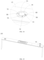
- the first anti-loosening portion 32 includes a first sawtooth mechanism 52.
- the first sawtooth mechanism 52 includes a plurality of tooth grooves 54 circumferentially arranged around the pole body 24.
- the second anti-loosening portion 34 includes a second sawtooth mechanism 56.
- the second sawtooth mechanism 56 includes a plurality of tooth 58 circumferentially arranged around the insulator 16. Each of the plurality of tooth 58 is received in one of the tooth plurality of tooth grooves 54 to prevent the insulator 16 from loosening.
- the plurality of tooth 58 is received in the plurality of tooth grooves 54, which can prevent the insulator 16 from loosening by the cover plate 12.
- the first sawtooth mechanism 52 is disposed at an upper surface of the cover plate 12 and surrounds the first through hole 20.
- the second sawtooth mechanism 56 is disposed at a lower surface of the insulator 16. Referring to FIG. 6 , the insulator 16 is mounted downward into the pole body 24 from a position above the cover plate 12 during mounting of the insulator 16 into the pole body 24, and the second sawtooth mechanism 56 gradually moves towards the first sawtooth mechanism 52. When the second sawtooth mechanism 56 is connected to the first sawtooth mechanism 52, the anti-loosening structure 18 does not impede the insulator 16 from rotating clockwise (in a tightening direction).
- the insulator 16 may continue to rotate clockwise.
- each of the plurality of tooth 58 is received in one of the plurality of tooth grooves 54, thereby preventing the insulator 16 from rotating counterclockwise (in a loosening direction), which in turn preventing the insulator 16 from loosening.
- each of the plurality of tooth grooves 54 includes a first engagement surface 60 and a first guide surface 62.
- the first engagement surface 60 is connected to the first guide surface 62 and extends in a thickness direction of the cover plate 12.
- the first guide surface 62 is inclined away from the cover plate 12 from the first engagement surface 60 in a direction perpendicular to the thickness direction of the cover plate 12.
- Each of the plurality of tooth 58 includes a second engagement surface 64 and a second guide surface 66.
- the second engagement surface 64 is connected to the second guide surface 66 and extends in the thickness direction of the cover plate 12.
- the second guide surface 66 is inclined away from the cover plate 12 from the second engagement surface 64 in the direction perpendicular to the thickness of the cover plate 12.
- the first engagement surface 60 abuts with the second engagement surface 64 to prevent the insulator 16 from loosening.
- the first guide surface 62 is attached to the second guide surface 66.
- the insulator 16 can be prevented from loosening by abutting the first engagement surface 60 with the second engagement surface 64.
- the plurality of tooth grooves 54 is arranged circumferentially around the first through hole 20, and the plurality of tooth 58 is arranged circumferentially around the insulator 16. Each of the plurality of tooth 58 is received in one of the plurality of tooth grooves 54
- a thickness direction of the cover plate 12 is an up-down direction.
- the first engagement surface 60 and the second engagement surface 64 extend in the up-down direction. That is, each of the first engagement surface 60 and the second engagement surface 64 is a vertical surface.
- the first engagement surface 60 abuts with the second engagement surface 64 to prevent the insulator 16 from rotating in an E1 direction (the E1 direction in FIG. 6 corresponds to the counterclockwise direction), thereby preventing the insulator 16 from loosening.
- the first guide surface 62 and the second guide surface 66 are both inclined surfaces and parallel to each other.
- the first guide surface 62 and the second guide surface 66 are attached to each other, allowing the insulator 16 to rotate smoothly in an E2 direction (the E2 direction in FIG. 6 corresponds to the clockwise direction), thereby preventing the insulator 16 from being stuck during a tightening rotation.
- the plurality of tooth 58 may be compressed by the first sawtooth mechanism 52 and and deformed, which allows the insulator 16 to be tightened smoothly.
- the cover plate 12 has an accommodation groove 68 formed at a surface of the cover plate 12.
- the first through hole 20 is in communication with the accommodation groove 68.
- the insulator 16 and the pole body 24 are at least partially accommodated in the accommodation groove 68.
- the first anti-loosening portion 32 is disposed at a bottom surface of the accommodation groove 68.
- the upper surface of the cover plate 12 has an accommodation groove 68.
- the first through hole 20 passes through the bottom surface of the accommodation groove 68.
- the pole body 24 is at least partially located in the accommodation groove 68. A distance between the upper surface of the pole 14 and the cover plate 12 is reduced.
- the housing of the battery cell may be made larger, and the housing may accommodate a larger bare battery cell, thereby improving the capacity of the battery cell.
- the insulator 16 is at least partially located in the accommodation groove 68, which increases the creepage distance between the pole body 24 and the cover plate 12, allowing the distance between the pole body 24 and the cover plate 12 to meet safety requirements.
- the first anti-loosening portion 32 is disposed at the outer peripheral surface of the pole body 24.
- the second anti-loosening portion 34 is disposed at the hole wall of the second through hole 28.
- the insulator 16 can be prevented from loosening by the first anti-loosening portion 32 on the pole body 24 and the second anti-loosening portion 34 of the insulator 16.
- the pole body 24 passes through the first through hole 20 and protrudes from the first through hole 20.
- the insulator 16 is mounted downward into the pole body 24 from a position above the cover plate 12.
- the second anti-loosing portion 34 may be engaged and connected with the first anti-loosing portion 32 to prevent the insulator 16 from loosening.
- the first anti-loosening portion 32 may be connected to the pole body 24 and formed into an integral structure with the pole body 24, and the second anti-loosening portion 34 may be connected to the insulator 16 and formed into an integral structure with the insulator 16. Therefore, the anti-loosening effect can be enhanced.
- the first anti-loosening portion 32 includes one of a groove 70 and a protrusion 72
- the second anti-loosening portion 34 includes the other one of the groove 70 and the protrusion 72.
- the protrusion 72 extends in a radial direction of the pole body 24, and is at least partially located in the groove 70 to prevent the insulator 16 from loosening.
- the insulator 16 can be prevented from loosening through the engagement between the groove 70 and the protrusion 72, and thus has high anti-loosening performance.
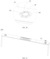
- the first anti-loosening portion 32 includes a plurality of grooves 70 arranged at intervals along a top peripheral edge of the pole body 24.
- the second anti-loosening portion 34 includes a plurality of protrusions 72 arranged at intervals circumferential along the hole wall of the second through hole 28. Each of the plurality of protrusions 72 extends towards the pole body 24in the radial direction of the pole body 24.
- the anti-loosening structure 18 may be formed into a ratchet structure to prevent the insulator 16 from loosening.
- the number of protrusions 72 may be smaller than the number of grooves 70 in order to allow the insulator 16 to be tightened more smoothly.
- two protrusions 72 and six grooves 70 is provided in FIG. 14 .
- the two protrusions 72 are arranged in a radial direction of the second through hole 28, and the six grooves 70 are divided into three groups.
- the three groups of grooves 70 are evenly arranged circumferentially around the pole body 24, and the two grooves 70 in each of the three groups are arranged in the radial direction of the pole body 24.
- the pole 14 can be disassembled from the insulator 16 by rotating the insulator 16 in the loosening direction (such as the counterclockwise direction). In the embodiments of the present disclosure, the pole 14 can be disassembled, which reduces scrap cost in the manufacturing process, allowing defective products to be easily recycled and classified and realizing high anti-loosening performance.
- the first anti-loosening portion 32 may include the protrusion 72
- the second anti-loosening portion 34 may include the groove 70.
- the protrusion 72 extends away from the pole body 24 in the radial direction of the pole body 24.
- the first anti-loosening portion 32 includes one of an engagement groove 74 and an elastic sheet 76.
- the second anti-loosening portion 34 includes the other one of the engagement groove 74 and the elastic sheet 76.
- the elastic sheet 76 is at least partially located in the engagement groove 74 to prevent the insulator 16 from loosening.
- the insulator 16 can be prevented from loosening through the engagement between the engagement groove 74 and the elastic sheet 76, and thus has a high anti-loosening performance.
- the anti-loosing structure 18 may be formed as a ratcheting elastic-sheet anti-loosing structure.
- the first anti-loosing portion 32 includes a plurality of engagement grooves 74 arranged at intervals around the pole body 24 circumferentially.
- the second anti-loosing portion 34 includes a plurality of elastic sheets 76
- the insulator 16 includes a plastic member body 78 and a plastic member flange 80.
- the plastic member flange 80 is connected to an upper end of the plastic member body 78 and has a plurality of third through holes 82 arranged in a circumferential direction of the insulator 16.
- Each of the plurality of third through holes 82 has an elastic sheet 76 at an inner wall of the third through hole 82.
- the elastic sheet 76 includes an engagement portion 84 extending out of the third through hole 82.
- the engagement groove 74 has a first side surface 86 and a second side surface 88 opposite to each other.
- the first side surface 86 and the second side surface 88 are sequentially arranged in the clockwise direction.
- the second side surface 88 and the first side surface 86 are sequentially arranged in the loosening direction of the insulator 16.
- an inclination angle of the first side surface 86 relative to a vertical plane is smaller than an inclination angle of the second side surface 88 relative to the vertical plane. Therefore, resistance to a clockwise rotation of the insulator 16 is smaller than resistance to a counterclockwise rotation of the insulator 16.
- the cover plate 12 has a first surface 36 and a second surface 38 opposite to each other.
- the first through hole 20 penetrates the first surface 36 and the second surface 38.
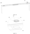
- the first anti-loosing portion 32 includes an edge portion 89 of the cover plate 12 surrounding the first through hole 20.
- the insulator 16 has a third surface 90 and a fourth surface 92 opposite to each other.
- the fourth surface 92 is connected to the first surface 36.
- the second anti-loosing portion 34 includes a hook 94 connected to the fourth surface 92, and a hooking portion 96 of the hook 94 hooks the edge portion 89 to prevent the insulator 16 from loosening.
- the insulator 16 can be prevented from loosening by hooking the hook 94 to the edge portion 89, and thus high anti-loosening performance can be realized. Meanwhile, metal debris can be avoided from being generated due to scratching between the insulator 16 and the cover plate 12, thus an internal short-circuit can be avoided.
- the first surface 36 is an upper surface of the cover plate 12, and the second surface 38 is a lower surface of the cover plate 12.
- the third surface 90 is an upper surface of the insulator 16, and the fourth surface 92 is a lower surface of the insulator 16.
- the first surface 36 and the fourth surface 92 faces towards each other and abut with each other.
- the hook 94 is provided at the fourth surface 92.
- the hooking portion 96 of the hook 94 hooks the edge portion 89 when the insulator 16 is mounted in place.
- the insulator 16 rotates in the loosening direction, the insulator 16 tends to move upwards in the axial direction of the pole body 24.
- the hooking portion 96 of the hook 94 By hooking the hooking portion 96 of the hook 94 to the edge portion 89, the insulator 16 can be blocked from moving upwards, thereby preventing the insulator 16 from loosening.
- the insulator 16 moves downwards.
- a lower end of the hook 94 moves into the first through hole 20 and slides along the hole wall of the first through hole 20.
- the hook 94 is deformed towards a center of the first through hole 20 to a certain extent.
- the hooking portion 96 of the hook 94 protrudes from the first through hole 20, and the hook 94 recovers from deformation. At this time, the hooking portion 96 hooks the edge portion 89 to prevent the insulator 16 from loosening.
- a plurality of hooks 94 is arranged at intervals in the circumferential direction of the insulator 16 to further enhance the anti-loosening effect.
- the insulator 16 is of a cylindrical or polygon prism shape.
- the insulator 16 may be adapted to different fastening tools.
- the insulator 16 is of a cylindrical shape.
- the insulator 16 has a fastening hole 98 at the upper surface of the insulator 16, into which the fastening tool may be inserted to rotate the insulator 16.
- the insulator 16 is of a hexagonal prism shape, which allows the fastening tool to be universal, and thus the insulator 16 has good structural strength. It should be understood that, in other embodiments, the insulator 16 is not limited to a hexagonal prism shape, and may also be of other polygonal prism shapes, such as a triangular prism shape, a quadrangular prism shape.
- the negative pole may further be formed through turning a copper-aluminum composite plate.
- the negative pole process has few steps and is easily controlled.
- An energy storage device includes a battery cell.
- the battery cell includes the end cover assembly 100 according to any one of the embodiments described above.
- the insulator 16 and the pole body 24 of the pole 16 are connected to the first thread 26 through the second thread 30. Therefore, without an injection molding overmolding process, a movement of the pole 14 towards an interior of a battery can be avoided. In addition, reliability of a connection between the insulator 16 and the pole body 24 of the pole 14 can be ensured by the anti-loosening structure 18.
- An electric apparatus includes the energy storage device as described above, and the energy storage device is configured to supply power to the electric apparatus.
- the electric apparatus may include and not limited to a new energy vehicle, an unmanned aerial vehicle, an energy storage container, and the like.
Landscapes
- Chemical & Material Sciences (AREA)
- Chemical Kinetics & Catalysis (AREA)
- Electrochemistry (AREA)
- General Chemical & Material Sciences (AREA)
- Engineering & Computer Science (AREA)
- Manufacturing & Machinery (AREA)
- Connection Of Batteries Or Terminals (AREA)
- Battery Mounting, Suspending (AREA)
Applications Claiming Priority (1)
| Application Number | Priority Date | Filing Date | Title |
|---|---|---|---|
| CN202310673750.4A CN116404326B (zh) | 2023-06-08 | 2023-06-08 | 端盖组件、储能装置和用电设备 |
Publications (2)
| Publication Number | Publication Date |
|---|---|
| EP4475293A2 true EP4475293A2 (fr) | 2024-12-11 |
| EP4475293A3 EP4475293A3 (fr) | 2025-01-01 |
Family
ID=87014621
Family Applications (1)
| Application Number | Title | Priority Date | Filing Date |
|---|---|---|---|
| EP24170473.3A Pending EP4475293A3 (fr) | 2023-06-08 | 2024-04-16 | Ensemble couvercle d'extrémité, dispositif de stockage d'énergie et appareil électrique |
Country Status (4)
| Country | Link |
|---|---|
| US (1) | US12107301B1 (fr) |
| EP (1) | EP4475293A3 (fr) |
| CN (1) | CN116404326B (fr) |
| WO (1) | WO2024250712A1 (fr) |
Families Citing this family (2)
| Publication number | Priority date | Publication date | Assignee | Title |
|---|---|---|---|---|
| CN116404326B (zh) * | 2023-06-08 | 2023-09-05 | 深圳海辰储能控制技术有限公司 | 端盖组件、储能装置和用电设备 |
| CN116780064A (zh) * | 2023-07-14 | 2023-09-19 | 宁夏宝丰昱能科技有限公司 | 一种盖板及电池 |
Citations (1)
| Publication number | Priority date | Publication date | Assignee | Title |
|---|---|---|---|---|
| US20120052370A1 (en) * | 2010-08-31 | 2012-03-01 | Jong-Seok Moon | Rechargeable battery |
Family Cites Families (15)
| Publication number | Priority date | Publication date | Assignee | Title |
|---|---|---|---|---|
| KR19980043346U (ko) * | 1996-12-24 | 1998-09-25 | 김종진 | 풀림방지용 와셔부재 |
| CN102299273A (zh) | 2010-06-28 | 2011-12-28 | 黎永康 | 动力锂电池顶盖电极柱密封连接和防爆装置及其制造方法 |
| WO2014042135A1 (fr) * | 2012-09-13 | 2014-03-20 | 株式会社 豊田自動織機 | Dispositif de stockage de puissance |
| CN107017361A (zh) * | 2017-05-24 | 2017-08-04 | 深圳市长盈精密技术股份有限公司 | 动力电池盖板及其动力电池 |
| CN113451713B (zh) * | 2017-08-30 | 2024-03-19 | 宁德时代新能源科技股份有限公司 | 二次电池以及电池模组 |
| US10763466B2 (en) * | 2018-03-09 | 2020-09-01 | Contemporary Amperex Technology Co., Limited | Top cap assembly of a secondary battery, and secondary battery |
| EP3943343B1 (fr) * | 2020-07-23 | 2025-10-29 | Volvo Car Corporation | Procédé d'assemblage d'une boîte de fusibles sur une batterie de véhicule |
| CN215911482U (zh) * | 2021-08-31 | 2022-02-25 | 蜂巢能源科技有限公司 | 电池盖及具有其的电池模组 |
| CN216120657U (zh) * | 2021-10-18 | 2022-03-22 | 厦门海辰新能源科技有限公司 | 顶盖组件及二次电池 |
| CN216120668U (zh) * | 2021-10-18 | 2022-03-22 | 厦门海辰新能源科技有限公司 | 二次电池的顶盖板、顶盖组件及二次电池 |
| CN114447481B (zh) * | 2022-01-10 | 2025-11-11 | 欣旺达动力科技股份有限公司 | 顶盖组件、单体电池及电池包 |
| CN217641564U (zh) | 2022-05-20 | 2022-10-21 | 格力钛新能源股份有限公司 | 一种盖板结构及锂电池 |
| CN218648105U (zh) | 2022-06-27 | 2023-03-17 | 郑州市佛山铝业有限公司 | 一种锂电池盖板极柱机构 |
| CN115207532A (zh) * | 2022-08-03 | 2022-10-18 | 中创新航科技股份有限公司 | 电池盖板组件、电池及电池盖板组件的制作方法 |
| CN116404326B (zh) * | 2023-06-08 | 2023-09-05 | 深圳海辰储能控制技术有限公司 | 端盖组件、储能装置和用电设备 |
-
2023
- 2023-06-08 CN CN202310673750.4A patent/CN116404326B/zh active Active
-
2024
- 2024-01-29 WO PCT/CN2024/074390 patent/WO2024250712A1/fr not_active Ceased
- 2024-03-20 US US18/610,274 patent/US12107301B1/en active Active
- 2024-04-16 EP EP24170473.3A patent/EP4475293A3/fr active Pending
Patent Citations (1)
| Publication number | Priority date | Publication date | Assignee | Title |
|---|---|---|---|---|
| US20120052370A1 (en) * | 2010-08-31 | 2012-03-01 | Jong-Seok Moon | Rechargeable battery |
Also Published As
| Publication number | Publication date |
|---|---|
| CN116404326A (zh) | 2023-07-07 |
| US12107301B1 (en) | 2024-10-01 |
| CN116404326B (zh) | 2023-09-05 |
| WO2024250712A1 (fr) | 2024-12-12 |
| EP4475293A3 (fr) | 2025-01-01 |
Similar Documents
| Publication | Publication Date | Title |
|---|---|---|
| EP4475293A2 (fr) | Ensemble couvercle d'extrémité, dispositif de stockage d'énergie et appareil électrique | |
| EP2382679B1 (fr) | Module de batterie comportant des cellules électrochimiques avec des bornes formées de façon solidaire | |
| US8945740B2 (en) | Vent for electrochemical cell | |
| EP3201035B1 (fr) | Support pour ensemble de barres omnibus | |
| JP5318839B2 (ja) | バッテリ | |
| US8568915B2 (en) | Battery with integrally formed terminal | |
| EP2347461B1 (fr) | Collecteur de courant pour une cellule électrochimique | |
| EP2475023B1 (fr) | Batterie et bloc-batterie l'utilisant | |
| EP2050152B1 (fr) | Batterie avec borne formée de manière intégrée | |
| JP2009080963A (ja) | 端子間接続構造 | |
| EP3726605A1 (fr) | Batterie secondaire au lithium-ion cylindrique | |
| US20240162536A1 (en) | Battery top cover assembly | |
| EP1953848B1 (fr) | Capuchon de fixation de type soudure et module cellulaire équipé de celui-ci | |
| US20240128560A1 (en) | Power battery top cover structure | |
| WO2018013404A1 (fr) | Bornes d'une cellule électrochimique | |
| US20170125783A1 (en) | Electricity storage device | |
| CN220021522U (zh) | 极芯组件、电池单体、电池包及用电装置 | |
| CN116072942B (zh) | 密封组件、燃料电池系统和车辆 | |
| JP6131815B2 (ja) | 蓄電装置 | |
| CN223680301U (zh) | 一种电池装置、储能设备及用电设备 | |
| CN220021520U (zh) | 电池单体、电池包及用电装置 | |
| EP4489213A2 (fr) | Terminal pour dispositif de stockage d'électricité et dispositif de stockage d'électricité | |
| KR100599617B1 (ko) | 이차전지 및 이차전지 모듈 | |
| CN121885876A (zh) | 电池单体及其制备方法、电池装置、用电装置、储能装置 |
Legal Events
| Date | Code | Title | Description |
|---|---|---|---|
| PUAI | Public reference made under article 153(3) epc to a published international application that has entered the european phase |
Free format text: ORIGINAL CODE: 0009012 |
|
| STAA | Information on the status of an ep patent application or granted ep patent |
Free format text: STATUS: THE APPLICATION HAS BEEN PUBLISHED |
|
| PUAL | Search report despatched |
Free format text: ORIGINAL CODE: 0009013 |
|
| AK | Designated contracting states |
Kind code of ref document: A2 Designated state(s): AL AT BE BG CH CY CZ DE DK EE ES FI FR GB GR HR HU IE IS IT LI LT LU LV MC ME MK MT NL NO PL PT RO RS SE SI SK SM TR |
|
| AK | Designated contracting states |
Kind code of ref document: A3 Designated state(s): AL AT BE BG CH CY CZ DE DK EE ES FI FR GB GR HR HU IE IS IT LI LT LU LV MC ME MK MT NL NO PL PT RO RS SE SI SK SM TR |
|
| RIC1 | Information provided on ipc code assigned before grant |
Ipc: H01M 50/593 20210101ALI20241127BHEP Ipc: H01M 50/567 20210101ALI20241127BHEP Ipc: H01M 50/15 20210101ALI20241127BHEP Ipc: H01M 50/147 20210101AFI20241127BHEP |
|
| RAP1 | Party data changed (applicant data changed or rights of an application transferred) |
Owner name: HITHIUM TECH HK LIMITED |
|
| STAA | Information on the status of an ep patent application or granted ep patent |
Free format text: STATUS: REQUEST FOR EXAMINATION WAS MADE |
|
| 17P | Request for examination filed |
Effective date: 20250630 |
|
| STAA | Information on the status of an ep patent application or granted ep patent |
Free format text: STATUS: EXAMINATION IS IN PROGRESS |
|
| 17Q | First examination report despatched |
Effective date: 20251211 |