EP4474894A2 - Intelligentes kleidungsstück - Google Patents
Intelligentes kleidungsstück Download PDFInfo
- Publication number
- EP4474894A2 EP4474894A2 EP24209291.4A EP24209291A EP4474894A2 EP 4474894 A2 EP4474894 A2 EP 4474894A2 EP 24209291 A EP24209291 A EP 24209291A EP 4474894 A2 EP4474894 A2 EP 4474894A2
- Authority
- EP
- European Patent Office
- Prior art keywords
- garment
- smart garment
- user terminal
- image
- smart
- Prior art date
- Legal status (The legal status is an assumption and is not a legal conclusion. Google has not performed a legal analysis and makes no representation as to the accuracy of the status listed.)
- Pending
Links
Images


Classifications
-
- A—HUMAN NECESSITIES
- A41—WEARING APPAREL
- A41D—OUTERWEAR; PROTECTIVE GARMENTS; ACCESSORIES
- A41D1/00—Garments
- A41D1/002—Garments adapted to accommodate electronic equipment
-
- A—HUMAN NECESSITIES
- A41—WEARING APPAREL
- A41D—OUTERWEAR; PROTECTIVE GARMENTS; ACCESSORIES
- A41D15/00—Convertible garments
-
- D—TEXTILES; PAPER
- D03—WEAVING
- D03D—WOVEN FABRICS; METHODS OF WEAVING; LOOMS
- D03D1/00—Woven fabrics designed to make specified articles
- D03D1/0088—Fabrics having an electronic function
-
- D—TEXTILES; PAPER
- D03—WEAVING
- D03D—WOVEN FABRICS; METHODS OF WEAVING; LOOMS
- D03D15/00—Woven fabrics characterised by the material, structure or properties of the fibres, filaments, yarns, threads or other warp or weft elements used
- D03D15/50—Woven fabrics characterised by the material, structure or properties of the fibres, filaments, yarns, threads or other warp or weft elements used characterised by the properties of the yarns or threads
- D03D15/54—Woven fabrics characterised by the material, structure or properties of the fibres, filaments, yarns, threads or other warp or weft elements used characterised by the properties of the yarns or threads coloured
-
- D—TEXTILES; PAPER
- D03—WEAVING
- D03D—WOVEN FABRICS; METHODS OF WEAVING; LOOMS
- D03D15/00—Woven fabrics characterised by the material, structure or properties of the fibres, filaments, yarns, threads or other warp or weft elements used
- D03D15/50—Woven fabrics characterised by the material, structure or properties of the fibres, filaments, yarns, threads or other warp or weft elements used characterised by the properties of the yarns or threads
- D03D15/547—Woven fabrics characterised by the material, structure or properties of the fibres, filaments, yarns, threads or other warp or weft elements used characterised by the properties of the yarns or threads with optical functions other than colour, e.g. comprising light-emitting fibres
-
- D—TEXTILES; PAPER
- D03—WEAVING
- D03D—WOVEN FABRICS; METHODS OF WEAVING; LOOMS
- D03D15/00—Woven fabrics characterised by the material, structure or properties of the fibres, filaments, yarns, threads or other warp or weft elements used
- D03D15/60—Woven fabrics characterised by the material, structure or properties of the fibres, filaments, yarns, threads or other warp or weft elements used characterised by the warp or weft elements other than yarns or threads
- D03D15/67—Metal wires
-
- G—PHYSICS
- G02—OPTICS
- G02F—OPTICAL DEVICES OR ARRANGEMENTS FOR THE CONTROL OF LIGHT BY MODIFICATION OF THE OPTICAL PROPERTIES OF THE MEDIA OF THE ELEMENTS INVOLVED THEREIN; NON-LINEAR OPTICS; FREQUENCY-CHANGING OF LIGHT; OPTICAL LOGIC ELEMENTS; OPTICAL ANALOGUE/DIGITAL CONVERTERS
- G02F1/00—Devices or arrangements for the control of the intensity, colour, phase, polarisation or direction of light arriving from an independent light source, e.g. switching, gating or modulating; Non-linear optics
- G02F1/01—Devices or arrangements for the control of the intensity, colour, phase, polarisation or direction of light arriving from an independent light source, e.g. switching, gating or modulating; Non-linear optics for the control of the intensity, phase, polarisation or colour
- G02F1/13—Devices or arrangements for the control of the intensity, colour, phase, polarisation or direction of light arriving from an independent light source, e.g. switching, gating or modulating; Non-linear optics for the control of the intensity, phase, polarisation or colour based on liquid crystals, e.g. single liquid crystal display cells
- G02F1/1313—Devices or arrangements for the control of the intensity, colour, phase, polarisation or direction of light arriving from an independent light source, e.g. switching, gating or modulating; Non-linear optics for the control of the intensity, phase, polarisation or colour based on liquid crystals, e.g. single liquid crystal display cells specially adapted for a particular application
-
- G—PHYSICS
- G02—OPTICS
- G02F—OPTICAL DEVICES OR ARRANGEMENTS FOR THE CONTROL OF LIGHT BY MODIFICATION OF THE OPTICAL PROPERTIES OF THE MEDIA OF THE ELEMENTS INVOLVED THEREIN; NON-LINEAR OPTICS; FREQUENCY-CHANGING OF LIGHT; OPTICAL LOGIC ELEMENTS; OPTICAL ANALOGUE/DIGITAL CONVERTERS
- G02F1/00—Devices or arrangements for the control of the intensity, colour, phase, polarisation or direction of light arriving from an independent light source, e.g. switching, gating or modulating; Non-linear optics
- G02F1/01—Devices or arrangements for the control of the intensity, colour, phase, polarisation or direction of light arriving from an independent light source, e.g. switching, gating or modulating; Non-linear optics for the control of the intensity, phase, polarisation or colour
- G02F1/13—Devices or arrangements for the control of the intensity, colour, phase, polarisation or direction of light arriving from an independent light source, e.g. switching, gating or modulating; Non-linear optics for the control of the intensity, phase, polarisation or colour based on liquid crystals, e.g. single liquid crystal display cells
- G02F1/133—Constructional arrangements; Operation of liquid crystal cells; Circuit arrangements
- G02F1/1333—Constructional arrangements; Manufacturing methods
- G02F1/1334—Constructional arrangements; Manufacturing methods based on polymer dispersed liquid crystals, e.g. microencapsulated liquid crystals
-
- G—PHYSICS
- G02—OPTICS
- G02F—OPTICAL DEVICES OR ARRANGEMENTS FOR THE CONTROL OF LIGHT BY MODIFICATION OF THE OPTICAL PROPERTIES OF THE MEDIA OF THE ELEMENTS INVOLVED THEREIN; NON-LINEAR OPTICS; FREQUENCY-CHANGING OF LIGHT; OPTICAL LOGIC ELEMENTS; OPTICAL ANALOGUE/DIGITAL CONVERTERS
- G02F1/00—Devices or arrangements for the control of the intensity, colour, phase, polarisation or direction of light arriving from an independent light source, e.g. switching, gating or modulating; Non-linear optics
- G02F1/01—Devices or arrangements for the control of the intensity, colour, phase, polarisation or direction of light arriving from an independent light source, e.g. switching, gating or modulating; Non-linear optics for the control of the intensity, phase, polarisation or colour
- G02F1/13—Devices or arrangements for the control of the intensity, colour, phase, polarisation or direction of light arriving from an independent light source, e.g. switching, gating or modulating; Non-linear optics for the control of the intensity, phase, polarisation or colour based on liquid crystals, e.g. single liquid crystal display cells
- G02F1/133—Constructional arrangements; Operation of liquid crystal cells; Circuit arrangements
- G02F1/1333—Constructional arrangements; Manufacturing methods
- G02F1/1343—Electrodes
- G02F1/134309—Electrodes characterised by their geometrical arrangement
-
- G—PHYSICS
- G02—OPTICS
- G02F—OPTICAL DEVICES OR ARRANGEMENTS FOR THE CONTROL OF LIGHT BY MODIFICATION OF THE OPTICAL PROPERTIES OF THE MEDIA OF THE ELEMENTS INVOLVED THEREIN; NON-LINEAR OPTICS; FREQUENCY-CHANGING OF LIGHT; OPTICAL LOGIC ELEMENTS; OPTICAL ANALOGUE/DIGITAL CONVERTERS
- G02F1/00—Devices or arrangements for the control of the intensity, colour, phase, polarisation or direction of light arriving from an independent light source, e.g. switching, gating or modulating; Non-linear optics
- G02F1/01—Devices or arrangements for the control of the intensity, colour, phase, polarisation or direction of light arriving from an independent light source, e.g. switching, gating or modulating; Non-linear optics for the control of the intensity, phase, polarisation or colour
- G02F1/15—Devices or arrangements for the control of the intensity, colour, phase, polarisation or direction of light arriving from an independent light source, e.g. switching, gating or modulating; Non-linear optics for the control of the intensity, phase, polarisation or colour based on an electrochromic effect
- G02F1/153—Constructional details
- G02F1/155—Electrodes
-
- G—PHYSICS
- G02—OPTICS
- G02F—OPTICAL DEVICES OR ARRANGEMENTS FOR THE CONTROL OF LIGHT BY MODIFICATION OF THE OPTICAL PROPERTIES OF THE MEDIA OF THE ELEMENTS INVOLVED THEREIN; NON-LINEAR OPTICS; FREQUENCY-CHANGING OF LIGHT; OPTICAL LOGIC ELEMENTS; OPTICAL ANALOGUE/DIGITAL CONVERTERS
- G02F1/00—Devices or arrangements for the control of the intensity, colour, phase, polarisation or direction of light arriving from an independent light source, e.g. switching, gating or modulating; Non-linear optics
- G02F1/01—Devices or arrangements for the control of the intensity, colour, phase, polarisation or direction of light arriving from an independent light source, e.g. switching, gating or modulating; Non-linear optics for the control of the intensity, phase, polarisation or colour
- G02F1/165—Devices or arrangements for the control of the intensity, colour, phase, polarisation or direction of light arriving from an independent light source, e.g. switching, gating or modulating; Non-linear optics for the control of the intensity, phase, polarisation or colour based on translational movement of particles in a fluid under the influence of an applied field
- G02F1/166—Devices or arrangements for the control of the intensity, colour, phase, polarisation or direction of light arriving from an independent light source, e.g. switching, gating or modulating; Non-linear optics for the control of the intensity, phase, polarisation or colour based on translational movement of particles in a fluid under the influence of an applied field characterised by the electro-optical or magneto-optical effect
- G02F1/167—Devices or arrangements for the control of the intensity, colour, phase, polarisation or direction of light arriving from an independent light source, e.g. switching, gating or modulating; Non-linear optics for the control of the intensity, phase, polarisation or colour based on translational movement of particles in a fluid under the influence of an applied field characterised by the electro-optical or magneto-optical effect by electrophoresis
-
- G—PHYSICS
- G02—OPTICS
- G02F—OPTICAL DEVICES OR ARRANGEMENTS FOR THE CONTROL OF LIGHT BY MODIFICATION OF THE OPTICAL PROPERTIES OF THE MEDIA OF THE ELEMENTS INVOLVED THEREIN; NON-LINEAR OPTICS; FREQUENCY-CHANGING OF LIGHT; OPTICAL LOGIC ELEMENTS; OPTICAL ANALOGUE/DIGITAL CONVERTERS
- G02F1/00—Devices or arrangements for the control of the intensity, colour, phase, polarisation or direction of light arriving from an independent light source, e.g. switching, gating or modulating; Non-linear optics
- G02F1/01—Devices or arrangements for the control of the intensity, colour, phase, polarisation or direction of light arriving from an independent light source, e.g. switching, gating or modulating; Non-linear optics for the control of the intensity, phase, polarisation or colour
- G02F1/165—Devices or arrangements for the control of the intensity, colour, phase, polarisation or direction of light arriving from an independent light source, e.g. switching, gating or modulating; Non-linear optics for the control of the intensity, phase, polarisation or colour based on translational movement of particles in a fluid under the influence of an applied field
- G02F1/1675—Constructional details
- G02F1/16757—Microcapsules
-
- G—PHYSICS
- G02—OPTICS
- G02F—OPTICAL DEVICES OR ARRANGEMENTS FOR THE CONTROL OF LIGHT BY MODIFICATION OF THE OPTICAL PROPERTIES OF THE MEDIA OF THE ELEMENTS INVOLVED THEREIN; NON-LINEAR OPTICS; FREQUENCY-CHANGING OF LIGHT; OPTICAL LOGIC ELEMENTS; OPTICAL ANALOGUE/DIGITAL CONVERTERS
- G02F1/00—Devices or arrangements for the control of the intensity, colour, phase, polarisation or direction of light arriving from an independent light source, e.g. switching, gating or modulating; Non-linear optics
- G02F1/01—Devices or arrangements for the control of the intensity, colour, phase, polarisation or direction of light arriving from an independent light source, e.g. switching, gating or modulating; Non-linear optics for the control of the intensity, phase, polarisation or colour
- G02F1/165—Devices or arrangements for the control of the intensity, colour, phase, polarisation or direction of light arriving from an independent light source, e.g. switching, gating or modulating; Non-linear optics for the control of the intensity, phase, polarisation or colour based on translational movement of particles in a fluid under the influence of an applied field
- G02F1/1675—Constructional details
- G02F1/1676—Electrodes
-
- G—PHYSICS
- G06—COMPUTING OR CALCULATING; COUNTING
- G06F—ELECTRIC DIGITAL DATA PROCESSING
- G06F3/00—Input arrangements for transferring data to be processed into a form capable of being handled by the computer; Output arrangements for transferring data from processing unit to output unit, e.g. interface arrangements
- G06F3/01—Input arrangements or combined input and output arrangements for interaction between user and computer
- G06F3/048—Interaction techniques based on graphical user interfaces [GUI]
- G06F3/0481—Interaction techniques based on graphical user interfaces [GUI] based on specific properties of the displayed interaction object or a metaphor-based environment, e.g. interaction with desktop elements like windows or icons, or assisted by a cursor's changing behaviour or appearance
- G06F3/0482—Interaction with lists of selectable items, e.g. menus
-
- G—PHYSICS
- G06—COMPUTING OR CALCULATING; COUNTING
- G06F—ELECTRIC DIGITAL DATA PROCESSING
- G06F3/00—Input arrangements for transferring data to be processed into a form capable of being handled by the computer; Output arrangements for transferring data from processing unit to output unit, e.g. interface arrangements
- G06F3/01—Input arrangements or combined input and output arrangements for interaction between user and computer
- G06F3/048—Interaction techniques based on graphical user interfaces [GUI]
- G06F3/0484—Interaction techniques based on graphical user interfaces [GUI] for the control of specific functions or operations, e.g. selecting or manipulating an object, an image or a displayed text element, setting a parameter value or selecting a range
- G06F3/04842—Selection of displayed objects or displayed text elements
-
- G—PHYSICS
- G06—COMPUTING OR CALCULATING; COUNTING
- G06Q—INFORMATION AND COMMUNICATION TECHNOLOGY [ICT] SPECIALLY ADAPTED FOR ADMINISTRATIVE, COMMERCIAL, FINANCIAL, MANAGERIAL OR SUPERVISORY PURPOSES; SYSTEMS OR METHODS SPECIALLY ADAPTED FOR ADMINISTRATIVE, COMMERCIAL, FINANCIAL, MANAGERIAL OR SUPERVISORY PURPOSES, NOT OTHERWISE PROVIDED FOR
- G06Q30/00—Commerce
- G06Q30/02—Marketing; Price estimation or determination; Fundraising
- G06Q30/0241—Advertisements
- G06Q30/0251—Targeted advertisements
-
- G—PHYSICS
- G06—COMPUTING OR CALCULATING; COUNTING
- G06Q—INFORMATION AND COMMUNICATION TECHNOLOGY [ICT] SPECIALLY ADAPTED FOR ADMINISTRATIVE, COMMERCIAL, FINANCIAL, MANAGERIAL OR SUPERVISORY PURPOSES; SYSTEMS OR METHODS SPECIALLY ADAPTED FOR ADMINISTRATIVE, COMMERCIAL, FINANCIAL, MANAGERIAL OR SUPERVISORY PURPOSES, NOT OTHERWISE PROVIDED FOR
- G06Q30/00—Commerce
- G06Q30/06—Buying, selling or leasing transactions
- G06Q30/0601—Electronic shopping [e-shopping]
- G06Q30/0621—Electronic shopping [e-shopping] by configuring or customising goods or services
-
- G—PHYSICS
- G06—COMPUTING OR CALCULATING; COUNTING
- G06Q—INFORMATION AND COMMUNICATION TECHNOLOGY [ICT] SPECIALLY ADAPTED FOR ADMINISTRATIVE, COMMERCIAL, FINANCIAL, MANAGERIAL OR SUPERVISORY PURPOSES; SYSTEMS OR METHODS SPECIALLY ADAPTED FOR ADMINISTRATIVE, COMMERCIAL, FINANCIAL, MANAGERIAL OR SUPERVISORY PURPOSES, NOT OTHERWISE PROVIDED FOR
- G06Q50/00—Information and communication technology [ICT] specially adapted for implementation of business processes of specific business sectors, e.g. utilities or tourism
- G06Q50/04—Manufacturing
-
- G—PHYSICS
- G09—EDUCATION; CRYPTOGRAPHY; DISPLAY; ADVERTISING; SEALS
- G09G—ARRANGEMENTS OR CIRCUITS FOR CONTROL OF INDICATING DEVICES USING STATIC MEANS TO PRESENT VARIABLE INFORMATION
- G09G5/00—Control arrangements or circuits for visual indicators common to cathode-ray tube indicators and other visual indicators
- G09G5/003—Details of a display terminal, the details relating to the control arrangement of the display terminal and to the interfaces thereto
- G09G5/006—Details of the interface to the display terminal
-
- H—ELECTRICITY
- H04—ELECTRIC COMMUNICATION TECHNIQUE
- H04L—TRANSMISSION OF DIGITAL INFORMATION, e.g. TELEGRAPHIC COMMUNICATION
- H04L67/00—Network arrangements or protocols for supporting network services or applications
- H04L67/01—Protocols
- H04L67/12—Protocols specially adapted for proprietary or special-purpose networking environments, e.g. medical networks, sensor networks, networks in vehicles or remote metering networks
-
- H—ELECTRICITY
- H04—ELECTRIC COMMUNICATION TECHNIQUE
- H04N—PICTORIAL COMMUNICATION, e.g. TELEVISION
- H04N21/00—Selective content distribution, e.g. interactive television or video on demand [VOD]
- H04N21/40—Client devices specifically adapted for the reception of or interaction with content, e.g. set-top-box [STB]; Operations thereof
- H04N21/41—Structure of client; Structure of client peripherals
- H04N21/422—Input-only peripherals, i.e. input devices connected to specially adapted client devices, e.g. global positioning system [GPS]
- H04N21/42204—User interfaces specially adapted for controlling a client device through a remote control device; Remote control devices therefor
-
- H—ELECTRICITY
- H04—ELECTRIC COMMUNICATION TECHNIQUE
- H04N—PICTORIAL COMMUNICATION, e.g. TELEVISION
- H04N5/00—Details of television systems
- H04N5/44—Receiver circuitry for the reception of television signals according to analogue transmission standards
-
- A—HUMAN NECESSITIES
- A41—WEARING APPAREL
- A41D—OUTERWEAR; PROTECTIVE GARMENTS; ACCESSORIES
- A41D27/00—Details of garments or of their making
- A41D27/08—Trimmings; Ornaments
-
- A—HUMAN NECESSITIES
- A41—WEARING APPAREL
- A41D—OUTERWEAR; PROTECTIVE GARMENTS; ACCESSORIES
- A41D31/00—Materials specially adapted for outerwear
- A41D31/0005—Materials specially adapted for outerwear made from a plurality of interconnected elements
-
- D—TEXTILES; PAPER
- D01—NATURAL OR MAN-MADE THREADS OR FIBRES; SPINNING
- D01D—MECHANICAL METHODS OR APPARATUS IN THE MANUFACTURE OF ARTIFICIAL FILAMENTS, THREADS, FIBRES, BRISTLES OR RIBBONS
- D01D5/00—Formation of filaments, threads, or the like
- D01D5/28—Formation of filaments, threads, or the like while mixing different spinning solutions or melts during the spinning operation; Spinnerette packs therefor
- D01D5/30—Conjugate filaments; Spinnerette packs therefor
-
- D—TEXTILES; PAPER
- D01—NATURAL OR MAN-MADE THREADS OR FIBRES; SPINNING
- D01F—CHEMICAL FEATURES IN THE MANUFACTURE OF ARTIFICIAL FILAMENTS, THREADS, FIBRES, BRISTLES OR RIBBONS; APPARATUS SPECIALLY ADAPTED FOR THE MANUFACTURE OF CARBON FILAMENTS
- D01F8/00—Conjugated, i.e. bi- or multicomponent, artificial filaments or the like; Manufacture thereof
-
- D—TEXTILES; PAPER
- D10—INDEXING SCHEME ASSOCIATED WITH SUBLASSES OF SECTION D, RELATING TO TEXTILES
- D10B—INDEXING SCHEME ASSOCIATED WITH SUBLASSES OF SECTION D, RELATING TO TEXTILES
- D10B2401/00—Physical properties
- D10B2401/18—Physical properties including electronic components
-
- D—TEXTILES; PAPER
- D10—INDEXING SCHEME ASSOCIATED WITH SUBLASSES OF SECTION D, RELATING TO TEXTILES
- D10B—INDEXING SCHEME ASSOCIATED WITH SUBLASSES OF SECTION D, RELATING TO TEXTILES
- D10B2401/00—Physical properties
- D10B2401/20—Physical properties optical
-
- G—PHYSICS
- G02—OPTICS
- G02F—OPTICAL DEVICES OR ARRANGEMENTS FOR THE CONTROL OF LIGHT BY MODIFICATION OF THE OPTICAL PROPERTIES OF THE MEDIA OF THE ELEMENTS INVOLVED THEREIN; NON-LINEAR OPTICS; FREQUENCY-CHANGING OF LIGHT; OPTICAL LOGIC ELEMENTS; OPTICAL ANALOGUE/DIGITAL CONVERTERS
- G02F1/00—Devices or arrangements for the control of the intensity, colour, phase, polarisation or direction of light arriving from an independent light source, e.g. switching, gating or modulating; Non-linear optics
- G02F1/01—Devices or arrangements for the control of the intensity, colour, phase, polarisation or direction of light arriving from an independent light source, e.g. switching, gating or modulating; Non-linear optics for the control of the intensity, phase, polarisation or colour
- G02F1/15—Devices or arrangements for the control of the intensity, colour, phase, polarisation or direction of light arriving from an independent light source, e.g. switching, gating or modulating; Non-linear optics for the control of the intensity, phase, polarisation or colour based on an electrochromic effect
- G02F1/153—Constructional details
- G02F1/155—Electrodes
- G02F2001/1555—Counter electrode
-
- G—PHYSICS
- G02—OPTICS
- G02F—OPTICAL DEVICES OR ARRANGEMENTS FOR THE CONTROL OF LIGHT BY MODIFICATION OF THE OPTICAL PROPERTIES OF THE MEDIA OF THE ELEMENTS INVOLVED THEREIN; NON-LINEAR OPTICS; FREQUENCY-CHANGING OF LIGHT; OPTICAL LOGIC ELEMENTS; OPTICAL ANALOGUE/DIGITAL CONVERTERS
- G02F2202/00—Materials and properties
- G02F2202/02—Materials and properties organic material
- G02F2202/022—Materials and properties organic material polymeric
-
- G—PHYSICS
- G09—EDUCATION; CRYPTOGRAPHY; DISPLAY; ADVERTISING; SEALS
- G09G—ARRANGEMENTS OR CIRCUITS FOR CONTROL OF INDICATING DEVICES USING STATIC MEANS TO PRESENT VARIABLE INFORMATION
- G09G2320/00—Control of display operating conditions
- G09G2320/04—Maintaining the quality of display appearance
- G09G2320/041—Temperature compensation
-
- G—PHYSICS
- G09—EDUCATION; CRYPTOGRAPHY; DISPLAY; ADVERTISING; SEALS
- G09G—ARRANGEMENTS OR CIRCUITS FOR CONTROL OF INDICATING DEVICES USING STATIC MEANS TO PRESENT VARIABLE INFORMATION
- G09G2360/00—Aspects of the architecture of display systems
- G09G2360/14—Detecting light within display terminals, e.g. using a single or a plurality of photosensors
- G09G2360/144—Detecting light within display terminals, e.g. using a single or a plurality of photosensors the light being ambient light
Definitions
- IoT Internet of Things
- Disclosed embodiments provide a smart garment capable of changing design, such as a color, an image, or text, which are implemented on the garment.
- disclosed embodiments provide a system including a server which provides various designs to be implemented on a smart garment and a user terminal which receives the various designs from the server and transmits the designs to the smart garment to change a design of the smart garment.
- a system includes: a smart garment provided to allow a design including a color, an image, text, and combinations thereof to be changed; a server including a design database with respect to the smart garment; a provider terminal provided to upload a design of the smart garment to the server; and a user terminal provided to download the design of the smart garment from the server and transmit a signal corresponding to the design of the smart garment to the smart garment to change the design of the smart garment.
- the smart garment may include a fabric including color-changing fibers and textile fibers, and a connection module provided to receive the signal transmitted by the user terminal.
- the color-changing fiber may include at least one of a cholesteric liquid crystal fiber, an electronic ink fiber, an electrochromic fiber, and an electroluminescent fiber.
- the user terminal may be paired with the smart garment and transmit a design selected by a user to the paired smart garment.
- the user terminal may display a garment display area provided to allow the smart garment to be displayed, a color selection area provided to allow a color of the smart garment displayed in the garment display area to be selected, an image selection area provided to allow an image, which will be implemented on the smart garment displayed in the garment display area, to be selected, and a text input area provided to allow text, which will be implemented on the smart garment displayed in the garment display area, to be input.
- a user terminal includes: a communicator configured to communicate with a server and a smart garment; a display configured to display a design of the smart garment transmitted from the server and received by the communicator; and a processor configured to transmit a signal including selected design information to the smart garment through the communicator when the design of the smart garment displayed on the display is selected.
- the display may display a search button provided to receive a command for searching for a smart garment, a garment display area in which a found smart garment is displayed when the command is input via the search button, and a pairing button provided to receive a command for pairing with a garment selected among garments displayed on the garment display area.
- the display may display the paired smart garment in the garment display area.
- the processor may search for smart garments around the user terminal and be paired with a smart garment selected by a user among the found smart garments when the command is input via the pairing button.
- the display may display the color selection area below the garment display area, display the image selection area below the color selection area, and display the text input area below the image selection area.
- the display may display an object representing that the smart garment displayed in the garment display area is paired with the user terminal.
- the display may change a color and a type of an image displayed in the color selection area and the image selection area to a color and an image which are associated with the changed smart garment, and display the changed color and image.
- the display may display at least one of an image received from the server, an image stored in the user terminal, and an object for driving a camera of the user terminal in the image selection area.
- the display may apply an image captured by the camera to the smart garment displayed in the garment display area.
- the processor may transmit the captured image to the smart garment.
- the processor may transmit the selected image to the smart garment and the display may display the selected image on the smart garment displayed in the garment display area.
- the processor may transmit the selected color to the smart garment and the display may apply the selected color to the smart garment displayed in the garment display area.
- the processor may transmit the input text to the smart garment and the display may display the input text on the smart garment displayed in the garment display area.
- the processor may generate a design, which will be implemented on the smart garment on the basis of location information or weather information, and transmit the generated design to the smart garment through the communicator.
- the processor may generate a design based on surrounding information of the user terminal and transmit the generated design to the smart garment.
- a smart garment includes: a first material including a first electrode and a second electrode; a second material including a third electrode and a fourth electrode; and a connection module including a first ground terminal configured to ground any one of the first electrode and the second electrode in response to a signal transmitted by a user terminal, a first signal terminal applying a voltage to the remaining one of the first electrode and the second electrode, a second ground terminal configured to ground any one of the third electrode and the fourth electrode, and a second signal terminal applying a voltage to the remaining one of the third electrode and the fourth electrode.
- connection module may include a communicator provided to communicate with the user terminal through wired/wireless communication.
- the cholesteric liquid crystal fiber may further include a connection portion provided to connect the cholesteric liquid crystal fibers so as to extend the cholesteric liquid crystal fiber.
- the cholesteric liquid crystal may include a pixel including at least one of a red sub-cell configured to reflect red light, a green sub-cell configured to reflect green light, and a blue sub-cell configured to reflect blue light.
- first material and the second material may include electronic ink fibers.
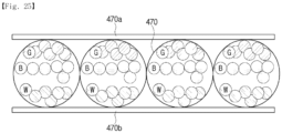
- the electronic ink fiber may include a plurality of electronic ink capsules including an electronic ink, a first electrode provided at one side of the electronic ink capsules, a second electrode provided at a side opposite the first electrode, an insulator provided between the first electrode and the second electrode, and a protective layer provided to cover the first electrode, the second electrode, and the insulator.
- the electronic ink capsule may include at least one electronic ink among a red electronic ink configured to reflect red light, a green electronic ink configured to reflect green light, and a blue electronic ink configured to reflect blue light, a black electronic ink configured to absorb light, and a white electronic ink configured to reflect light.
- first material and the second material may include electrochromic fibers.
- the electrochromic fiber may include a first electrode, a counter electrode provided outside the first electrode, an electrolyte provided outside the counter electrode, a working electrode provided outside the electrolyte, a second electrode provided outside the working electrode, and a protective layer provided to cover the second electrode.
- the counter electrode may include a first color-changing material that changes color as the first color-changing material is oxidized.
- first material and the second material may include electroluminescent fibers.
- the electroluminescent fiber may include a first electrode, a light emitter provided outside the first electrode, a second electrode provided outside the light emitter, and a protective layer provided to cover the second electrode.
- the electroluminescent fiber may include a first electrode, a light emitter provided outside the first electrode, at least three second electrodes provided outside the light emitter and provided not in contact with each other, a red color filter, a green color filter, and a blue color filter which are each provided outside a corresponding one of the at least three second electrodes, and a protective layer provided to cover the red color filter, the green color filter, and the blue color filter.
- the electroluminescent fiber may include a first electrode, a red light emitter, a green light emitter, and a blue light emitter provided outside the first electrode, a second electrode provided outside each of the red light emitter, the green light emitter, and the blue light emitter, and a protective layer provided to cover the second electrode.
- the electroluminescent fiber may include a core fiber, at least three first electrodes provided outside the core fiber and provided not in contact with each other, a red light emitter, a green light emitter, and blue light emitter each provided outside a corresponding one of the at least three first electrodes, a second electrode provided outside each of the red light emitter, the green light emitter, and the blue light emitter, and a protective layer provided to cover the second electrode.
- a method of changing a design of a smart garment includes: receiving, at a user terminal, a design of a smart garment including a color, an image, text, and combinations thereof from a server; displaying the received design on the user terminal; and when the displayed design is selected, transmitting the selected design from the user terminal to the smart garment so that a design of the smart garment is changed to the selected design.
- the method may further include: searching for a smart garment in the user terminal; displaying a found smart garment in the user terminal; and when the displayed smart garment is selected, pairing the smart garment with the user terminal in the user terminal.
- a smart garment according to the disclosed embodiments can change a design element, such as a color, an image, or text, so that a user can change a design of the smart garment to a desired design, regardless of time and place.
- a design element such as a color, an image, or text
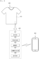
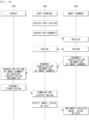
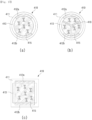
- FIG. 1 is a conceptual view of a system according to one illustrated embodiment
- FIGS. 2 and 3 are diagrams illustrating a configuration of a smart garment 400 according to one illustrated embodiment.
- the system includes the smart garment 400, a provider terminal 100 configured to upload a design implementable on the smart garment 400 to a server 200, the server 200 configured to store the design uploaded by the provider terminal 100, and a user terminal 300 configured to download the design implementable on the smart garment 400 from the server 200 and transmit the design to the smart garment 400.
- the design of the smart garment 400 refers to a color, an image, text, or a combination thereof, which is displayable on the smart garment 400.
- a provider of the smart garment 400 such as a seller or a business operator of the smart garment 400, may upload the design implementable on the smart garment 400 to the server 200 using the provider terminal 100.
- a separate design provider or purchaser may freely upload a design of the smart garment 400 to the server 200.
- the provider terminal 100 may include a computer capable of communicating with the server 200 or a mobile device such as a smart phone or a tablet personal computer (PC).
- the devices are merely examples of the provider terminal 100, and any device may be included in the range of the provider terminal 100 as long as the device is capable of communicating with the server 200.
- the provider of the smart garment 400 uploads identification information of the smart garment 400 on which the uploaded design can be implemented, for example, a product number, a trademark, a size, a material, and the like, when the design is uploaded to the server 200 so that a design that can be implemented on the smart garment 400 possessed by the purchaser can be easily retrieved.
- the server 200 stores designs of the smart garment 400 uploaded from various provider terminals 100 to build a database.
- the server 200 may classify and store designs by providers who have uploaded the designs and classify and store designs uploaded by the same provider according to the type of smart garment 400.
- a user may access the server 200 through the user terminal 300 and download the design from the server 200 after undergoing a predetermined authentication process.
- the user When the user inputs the identification information of the smart garment 400, for example, the product number, the trademark, the size, the material, and the like, through the user terminal 300 after undergoing the authentication process, the user may download a design of the smart garment 400 associated with the input identification information from the server 200 to the user terminal 300.
- the identification information of the smart garment 400 for example, the product number, the trademark, the size, the material, and the like
- the user terminal 300 may include a computer capable of communicating with the server 200 or a mobile device such as a smart phone or a tablet PC.
- the devices are merely examples of the user terminal 300, and any device may be included in the range of the user terminal 300 as long as the device is capable of communicating with the server 200.
- the user terminal may include a communicator capable of communicating with the server or the smart garment, a display configured to display a user interface for changing a design of the smart garment, and a processor configured to generate a signal including a design of the smart garment and transmit the signal to the smart garment through the communicator when the design of the smart garment displayed on the display is selected.
- the user terminal 300 may serve as the provider terminal 100 when the design of the smart garment 400 is uploaded to the server 200 through the user terminal 300, and even the provider terminal 100 may serve as the user terminal 300 when the provider terminal 100 downloads the design of the smart garment from the server 200.
- the user terminal 300 transmits design information selected by the user from the design downloaded from the server 200 or a previously stored design to the smart garment 400.
- the smart garment 400 includes a connection module 420 that may receive the design information transmitted from the user terminal 300 and change the design of the smart garment 400 based on the received information.
- the connection module 420 of the smart garment 400 when the connection module 420 of the smart garment 400 receives the signal including design information transmitted from the user terminal 300, the smart garment 400 changes a color, displays or changes text, or displays or changes a pattern according to the received signal. That is, the user may implement various designs on one smart garment 400.
- connection module 420 of the smart garment 400 will be first described in detail with reference to FIGS. 2 and 3 , and a method of changing a design of the smart garment 400 and a user interface of the user terminal for changing a design of the smart garment 400 in the system according to one disclosed embodiment will be described in detail with reference to FIGS. 4 to 16 .
- the connection module 420 may include a communicator 427 configured to perform wired/wireless communication with the user terminal 300, a processor 423 configured to generate a control signal for changing a design of the smart garment 400 according to a signal received by the communicator 427, a driver 421 configured to apply a voltage to the smart garment 400 according to the control signal generated by the processor 423, a memory 425 configured to store design information included in the signal received by the communicator 427 or information related to a current design of the smart garment 400, and a battery configured to supply power to the smart garment 400.
- a communicator 427 configured to perform wired/wireless communication with the user terminal 300
- a processor 423 configured to generate a control signal for changing a design of the smart garment 400 according to a signal received by the communicator 427
- a driver 421 configured to apply a voltage to the smart garment 400 according to the control signal generated by the processor 423
- a memory 425 configured to store design information included in the signal received by the communicator
- the communicator 427 of the connection module 420 is connected to the user terminal 300 through a communication scheme, such as a wireless local area network (LAN), Wi-Fi, Bluetooth, ZigBee, an ultra-wideband (UWB), infrared data association (IrDA), Bluetooth low energy (BLE), near field communication (NFC), and the like.
- a communication scheme such as a wireless local area network (LAN), Wi-Fi, Bluetooth, ZigBee, an ultra-wideband (UWB), infrared data association (IrDA), Bluetooth low energy (BLE), near field communication (NFC), and the like.
- the driver 421 is connected to electrodes of color-changing fibers constituting the smart garment 400, which will be described below, and applies a voltage to the electrodes according to the signal generated by the processor 423 so that the design of the smart garment 400 is changed. Only one driver 421 may be provided or a plurality of drivers 421 may be provided.
- the memory 425 may include not only a volatile memory, such as a static random access memory (S-RAM), a dynamic RAM (D-RAM), and the like, but also a flash memory, such as a flash memory, a read only memory (ROM), an erasable programmable read only memory (EPROM), an electrically erasable programmable read only memory (EEPROM), and the like.
- a volatile memory such as a static random access memory (S-RAM), a dynamic RAM (D-RAM), and the like
- flash memory such as a flash memory, a read only memory (ROM), an erasable programmable read only memory (EPROM), an electrically erasable programmable read only memory (EEPROM), and the like.
- connection module 420 may include all or at least one of the communicator 427, the processor 423, the driver 421, and the battery 429.
- connection module 420 may include the communicator 427 and the driver 421.
- the communicator 427 may receive the control signal generated by the processor of the user terminal 300, and the driver 421 may change the design of the smart garment 400 by applying a voltage to the smart garment 400 according to the control signal received by the communicator 427.
- the connection module 420 may include the communicator 427, the processor 423, and the driver 421.
- the processor 423 when the communicator 427 receives the signal including the design information transmitted from the user terminal 300, the processor 423 generates the control signal for controlling the driver 421 according to the signal received by the communicator 427 and outputs the control signal to the driver 421.
- the driver 421 may change the design of the smart garment 400 by applying a voltage to the smart garment 400 according to the control signal output from the processor 423 of the connection module 420.
- the connection module may include the communicator 427, the processor 423, the driver 421, and the memory 425.
- the memory 425 stores the design information included in the signal received by the communicator 427.
- the memory 425 may store information related to a current design of the smart garment 400.
- the processor 423 generates the control signal for controlling the driver 421 according to the signal received by the communicator 427 and outputs the control signal to the driver 421.
- the driver 421 may change the design of the smart garment 400 by applying the voltage to the smart garment 400 according to the control signal output from the processor 423.
- connection module 420 may include the communicator 427, the processor 423, the driver 421, the memory 425, and the battery 429.
- the battery 429 may be needed to supply power to the light emitting didoes.
- the battery 429 may be omitted. Descriptions of the remaining configurations are the same as the above descriptions, and thus will be omitted.
- the connection module 420 of the smart garment 400 may include only a connector 428 provided to be connected to the user terminal 300 by a wire.
- the processor of the user terminal 300 may generate a signal for implementing a design selected by the user on the smart garment 400, and the driver 421 of the user terminal 300 may apply a voltage for controlling the smart garment 400 through the connector 428 according to the signal generated by the processor 423.
- the signal for controlling the smart garment 400 is applied from the user terminal 300 through the connector 428, the smart garment 400 may be changed to the design selected by the user.
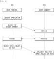
- FIG. 4 is a flowchart illustrating a method of changing a design of the smart garment 400 of a system according to the disclosed embodiment
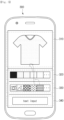
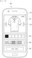
- FIG. 5 is a diagram illustrating a user interface for changing a design of the smart garment 400 according to the disclosed embodiment.
- An application for changing a design of the smart garment 400 may be installed in the user terminal 300.
- the application may provide a user interface related to pairing the smart garment 400 with the user terminal 300, changing a design of the smart garment 400, and the like through a display of the user terminal 300.
- the user terminal 300 searches for a nearby smart garment 400.
- the application may be executed by a command of a user, or may be automatically executed when the nearby smart garment 400 is sensed.
- An autorun function of the application may be changed through settings of the application.
- the user terminal 300 searches for the smart garment 400 and transmits a signal to the nearby smart garment 400 to be paired with the smart garment 400.
- the nearby smart garment 400 receives the signal transmitted from the user terminal 300 and transmits a signal in response to the received transmitted signal to the user terminal 300, the user terminal 300 and the smart garment 400 are paired.
- the pairing of the smart garment 400 and the user terminal 300 may be performed through a communication scheme, such as a LAN, Wi-Fi, Bluetooth, ZigBee, a UWB, IrDA, BLE, NFC, and the like.
- FIGS. 4 and 5 illustrate a case in which one smart garment 400 is found.
- a case in which a plurality of nearby smart garments 400 are found will be described below, and searching and pairing of the smart garment 400 will be described below in detail.
- the user interface shown in FIG. 5 is displayed on the display of the user terminal 300 once the user terminal 300 and the smart garment 400 are paired.
- the user interface may include a garment display area 310 at an upper portion thereof where an image of the paired smart garment 400 is displayed, a color selection area 320 displayed below the garment display area 310 and provided to allow a color of the smart garment 400 displayed in the garment display area 310 to be selected, an image selection area 330 displayed below the color selection area 320 and provided to allow an image to be implemented on the smart garment 400 displayed in the garment display area 310 to be selected, and a text input area 340 provided below the image selection area 330 and provided to allow text to be displayed on the smart garment 400 displayed in the garment display area 310 to be input.
- Positions of the garment display area 310, the color selection area 320, the image selection area 330, and the text input area 340 are not limited to the above-described positions, and may be variously set.
- the user may change the positions as desired through application settings.
- the user may select a desired color or image or may input text through the user interface, and the user terminal 300 transmits a signal including information selected or input through the user interface to the smart garment 400 so that the design of the smart garment 400 can be changed.
- the connection module 420 of the smart garment 400 may include at least the connector 428, as shown in FIG. 3 , or at least the communicator 427 and the driver 421 among the configuration shown in FIG. 2 .
- the image of the smart garment 400 displayed in the garment display area 310 may be a representative image set as a default in association with the paired smart garment 400.
- a representative image that does not reflect a shape or the like of the paired short-sleeved t-shirt and is designed to allow the user to intuitively recognize that the smart garment is a short-sleeved t-shirt may be displayed in the garment display area 310.
- an image similar to the actual smart garment 400 reflecting a current design of the smart garment 400 may be displayed in the garment display area 310, which will be described below with reference to FIG. 6 .
- the color selection area 320 may be displayed in various colors in a matrix form, as shown in FIG. 5 .
- the user may change the color of the smart garment 400 by touching a desired color among the colors displayed in the color selection area 320 or by selecting the color through a separate inputter, such as a keyboard or a mouse. Once the color is selected, the changed color may be reflected in the image of the smart garment 400 displayed in the garment display area 310.
- a manner in which colors are displayed in the color selection area 320 is not limited to the above-described example, and may be variously set.
- the user may change a display format of the colors through the application setting, and may set frequently used colors to be preferentially displayed.
- images such as photographs stored in the user terminal 300
- images may also be displayed in the image selection area 330.
- an object for driving a camera may also be displayed to display an image directly captured by the camera of the user terminal 300 on the smart garment 400. That is, when the user touches the object or clicks the object through an inputter, the camera installed in the user terminal 300 is driven so that the user can acquire a desired image by camera capturing.
- the captured image may be displayed on the smart garment 400 displayed in the garment display area 310. The user may select an image displayed in the image selection area 330 through application settings.
- only the images stored in advance in the user terminal 300 in association with the paired smart garment 400 may be set to be displayed, or only images such as photos stored in the user terminal 300 may be displayed.
- only the object for driving the camera may be set to be displayed so that the image directly captured by the camera of the user terminal 300 can be displayed on the smart garment 400.
- a representation such as ⁇ text input>, for allowing the user to know that a corresponding area is provided for text input may be displayed.
- the text input area 340 may be displayed as a blank space without a separate guide.
- the user terminal 300 displays a keyboard for text input to enable the user to input desired text.
- Text may be input through the keyboard or may be input via voice.
- the user may input text through the keyboard or input text via voice by application settings.
- An icon for guiding a keyboard input of text and an icon for guiding a voice input of text may be displayed in the text input area 340 so that the user can select a desired text input method by touching or clicking the icon for guiding the desired text input method.
- FIG. 6 is a flowchart illustrating a method of changing a design of a smart garment 400 of a system according to another disclosed embodiment
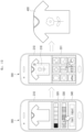
- FIGS. 7 and 8 are diagrams illustrating a user interface for searching for and pairing with the smart garment 400 displayed on a user terminal 300 according to the disclosed embodiment
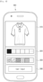
- FIG. 9 is a diagram illustrating a user interface for changing a design of the smart garment 400 according to another embodiment.
- the user terminal 300 searches for a nearby smart garment 400.
- the application may be executed by a command of a user, or may be automatically executed when the nearby smart garment 400 is sensed.
- An autorun function of the application may be changed through settings of the application.
- the user terminal 300 searches for the smart garment 400 and transmits a signal to the nearby smart garment 400 to be paired with the smart garment 400.
- the nearby smart garment 400 receives the signal transmitted from the user terminal 300 and transmits a signal in response to the received transmitted signal to the user terminal 300, the user terminal 300 and the smart garment 400 are paired.
- the user terminal 300 may provide the user interface for searching for the smart garment 400 and pairing with the found smart garment 400.
- the user interface may display a garment display area 311, a search button for searching for the nearby smart garment 400 below the garment display area 311, and a pairing button 314 for pairing with the found smart garment 400 in a display of the user terminal 300.
- Positions of the garment display area 311, the search button 312, and the pairing button 314 are not limited to the above-described positions, and may be variously set. For example, the user may change the positions as desired through application settings.
- an image of a magnifying glass may be displayed in the garment display area 311 so that the user can intuitively recognize that the nearby smart garment 400 is being searched for.
- images of the found smart garments 400 may be displayed in a matrix form in the garment display area 311, as shown in FIG. 8 .
- the user may select the smart garment 400 desired to be paired with among the smart garments 400 displayed in the garment display area 311 by touching or clicking the desired smart garment 400, and may pair the selected smart garment 400 with the user terminal 300 by touching or clicking the pairing button 314.
- the smart garment 400 extracts a current color thereof and a current image or text implemented on the smart garment 400 and transmits them to the user terminal 300.
- the connection module 420 of the smart garment 400 may include at least the communicator 427, the processor 423, the driver 421, and the memory 425, and design information of the current smart garment 400 may be stored in the memory 425.
- the user may select a desired color or image or input text through the user interface, and the user terminal 300 may transmit a signal including the information selected or input through the user interface to the smart garment 400 so that the design of the smart garment 400 can be changed.
- FIG. 10 is a flowchart illustrating a method of changing a design of a smart garment 400 of a system according to still another disclosed embodiment
- FIGS. 11 to 16 are diagrams illustrating a user interface for changing a design of the smart garment 400 according to still another disclosed embodiment.
- the user terminal 300 searches for a nearby smart garment 400.
- the application may be executed by a command of a user, or may be automatically executed when the nearby smart garment 400 is sensed.
- An autorun function of the application may be changed through settings of the application.
- the user terminal 300 searches for the smart garment 400 and transmits a signal to the nearby smart garment 400 to be paired with the smart garment 400.
- the nearby smart garment 400 receives the signal transmitted from the user terminal 300 and transmits a signal in response to the received transmitted signal to the user terminal 300, the user terminal 300 and the smart garment 400 are paired.
- a description of paring of the user terminal 300 and the smart garment 400 is the same as the description of FIGS. 6 to 8 , and thus will be omitted.
- connection module 420 of the smart garment 400 When the connection module 420 of the smart garment 400 is paired with the user terminal 300, the connection module 420 transmits identification information of the smart garment 400 to the user terminal 300 and the user terminal 300 transmits the identification information of the smart garment 400 transmitted from the smart garment 400 to the server 200.
- the connection module 420 of the smart garment 400 may include at least the communicator 427, the processor 423, the driver 421, and the memory 425, and design information or identification information of the current smart garment 400 may be stored in the memory 425.
- the user may select a desired color or image or input text through the user interface, and the user terminal 300 may transmit a signal including the information selected or input through the user interface to the smart garment 400 so that the design of the smart garment 400 can be changed.
- a method of changing a design of the paired smart garment 400 through the user interface provided by the user terminal 300 will be described in detail with reference to FIGS. 11 to 15 .
- a user interface of the user terminal 300 is similar to the user interface shown in FIG. 5 .
- the user interface shown in FIGS. 11 and 12 is different from the user interface shown in FIG. 5 in that an interface for changing the smart garment 400 displayed in the garment display area 310 to another found smart garment 400 and an interface 315 provided for a user to recognize that the smart garment 400 displayed in the garment display area 310 is a paired garment when the smart garment 400 is paired with the user terminal 300 are further displayed in the garment display area 310.
- the user may touch or click the interface for changing the smart garment 400.
- the user may input a drag gesture or a flick gesture among touch gestures to the garment display area 310 to change the smart garment 400 displayed in the garment display area 310 to another smart garment 400.
- the color selection area 320, the image selection area 330, and the text input area 340 are changed to suit the changed smart garment 400.
- a representation that conveys a meaning that text input is not possible for example, ⁇ none>, is displayed in the text input area 349, as shown in FIG. 12 .
- the user terminal 300 when the changed smart garment 400 is a smart garment that is not paired with the user terminal 300, the user terminal 300 does not display the interface indicating the pairing.
- the user terminal 300 displays an interface indicating that the displayed smart garment 400 is paired with the user terminal 300.
- the user may change the image of the smart garment 400 by touching or clicking the image, pattern, or design displayed in the image selection area 330.
- an object for selecting photographs stored in the user terminal 300 may be displayed in the image selection area 330 in addition to the images transmitted from the server 200.
- the images stored in the user terminal 300 may be displayed in a matrix form below the garment display area.
- an area 316 in which an image can be displayed is displayed in a rectangular shape on the smart garment 400 displayed in the garment display area 310 so that the user can recognize where the image selected by the user is displayed on the smart garment 400.
- the user may change a shape, size, or position of the area displayed on the smart garment 400 in the garment display area 310.
- the user terminal 300 transmits a signal including information for implementing the selected image on the smart garment 400 to the smart garment 400 so that the selected image is displayed on the smart garment 400.
- the user terminal 300 may directly forward the signal for implementing the image to the smart garment 400, or may display a message requesting confirmation of the application of the selected image and forward the signal for implementing the image to the smart garment 400 when a confirmation command is input.
- an object for driving the camera may also be displayed in the image selection area 330 so that an image directly captured by the camera of the user terminal 300 can be displayed on the smart garment 400.
- the user terminal 300 may directly forward a signal for implementing the captured image on the smart garment 400, or may display a message requesting confirmation of application of the captured image and then forward the signal for implementing the image to the smart garment 400 when a confirmation command is received.
- a representation such as ⁇ text input>, may be displayed that allows the user to know that a corresponding area is provided for text input.
- the text input area 340 may be displayed as a blank space without a separate guide.
- the user terminal 300 displays an area provided for selecting a color of text and a keyboard for inputting text, as shown in FIG. 15 , so that the user can input text of a desired color.
- an area 341 in which text can be displayed is displayed in a rectangular shape on the smart garment 400 displayed in the garment display area 310 so that the user can recognize where the image selected by the user is displayed on the smart garment 400.
- the user may change a shape, size, or position of the text display area displayed on the smart garment 400 in the garment display area 310.
- a user interface for selecting a text font may be further displayed to allow the user to select a desired font.
- the input text is displayed on the smart garment 400 displayed in the garment display area 310.
- the user terminal 300 transmits a signal including information for implementing the input text on the smart garment 400 to the smart garment 400 so that the input text can be displayed on the smart garment 400.
- the user terminal 300 may directly forward a signal for displaying the text to the smart garment 400, or may display a message requesting confirmation of application of the input text and then forward the signal for displaying the text to the smart garment 400 when a confirmation command is input.
- the text may be input through a keyboard or input via voice.
- the user may input text through the keyboard or via voice by application settings.
- An icon for guiding keyboard input of text and an icon for guiding voice input of text may be displayed in the text input area 340 so that the user can select a desired text input method by touching or clicking the icon for guiding the desired text input method.
- the user interface shown in FIG. 15 may be displayed.
- the input text may be displayed on the smart garment 400 displayed in the garment display area 310.
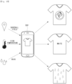
- the design of the smart garment 400 may be changed through the user interface provided by the user terminal 300, or the user terminal 300 may sense information of the surrounding environment and automatically change the design of the smart garment 400, which will be described with reference to FIG. 16 .
- the user terminal 300 may recognize a position of the user terminal 300 or detect a surrounding temperature or weather using a sensor mounted on the user terminal 300 or by utilizing Internet information or the like.
- the position, temperature, and weather are examples of environment information that the user terminal 300 can detect, but the present invention is not limited thereto.
- the user terminal 300 may transmit a signal to the smart garment 400 such that a symbol of a team playing a game at the baseball field can be implemented on the smart garment 400.
- the smart garment 400 may display the symbol of the team according to the signal transmitted from the user terminal 300.
- the user terminal 300 may transmit a signal for changing a color of the current smart garment 400 to white to the smart garment 400.
- the smart garment 400 may change the color thereof to white according to the signal transmitted from the user terminal 300.
- the smart garment 400 may not change the color.
- the user terminal 300 may transmit a signal for changing a pattern, a design, or an image currently displayed on the smart garment 400 to a raindrop image, design, or pattern to the smart garment 400.
- the smart garment 400 may change the current pattern, design, or image thereof to the raindrop pattern, design, or image according to the signal transmitted from the user terminal 300.
- An application may provide a surrounding environment recognition mode that provides the above-described functions, and the user may activate the surrounding environment recognition mode to automatically cause the user terminal 300 to change the design of the smart garment 400.
- the surrounding environment recognition mode may be usually turned off and optionally activated in a desired situation.
- the smart garment 400 includes a fabric including color-changing fibers and ordinary fibers, which are materials for changing an image, text, or color according to a signal transmitted from the user terminal 300, and the above-described connection module 420.
- color-changing fibers and ordinary fibers which are materials for changing an image, text, or color according to a signal transmitted from the user terminal 300
- connection module 420 the color-changing fibers constituting the smart garment 400
- FIGS. 17 to 20 are diagrams illustrating cholesteric liquid crystal fibers among the color-changing fibers of the smart garment 400 according to the disclosed embodiment.
- cholesteric liquid crystal fiber 419 may have a circular or polygonal cross-section.
- the cholesteric liquid crystal fiber has a cholesteric liquid crystal 415 provided at the center of the fiber, a first electrode 412a formed on a part of an outer surface of the cholesteric liquid crystal, a second electrode 412b formed at an opposite surface of the first electrode, an insulator 413 provided between the first electrode and the second electrode, and a protective layer 411 covering the first electrode, the second electrode, and the insulator.
- Cholesteric liquid crystals have bistability such that the cholesteric liquid crystals may be present in two stable states, such as a planar state in which light is reflected even when no voltage is applied to the cholesteric liquid crystals and a focal conic state in which light is scattered.
- the cholesteric liquid crystals may be converted into a homeotropic state in which light can be transmitted when a high voltage is applied thereto.
- the changed design may be maintained without the application of voltage.
- An inner electrode and an outer electrode may be transparent electrodes made of a transparent conductive material, and examples of the transparent conductive material may include indium tin oxide (ITO), indium zinc oxide (IZO), aluminum-doped zinc oxide (ZAO), a silver nano-wire (AgNW), and the like.
- ITO indium tin oxide
- IZO indium zinc oxide
- ZAO aluminum-doped zinc oxide
- AgNW silver nano-wire
- the protective layer covering the first electrode, the second electrode, and the insulator may be formed by coating ordinary textile fibers or fibers in a mesh form.
- ordinary textile fibers as the protective layer, a texture of ordinary textile fibers may be imparted to the cholesteric liquid crystal fiber.
- the first electrode and the second electrode may be connected to the driver 421 of the connection module 420, and the driver 421 may change the design of the smart garment 400 by applying a voltage to the first electrode and the second electrode according to a control signal of the processor 423.
- the cholesteric liquid crystal fiber may include a partition wall 416 for maintaining a shape of the fiber in the cholesteric liquid crystals.
- the partition wall may be formed by a polymer structure.
- the cholesteric liquid crystal fiber may be provided to have a polygonal cross-section, such as a quadrangular cross-section.
- the above-described cholesteric liquid crystal fiber may be combined with an ordinary textile fiber 490 to form a color-changing fiber constituting the smart garment 400.
- the cholesteric liquid crystal fiber and the ordinary textile fiber may be formed to have a twisted structure.
- a fabric of the smart garment 400 according to the disclosed embodiment may be formed by weaving color-changing fibers having a twisted form of cholesteric liquid crystal fibers and textile fibers.
- the above-described first electrode and second electrode may not be formed on the cholesteric liquid crystal fiber, but the first electrode and the second electrode may be formed on one surface of the woven fabric and an opposite surface thereof.
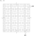
- the fabric of the smart garment 400 may be formed by weaving the cholesteric liquid crystal fibers 430 and the ordinary textile fibers 422 in the form of a net.
- the fabric is formed by weaving the cholesteric liquid crystal fibers and the textile fibers in the form of a net without weaving the fabric using color-changing fibers having a twisted structure of cholesteric liquid crystal fibers and textile fibers.
- FIG. 20 illustrates a structure of pixels P of a cholesteric liquid crystal fiber according to the disclosed embodiment.
- the cholesteric liquid crystal fiber may have a structure in which red pixels reflecting one color of light, for example, red light, are arranged in a single layer.
- red pixels reflecting one color of light for example, red light
- cholesteric liquid crystal fibers arranged in adjacent columns or in adjacent rows in the form shown in FIG. 19 may be provided to reflect different colors.
- one pixel P constituting the cholesteric liquid crystal fiber may have a structure in which a red sub-cell 431 reflecting a wavelength band corresponding to red light, a green sub-cell 432 reflecting a wavelength band corresponding to green light, and a blue sub-cell 433 reflecting a wavelength band corresponding to blue light are stacked atop one another.
- one pixel may have a stacked structure, or, as shown in FIGS. 20C and 20D , one pixel may have a structure in which a red sub-cell reflecting a wavelength band corresponding to red light, a green sub-cell reflecting a wavelength band corresponding to green light, and a blue sub-cell reflecting a wavelength band corresponding to blue light are arranged in a single layer.
- a grid 434 that separates each of sub-cells constituting one pixel may be implemented by an ordinary textile fiber material so that cholesteric liquid crystal fibers may have a texture of textile fibers.
- the grid may be formed to have a height higher than the cholesteric liquid crystals, as shown in FIG. 20C , or may be formed at the same height as the cholesteric liquid crystals, as shown in FIG. 20D .
- a grid separating each sub-cell may be implemented by an ordinary textile fiber material so that cholesteric liquid crystal fibers may have a texture of textile fibers.
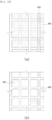
- FIGS. 21 and 22 illustrate a connection structure of the color-changing fiber and the fabric of the smart garment 400 according to the disclosed embodiment.
- the cholesteric liquid crystal fiber since the cholesteric liquid crystal fiber includes the first electrode and the second electrode to which a voltage is applied, as described above, when cholesteric liquid crystal fibers 419 are connected to each other, electrodes of the same polarity should be electrically connected. That is, first electrodes of the cholesteric liquid crystal fibers to be connected should be electrically connected to each other, and second electrodes should be electrically connected to each other. As shown in FIG.
- a cross-section of the connection portion may be formed to be circular when a cross-section of the cholesteric liquid crystal fiber is circular, and the cross-section of the connection portion may be formed to be polygonal corresponding to the cross-section of the cholesteric liquid crystal fiber when the cross-section of the cholesteric liquid crystal fiber is polygonal.
- first electrode and the second electrode are formed in the woven fabric, as described above.
- first electrodes of fabrics 450 to be connected should be electrically connected to each other, and second electrodes should be electrically connected to each other.
- a connection portion 455 of the fabric may include a first connection electrode 455a which connects the first electrodes 450a formed on top surfaces of the fabrics to be connected and a second connection electrode 455b which connects the second electrodes 450b formed on bottom surfaces of the fabrics to be connected.
- FIG. 22A illustrates a cross-section of the fabrics to be connected and the connection portion which connects the fabrics
- FIG. 22B illustrates the top surface.
- outer electrodes illustrated by solid lines are the first connection electrodes and outer electrodes illustrated by dotted lines are the second connection electrodes.
- the fabric of the smart garment 400 may be formed using the color-changing fibers having the twisted structure shown in FIG. 18 , or may be formed by weaving cholesteric liquid crystal fibers and ordinary textile fibers in the form of a net as shown in FIG. 19 .
- a flexible cholesteric liquid crystal in the form of a film may be used.
- FIG. 23 is a diagram illustrating a structure of the fabric of the smart garment 400 according to the disclosed embodiment.
- the flexible cholesteric liquid crystal 460 may be formed into a net shape by forming holes in the form of a matrix in the flexible cholesteric liquid crystal and inserting an ordinary textile fiber 455 into a net eye, i.e., the hole, such that the fabric of the smart garment 400 is formed.
- textile fibers may be formed into a net shape by forming holes in the form of a matrix in the ordinary textile fibers and combining the flexible cholesteric liquid crystal 460 into a net eye, i.e., the hole, such that the fabric of the smart garment 400 is formed.
- the cholesteric liquid crystal illustrated in FIGS. 23A and 23B may include pixels of a stacked structure or pixels of a single layer structure, as described above.
- the cholesteric liquid crystals of FIG. 23A may be individually controlled for each line, and the cholesteric liquid crystals of FIG. 23B may also be individually controlled for each cholesteric liquid crystal forming the net eye.
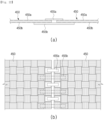
- FIG. 24 is a diagram illustrating a connection relationship of color-changing fibers and the connection module 420 for control of the color-changing fibers of the smart garment 400 according to the disclosed embodiment.
- one of a first electrode 430a-1 and a second electrode 430a-2 of a cholesteric liquid crystal fiber 430a as a first material and a second material that constitute a fabric may perform a role of a signal electrode, and the other may perform a role of a ground electrode.
- one of a third electrode 430b-1 and a fourth electrode 430b-2 may perform a role of a signal electrode, and the other may perform a role of a ground electrode.
- the cholesteric liquid crystal fiber has been described above as an example of the color-changing fiber for changing a design of the smart garment 400.
- other embodiments of the color-changing fiber will be described.
- FIG. 25 is a diagram illustrating electronic ink fibers among the color-changing fibers of the smart garment 400 according to the disclosed embodiment.
- the electronic ink capsules may contain at least one of a red electronic ink reflecting red light, a green electronic ink reflecting green light, a blue electronic ink reflecting blue light, a black electronic ink that absorbs light, and a white electronic ink that reflects light.
- the red electronic ink, the black electronic ink, and the white electronic ink may be contained in one capsule
- the green electronic ink, the black electronic ink, and the white electronic ink may be contained in one capsule
- the blue electronic ink, the black electronic ink, and the white electronic ink may be contained in one capsule.
- An inner electrode and an outer electrode may be transparent electrodes made of a transparent conductive material, and examples of the transparent conductive material may include ITO, IZO, aluminum-doped ZAO, AgNW, and the like.
- the protective layer covering the first electrode, the second electrode, and the insulator may be formed by coating ordinary textile fibers or fibers in a mesh form.
- the fabric of the smart garment 400 according to the present embodiment may be formed by color-changing fibers having a twisted structure of the electronic ink fibers and the ordinary textile fibers, as in the embodiment using the cholesteric liquid crystal fibers, or may be formed by weaving the electronic ink fibers and the ordinary textile fibers in the form of a net.
- the above-described first electrode and second electrode may not be formed on the electronic ink fiber, but the first electrode and the second electrode may be formed on one surface of the woven fabric and an opposite surface.
- the electronic ink also has bistability like the above-described cholesteric liquid crystal, power required for changing a design of the smart garment 400 may be minimized.
- FIG. 26 is a diagram illustrating an electrochromic fiber among color-changing fibers of the smart garment 400 according to the disclosed embodiment.
- the electrochromic fiber 480 may include a first electrode 482, a counter electrode 489 provided outside the first electrode, an electrolyte 487 provided outside the counter electrode, a working electrode 485 provided outside the electrolyte, a second electrode 483 provided outside the working electrode, and a protective layer 481 provided to cover the second electrode.
- a partition wall for maintaining a shape of the fiber may be provided inside the electrochromic fiber.
- the first electrode will be referred to as an inner electrode since it is provided inside the fiber, and the second electrode will be referred to as an outer electrode.
- At least one of the working electrode and the counter electrode includes a color-changing material.
- the working electrode may include a material that changes color as it is reduced
- the counter electrode may include a material that changes color as it is oxidized.
- Both the working electrode and the counter electrode may include the above-described color-changing material, or only one of the working and counter electrodes may include the above-described color-changing material while the other may include an ion-receiving electrode.
- Typical reducing color-changing materials include W03 and MoO3 TiO2, and oxidative color-changing materials include Ir(OH)x, Ni(OH)2, and Rh2O3.
- the electrochromic fiber may realize different red colors, green colors, and blue colors and combinations thereof in the color-changing material, and may be changed to a transparent state.
- the protective layer may be formed by coating ordinary textile fibers or fibers in a mesh form. By using ordinary textile fibers as the protective layer, a texture of the ordinary textile fiber may be imparted to the electrochromic fiber.
- the inner electrode and the outer electrode may be connected to the driver 421 of the connection module 420, and the driver 421 may change the design of the smart garment 400 by applying a voltage to the first electrode and the second electrode according to a control signal of the processor 423.
- a fabric of the smart garment 400 according to the present embodiment may be formed by mixing electrochromic fibers and ordinary textile fibers, as in the embodiment using the cholesteric liquid crystal fabric. Since the electrochromic material also has bistability like the above-described cholesteric liquid crystal, power required for changing a design of the smart garment 400 may be minimized.
- FIG. 27 is a diagram illustrating electroluminescent fibers among color-changing fibers of the smart garment 400 according to the disclosed embodiment.
- connection module 420 of the smart garment 400 includes the battery 429.
- the first electrode will be referred to as an inner electrode since it is provided inside the fiber, and the second electrode will be referred to as an outer electrode.
- a material that emits white light is used as the luminescent material, and color filters 492a, 492b, and 492c, which transmit red light, green light, and blue light, respectively, may be attached to outer surfaces of the outer electrodes to form the electroluminescent fiber.
- the outer electrodes are spaced apart from each other, and the aforementioned color filters are attached respectively to the outer electrodes provided at a distance from each other.
- each of the outer electrodes may be individually controlled by the driver 421 of the connection module 420.
- a partition wall for maintaining a shape of the fiber may be provided inside the luminescent material.
- materials 495a, 495b, and 495c that emit red light, green light, and blue light, respectively, are used as the luminescent material, and an outer electrode is provided outside each of the materials to form the electroluminescent fiber.
- the outer electrodes may be spaced apart from each other, and may be individually controlled by the driver 421 of the connection module 420.
- a core of the electroluminescent fiber is formed by an organic textile fiber 494, and three inner electrodes spaced apart from each other are formed outside the textile fiber.
- materials 495a, 495b, and 495c which emit red light, green light, and blue light, respectively, may be provided as luminescent materials formed outside of the inner electrodes, and outer electrodes may be provided respectively outside of the materials to form the electroluminescent fiber.
- inner and outer electrodes that apply voltages to different luminescent materials may be individually controlled by the driver 421 of the connection module 420.
- the inner electrode and the outer electrode are transparent electrodes made of a transparent conductive material.
- the transparent conductive material may include ITO, IZO, aluminum-doped ZAO, AgNW, and the like.
- the inner electrode and the outer electrode may be formed in a planar shape or in a linear shape.
- a protective layer may be formed by coating ordinary textile fibers or fibers in a mesh form. By using ordinary textile fibers as the protective layer, a texture of the ordinary textile fibers may be imparted to the electroluminescent fiber.
- the inner electrode and the outer electrode may be connected to the driver 421 of the connection module 420, and the driver 421 may change the design of the smart garment 400 by applying a voltage to the inner electrode and the outer electrode according to the control signal of the processor 423.
- the fabric of the smart garment 400 according to the present embodiment may be formed by mixing the electrochromic fibers and the ordinary textile fibers, as in the embodiment using the cholesteric liquid crystal fibers.
Landscapes
- Engineering & Computer Science (AREA)
- Physics & Mathematics (AREA)
- General Physics & Mathematics (AREA)
- Nonlinear Science (AREA)
- Textile Engineering (AREA)
- Theoretical Computer Science (AREA)
- Business, Economics & Management (AREA)
- Optics & Photonics (AREA)
- Chemical & Material Sciences (AREA)
- Finance (AREA)
- Accounting & Taxation (AREA)
- Strategic Management (AREA)
- Crystallography & Structural Chemistry (AREA)
- Signal Processing (AREA)
- General Business, Economics & Management (AREA)
- Economics (AREA)
- Marketing (AREA)
- General Engineering & Computer Science (AREA)
- Health & Medical Sciences (AREA)
- Computer Hardware Design (AREA)
- Development Economics (AREA)
- Mathematical Physics (AREA)
- General Health & Medical Sciences (AREA)
- Multimedia (AREA)
- Human Computer Interaction (AREA)
- Manufacturing & Machinery (AREA)
- Human Resources & Organizations (AREA)
- Primary Health Care (AREA)
- Tourism & Hospitality (AREA)
- Computer Networks & Wireless Communication (AREA)
- Medical Informatics (AREA)
- Computing Systems (AREA)
- Chemical Kinetics & Catalysis (AREA)
- Dispersion Chemistry (AREA)
- Molecular Biology (AREA)
- Electrochemistry (AREA)
- Geometry (AREA)
- Life Sciences & Earth Sciences (AREA)
- Mechanical Engineering (AREA)
- Entrepreneurship & Innovation (AREA)
Applications Claiming Priority (4)
| Application Number | Priority Date | Filing Date | Title |
|---|---|---|---|
| KR1020150139231A KR102550736B1 (ko) | 2015-10-02 | 2015-10-02 | 스마트 의류, 사용자 단말, 이를 포함하는 시스템 및 스마트 의류의 디자인 변경방법 |
| PCT/KR2016/003403 WO2017057811A1 (ko) | 2015-10-02 | 2016-04-01 | 스마트 의류, 사용자 단말, 이를 포함하는 시스템 및 스마트 의류의 디자인 변경방법 |
| EP16851959.3A EP3340160A4 (de) | 2015-10-02 | 2016-04-01 | Intelligentes kleidungsstück, benutzerendgerät, system damit und verfahren zum ändern des designs eines intelligenten kleidungsstücks |
| EP21175526.9A EP3944008B1 (de) | 2015-10-02 | 2016-04-01 | Intelligentes kleidungsstück |
Related Parent Applications (2)
| Application Number | Title | Priority Date | Filing Date |
|---|---|---|---|
| EP21175526.9A Division EP3944008B1 (de) | 2015-10-02 | 2016-04-01 | Intelligentes kleidungsstück |
| EP16851959.3A Division EP3340160A4 (de) | 2015-10-02 | 2016-04-01 | Intelligentes kleidungsstück, benutzerendgerät, system damit und verfahren zum ändern des designs eines intelligenten kleidungsstücks |
Publications (2)
| Publication Number | Publication Date |
|---|---|
| EP4474894A2 true EP4474894A2 (de) | 2024-12-11 |
| EP4474894A3 EP4474894A3 (de) | 2025-01-22 |
Family
ID=58427753
Family Applications (3)
| Application Number | Title | Priority Date | Filing Date |
|---|---|---|---|
| EP24209291.4A Pending EP4474894A3 (de) | 2015-10-02 | 2016-04-01 | Intelligentes kleidungsstück |
| EP21175526.9A Active EP3944008B1 (de) | 2015-10-02 | 2016-04-01 | Intelligentes kleidungsstück |
| EP16851959.3A Ceased EP3340160A4 (de) | 2015-10-02 | 2016-04-01 | Intelligentes kleidungsstück, benutzerendgerät, system damit und verfahren zum ändern des designs eines intelligenten kleidungsstücks |
Family Applications After (2)
| Application Number | Title | Priority Date | Filing Date |
|---|---|---|---|
| EP21175526.9A Active EP3944008B1 (de) | 2015-10-02 | 2016-04-01 | Intelligentes kleidungsstück |
| EP16851959.3A Ceased EP3340160A4 (de) | 2015-10-02 | 2016-04-01 | Intelligentes kleidungsstück, benutzerendgerät, system damit und verfahren zum ändern des designs eines intelligenten kleidungsstücks |
Country Status (8)
| Country | Link |
|---|---|
| US (2) | US11140926B2 (de) |
| EP (3) | EP4474894A3 (de) |
| JP (1) | JP6966430B2 (de) |
| KR (1) | KR102550736B1 (de) |
| CN (2) | CN108140215A (de) |
| AU (2) | AU2016329815A1 (de) |
| CA (1) | CA2998701A1 (de) |
| WO (1) | WO2017057811A1 (de) |
Families Citing this family (26)
| Publication number | Priority date | Publication date | Assignee | Title |
|---|---|---|---|---|
| CN106249979B (zh) * | 2016-08-31 | 2019-05-31 | 京东方科技集团股份有限公司 | 触控电极结构以及触控显示装置 |
| KR20200015510A (ko) * | 2017-05-03 | 2020-02-12 | 더 노스 훼이스 어패럴 코오포레이션 | 웨어러블 매체를 제어하기 위한 시스템 |
| US11180871B2 (en) | 2017-06-14 | 2021-11-23 | Apple Inc. | Fabric items having strands of adjustable appearance |
| US10962816B2 (en) | 2017-06-16 | 2021-03-30 | E Ink Corporation | Flexible color-changing fibers and fabrics |
| CN111527243A (zh) | 2017-10-18 | 2020-08-11 | 佛罗里达中心大学研究基金会有限公司 | 具有导电芯和变色涂层的纤维 |
| TW201937403A (zh) * | 2018-02-21 | 2019-09-16 | 美商促美股份有限公司 | 具有可配置視覺外觀之服裝及自動配置該服裝之系統、方法及物品 |
| US11868018B2 (en) * | 2018-04-10 | 2024-01-09 | The Hong Kong Research Institute Of Textiles And Apparel Limited | Electrochromic elements, devices and products, and methods for manufacturing and utilizing the same |
| US11635640B2 (en) | 2018-10-01 | 2023-04-25 | E Ink Corporation | Switching fibers for textiles |
| CN112740087B (zh) | 2018-10-01 | 2023-07-04 | 伊英克公司 | 电光纤维及其制造方法 |
| US12181768B2 (en) | 2018-10-01 | 2024-12-31 | E Ink Corporation | Light-transmissive conductor with directional conductivity |
| KR102152293B1 (ko) * | 2018-10-31 | 2020-09-04 | 김광형 | 광섬유를 이용한 자동차의 색상 가변시스템 |
| KR102028589B1 (ko) * | 2019-03-04 | 2019-10-18 | 김갑두 | 스마트 의류 |
| KR102035743B1 (ko) | 2019-06-18 | 2019-11-26 | (주)킨사이트 | 의류 또는 잡화 부착 디스플레이 시스템 및 방법 |
| CN110346958A (zh) * | 2019-06-28 | 2019-10-18 | 电子科技大学 | 基于多稳态胆甾型液晶的电致变色纤维器件及制备方法 |
| US11761123B2 (en) | 2019-08-07 | 2023-09-19 | E Ink Corporation | Switching ribbons for textiles |
| KR102872425B1 (ko) * | 2019-12-05 | 2025-10-17 | 엘지전자 주식회사 | Xr 디바이스 및 그 제어 방법 |
| US11641890B2 (en) | 2020-01-31 | 2023-05-09 | Kyndryl, Inc. | Wearer physical status indication using an electronically adjustable garment |
| US11479886B2 (en) | 2020-05-21 | 2022-10-25 | University Of Central Florida Research Foundation, Inc. | Color-changing fabric and applications |
| US11708649B2 (en) | 2020-05-21 | 2023-07-25 | University Of Central Florida Research Foundation, Inc. | Color-changing fabric having printed pattern |
| CN112486117B (zh) * | 2020-11-26 | 2021-12-24 | 深圳乐豆互联网工业科技有限公司 | 基于自动化识别数据输入的服装加工方法 |
| JP2022096040A (ja) * | 2020-12-17 | 2022-06-29 | トヨタ自動車株式会社 | マッチング情報提供方法およびマッチング情報提供プログラム |
| MX2023007794A (es) * | 2021-01-04 | 2023-07-10 | Driverdo Llc | Dispositivo electronico portatil para mostrar informacion. |
| CN113745426B (zh) * | 2021-08-31 | 2023-11-28 | 深圳市华星光电半导体显示技术有限公司 | 发光纤维及其制备方法 |
| USD1006823S1 (en) * | 2021-10-01 | 2023-12-05 | Xerox Corporation | Display screen or portion thereof with print icon |
| WO2024206983A1 (en) * | 2023-03-31 | 2024-10-03 | Regents Of The University Of Minnesota | Textile architectures for repositionable components |
| KR102638912B1 (ko) | 2023-08-22 | 2024-02-21 | 주식회사 앱포스터 | Nfc 태깅을 이용한 워치페이스 제공 방법 및 장치 |
Family Cites Families (32)
| Publication number | Priority date | Publication date | Assignee | Title |
|---|---|---|---|---|
| US5150234A (en) * | 1988-08-08 | 1992-09-22 | Olympus Optical Co., Ltd. | Imaging apparatus having electrooptic devices comprising a variable focal length lens |
| JP2003041420A (ja) | 2001-07-25 | 2003-02-13 | Gonshichi Shoten:Kk | 衣類の販売方法および試着印刷システム |
| JP2003113508A (ja) * | 2001-10-02 | 2003-04-18 | Matsushita Electric Ind Co Ltd | コンテンツ再生機能付き装着品及びコンテンツ再生機能付き衣服並びにコンテンツ再生機能付き装着品又は衣服を用いた広告方法 |
| US20030090598A1 (en) * | 2001-11-13 | 2003-05-15 | Johngren Jeanne Muller | Method and apparatus for displaying digital images on an article worn by a user |
| JP2003280049A (ja) * | 2002-03-26 | 2003-10-02 | Tdk Corp | 機能性ファイバーおよび機能性ファイバーを用いた織編物 |
| US20050289018A1 (en) * | 2004-06-07 | 2005-12-29 | Todd Sullivan | Online personalized apparel design and sales technology with associated manufacturing and fulfillment techniques and processes |
| US8015245B2 (en) * | 2006-04-24 | 2011-09-06 | Microsoft Corporation | Personalized information communications |
| JP2009543277A (ja) * | 2006-06-29 | 2009-12-03 | コーニンクレッカ フィリップス エレクトロニクス エヌ ヴィ | ピクセル化エレクトロルミネセント・テキスタイル |
| JP4868974B2 (ja) | 2006-08-10 | 2012-02-01 | 富士通株式会社 | デザイン配信方法およびデザイン配信装置 |
| KR100900507B1 (ko) | 2006-10-09 | 2009-06-03 | 가부시키가이샤 테크노아 | 구매자 또는 판매자가 디자인한 의복을 인터넷을 통해판매하는 시스템 및 이를 이용한 의복 판매 방법 |
| US7698101B2 (en) * | 2007-03-07 | 2010-04-13 | Apple Inc. | Smart garment |
| KR101387522B1 (ko) | 2007-11-05 | 2014-04-23 | 엘지전자 주식회사 | 냉장고 및 그 제어방법 |
| KR101435813B1 (ko) | 2007-11-27 | 2014-08-29 | 엘지전자 주식회사 | 세탁물 처리장치 및 그 제어방법 |
| KR20090055133A (ko) | 2007-11-28 | 2009-06-02 | 엘지전자 주식회사 | 냉장고 및 냉장고의 냉기 공급장치 |
| US20090310290A1 (en) * | 2008-06-11 | 2009-12-17 | Tennent James | Wearable display media |
| KR20100041406A (ko) | 2008-10-14 | 2010-04-22 | 김상식 | 이벤트 광고 홍보용 스마트 의류 및 이를 이용한 작동 구현방법 |
| KR101478030B1 (ko) | 2009-01-29 | 2014-12-31 | 삼성전자주식회사 | 블루투스 기기 검색 및 연결 방법과 이를 이용한 장치 |
| EP2414892B1 (de) * | 2009-03-31 | 2014-06-11 | University of Connecticut | Flexible elektrochrome anordnung, elektroden dafür und herstellungsverfahren |
| EP2449517A4 (de) * | 2009-06-30 | 2014-08-27 | Nike Innovate Cv | Design für verbraucherprodukte |
| KR20110028056A (ko) * | 2009-09-11 | 2011-03-17 | 삼성전자주식회사 | 블루투스 통신 연결 방법 및 시스템 |
| US8257639B2 (en) * | 2009-09-22 | 2012-09-04 | Kent State University | Method of making stimuli responsive liquid crystal-polymer composite fibers |
| JP2012039282A (ja) | 2010-08-05 | 2012-02-23 | Fujitsu Ltd | 電子機器、その情報表示プログラム及びその情報表示方法 |
| KR101142192B1 (ko) * | 2010-11-05 | 2012-05-14 | 주식회사 엘티전자 | 광섬유 직물 디스플레이를 구비한 스마트 의류 제어시스템 및 그의 스마트 폰을 연동한 제어방법 |
| US20120184367A1 (en) | 2011-01-14 | 2012-07-19 | Igt | Wearable casino gaming display and tracking system |
| JP2015511003A (ja) * | 2012-03-05 | 2015-04-13 | コモンウェルス サイエンティフィック アンド インダストリアル リサーチ オーガニゼーション | 複合センサファイバおよびその用途 |
| KR20130136205A (ko) | 2012-06-04 | 2013-12-12 | 위니아만도 주식회사 | 냉장고 |
| KR102039553B1 (ko) * | 2012-08-31 | 2019-11-01 | 삼성전자 주식회사 | 사용자 디바이스에서 입력 문자를 이용한 지능형 서비스 제공 방법 및 장치 |
| WO2014047185A2 (en) | 2012-09-18 | 2014-03-27 | Miller Resort Llc | Modifiable display devices and systems |
| US10089680B2 (en) * | 2013-03-12 | 2018-10-02 | Exalibur Ip, Llc | Automatically fitting a wearable object |
| KR102300190B1 (ko) | 2014-03-11 | 2021-09-08 | 주식회사 엘지유플러스 | 의류 조회 서비스 제공 시스템 및 방법 |
| US9959080B2 (en) * | 2014-05-01 | 2018-05-01 | Rageon, Inc. | Transfer of mobile device camera image to an image-supporting surface |
| US11024219B2 (en) * | 2015-08-20 | 2021-06-01 | Drexel University | Direct integration of individually controlled pixels into a knitted fabric matrix |
-
2015
- 2015-10-02 KR KR1020150139231A patent/KR102550736B1/ko active Active
-
2016
- 2016-04-01 EP EP24209291.4A patent/EP4474894A3/de active Pending
- 2016-04-01 AU AU2016329815A patent/AU2016329815A1/en not_active Abandoned
- 2016-04-01 EP EP21175526.9A patent/EP3944008B1/de active Active
- 2016-04-01 WO PCT/KR2016/003403 patent/WO2017057811A1/ko not_active Ceased
- 2016-04-01 EP EP16851959.3A patent/EP3340160A4/de not_active Ceased
- 2016-04-01 US US15/765,484 patent/US11140926B2/en active Active
- 2016-04-01 JP JP2018516435A patent/JP6966430B2/ja active Active
- 2016-04-01 CN CN201680057459.2A patent/CN108140215A/zh active Pending
- 2016-04-01 CA CA2998701A patent/CA2998701A1/en active Pending
- 2016-04-01 CN CN202211005881.7A patent/CN115399525B/zh active Active
-
2021
- 2021-10-11 US US17/498,498 patent/US12035761B2/en active Active
-
2022
- 2022-03-03 AU AU2022201463A patent/AU2022201463B2/en active Active
Also Published As
| Publication number | Publication date |
|---|---|
| US11140926B2 (en) | 2021-10-12 |
| JP2019504372A (ja) | 2019-02-14 |
| CN115399525B (zh) | 2025-11-14 |
| AU2022201463A1 (en) | 2022-03-24 |
| KR20170039967A (ko) | 2017-04-12 |
| EP4474894A3 (de) | 2025-01-22 |
| CN108140215A (zh) | 2018-06-08 |
| KR102550736B1 (ko) | 2023-07-04 |
| US20180271180A1 (en) | 2018-09-27 |
| WO2017057811A1 (ko) | 2017-04-06 |
| EP3944008B1 (de) | 2024-11-20 |
| US12035761B2 (en) | 2024-07-16 |
| US20220026769A1 (en) | 2022-01-27 |
| EP3944008A1 (de) | 2022-01-26 |
| CA2998701A1 (en) | 2017-04-06 |
| CN115399525A (zh) | 2022-11-29 |
| EP3944008C0 (de) | 2024-11-20 |
| EP3340160A1 (de) | 2018-06-27 |
| AU2016329815A1 (en) | 2018-04-12 |
| EP3340160A4 (de) | 2018-06-27 |
| JP6966430B2 (ja) | 2021-11-17 |
| AU2022201463B2 (en) | 2023-11-23 |
Similar Documents
| Publication | Publication Date | Title |
|---|---|---|
| AU2022201463B2 (en) | Smart garment, user terminal, system including same, and method of changing design of smart garment | |
| KR102394718B1 (ko) | 전자 장치 및 어플리케이션 실행 방법 | |
| KR102360492B1 (ko) | 플렉시블 디스플레이 및 이를 포함하는 전자 장치 | |
| JP6545569B2 (ja) | 移動端末機及びその制御方法 | |
| US10613655B2 (en) | Rollable mobile terminal and control method therefor | |
| TWI708221B (zh) | 顯示面板及資料處理裝置 | |
| US20110007037A1 (en) | Electronic pen and electronic pen system | |
| KR102266882B1 (ko) | 전자장치의 화면 표시 방법 | |
| KR20170032556A (ko) | 스마트 윈도우 시스템 및 그 제어 방법 | |
| KR20160150565A (ko) | 헤드 마운트 디스플레이를 위한 3차원 사용자 인터페이스 | |
| JP2019105678A (ja) | 表示装置、及び画像表示方法 | |
| KR102202970B1 (ko) | 디스플레이 구조, 디스플레이 패널 및 디스플레이 장치 | |
| JP2011008424A (ja) | 電子機器、動作モード設定方法、およびプログラム | |
| US10089958B2 (en) | Color generating method, apparatus, and system | |
| US20190114022A1 (en) | Mobile terminal capable of easily capturing image and image capturing method | |
| CN104714676A (zh) | 穿戴式电子装置 | |
| US20200133467A1 (en) | Method for selecting screen on touch screen by using pressure touch | |
| CN204423229U (zh) | 一种电子设备 | |
| US12495707B2 (en) | Display device and pen touch system | |
| KR20220005171A (ko) | 컨텐츠 공유를 지원하는 전자 장치 | |
| EP4550767A1 (de) | Mehrfenstersteuerungsverfahren einer elektronischen vorrichtung und elektronische vorrichtung | |
| CN105676625A (zh) | 手表装置 | |
| KR20220087216A (ko) | 스마트 펜 및 그 제어 방법 | |
| KR102292259B1 (ko) | 이동 단말기 및 그것의 제어 방법 | |
| CN117827026A (zh) | 上行信号的发送方法、装置及存储介质 |
Legal Events
| Date | Code | Title | Description |
|---|---|---|---|
| PUAI | Public reference made under article 153(3) epc to a published international application that has entered the european phase |
Free format text: ORIGINAL CODE: 0009012 |
|
| STAA | Information on the status of an ep patent application or granted ep patent |
Free format text: STATUS: THE APPLICATION HAS BEEN PUBLISHED |
|
| AC | Divisional application: reference to earlier application |
Ref document number: 3340160 Country of ref document: EP Kind code of ref document: P Ref document number: 3944008 Country of ref document: EP Kind code of ref document: P |
|
| AK | Designated contracting states |
Kind code of ref document: A2 Designated state(s): AL AT BE BG CH CY CZ DE DK EE ES FI FR GB GR HR HU IE IS IT LI LT LU LV MC MK MT NL NO PL PT RO RS SE SI SK SM TR |
|
| REG | Reference to a national code |
Ref country code: DE Ref legal event code: R079 Free format text: PREVIOUS MAIN CLASS: G02F0001133400 Ipc: G06Q0030060100 |
|
| PUAL | Search report despatched |
Free format text: ORIGINAL CODE: 0009013 |
|
| AK | Designated contracting states |
Kind code of ref document: A3 Designated state(s): AL AT BE BG CH CY CZ DE DK EE ES FI FR GB GR HR HU IE IS IT LI LT LU LV MC MK MT NL NO PL PT RO RS SE SI SK SM TR |
|
| RIC1 | Information provided on ipc code assigned before grant |
Ipc: G09G 3/3208 20160101ALI20241218BHEP Ipc: A41D 27/08 20060101ALI20241218BHEP Ipc: H04N 5/44 20110101ALI20241218BHEP Ipc: G06Q 30/0251 20230101ALI20241218BHEP Ipc: G06Q 30/0601 20230101AFI20241218BHEP |
|
| STAA | Information on the status of an ep patent application or granted ep patent |
Free format text: STATUS: REQUEST FOR EXAMINATION WAS MADE |
|
| 17P | Request for examination filed |
Effective date: 20250502 |