EP4474610A1 - Schutzvorrichtung für eine gebäudeöffnung und gebäudeöffnung mit einer solchen schutzvorrichtung - Google Patents
Schutzvorrichtung für eine gebäudeöffnung und gebäudeöffnung mit einer solchen schutzvorrichtung Download PDFInfo
- Publication number
- EP4474610A1 EP4474610A1 EP23178390.3A EP23178390A EP4474610A1 EP 4474610 A1 EP4474610 A1 EP 4474610A1 EP 23178390 A EP23178390 A EP 23178390A EP 4474610 A1 EP4474610 A1 EP 4474610A1
- Authority
- EP
- European Patent Office
- Prior art keywords
- profile strip
- strip
- cord
- protective
- unit
- Prior art date
- Legal status (The legal status is an assumption and is not a legal conclusion. Google has not performed a legal analysis and makes no representation as to the accuracy of the status listed.)
- Granted
Links
Images


Classifications
-
- E—FIXED CONSTRUCTIONS
- E06—DOORS, WINDOWS, SHUTTERS, OR ROLLER BLINDS IN GENERAL; LADDERS
- E06B—FIXED OR MOVABLE CLOSURES FOR OPENINGS IN BUILDINGS, VEHICLES, FENCES OR LIKE ENCLOSURES IN GENERAL, e.g. DOORS, WINDOWS, BLINDS, GATES
- E06B9/00—Screening or protective devices for wall or similar openings, with or without operating or securing mechanisms; Closures of similar construction
- E06B9/24—Screens or other constructions affording protection against light, especially against sunshine; Similar screens for privacy or appearance; Slat blinds
- E06B9/26—Lamellar or like blinds, e.g. venetian blinds
- E06B9/262—Lamellar or like blinds, e.g. venetian blinds with flexibly-interconnected horizontal or vertical strips; Concertina blinds, i.e. upwardly folding flexible screens
-
- E—FIXED CONSTRUCTIONS
- E06—DOORS, WINDOWS, SHUTTERS, OR ROLLER BLINDS IN GENERAL; LADDERS
- E06B—FIXED OR MOVABLE CLOSURES FOR OPENINGS IN BUILDINGS, VEHICLES, FENCES OR LIKE ENCLOSURES IN GENERAL, e.g. DOORS, WINDOWS, BLINDS, GATES
- E06B9/00—Screening or protective devices for wall or similar openings, with or without operating or securing mechanisms; Closures of similar construction
- E06B9/24—Screens or other constructions affording protection against light, especially against sunshine; Similar screens for privacy or appearance; Slat blinds
- E06B9/26—Lamellar or like blinds, e.g. venetian blinds
- E06B9/28—Lamellar or like blinds, e.g. venetian blinds with horizontal lamellae, e.g. non-liftable
- E06B9/30—Lamellar or like blinds, e.g. venetian blinds with horizontal lamellae, e.g. non-liftable liftable
-
- E—FIXED CONSTRUCTIONS
- E06—DOORS, WINDOWS, SHUTTERS, OR ROLLER BLINDS IN GENERAL; LADDERS
- E06B—FIXED OR MOVABLE CLOSURES FOR OPENINGS IN BUILDINGS, VEHICLES, FENCES OR LIKE ENCLOSURES IN GENERAL, e.g. DOORS, WINDOWS, BLINDS, GATES
- E06B9/00—Screening or protective devices for wall or similar openings, with or without operating or securing mechanisms; Closures of similar construction
- E06B9/24—Screens or other constructions affording protection against light, especially against sunshine; Similar screens for privacy or appearance; Slat blinds
- E06B9/26—Lamellar or like blinds, e.g. venetian blinds
- E06B9/28—Lamellar or like blinds, e.g. venetian blinds with horizontal lamellae, e.g. non-liftable
- E06B9/30—Lamellar or like blinds, e.g. venetian blinds with horizontal lamellae, e.g. non-liftable liftable
- E06B9/32—Operating, guiding, or securing devices therefor
- E06B9/322—Details of operating devices, e.g. pulleys, brakes, spring drums, drives
-
- E—FIXED CONSTRUCTIONS
- E06—DOORS, WINDOWS, SHUTTERS, OR ROLLER BLINDS IN GENERAL; LADDERS
- E06B—FIXED OR MOVABLE CLOSURES FOR OPENINGS IN BUILDINGS, VEHICLES, FENCES OR LIKE ENCLOSURES IN GENERAL, e.g. DOORS, WINDOWS, BLINDS, GATES
- E06B9/00—Screening or protective devices for wall or similar openings, with or without operating or securing mechanisms; Closures of similar construction
- E06B9/24—Screens or other constructions affording protection against light, especially against sunshine; Similar screens for privacy or appearance; Slat blinds
- E06B2009/2423—Combinations of at least two screens
-
- E—FIXED CONSTRUCTIONS
- E06—DOORS, WINDOWS, SHUTTERS, OR ROLLER BLINDS IN GENERAL; LADDERS
- E06B—FIXED OR MOVABLE CLOSURES FOR OPENINGS IN BUILDINGS, VEHICLES, FENCES OR LIKE ENCLOSURES IN GENERAL, e.g. DOORS, WINDOWS, BLINDS, GATES
- E06B9/00—Screening or protective devices for wall or similar openings, with or without operating or securing mechanisms; Closures of similar construction
- E06B9/24—Screens or other constructions affording protection against light, especially against sunshine; Similar screens for privacy or appearance; Slat blinds
- E06B9/26—Lamellar or like blinds, e.g. venetian blinds
- E06B9/262—Lamellar or like blinds, e.g. venetian blinds with flexibly-interconnected horizontal or vertical strips; Concertina blinds, i.e. upwardly folding flexible screens
- E06B2009/2625—Pleated screens, e.g. concertina- or accordion-like
-
- E—FIXED CONSTRUCTIONS
- E06—DOORS, WINDOWS, SHUTTERS, OR ROLLER BLINDS IN GENERAL; LADDERS
- E06B—FIXED OR MOVABLE CLOSURES FOR OPENINGS IN BUILDINGS, VEHICLES, FENCES OR LIKE ENCLOSURES IN GENERAL, e.g. DOORS, WINDOWS, BLINDS, GATES
- E06B9/00—Screening or protective devices for wall or similar openings, with or without operating or securing mechanisms; Closures of similar construction
- E06B9/24—Screens or other constructions affording protection against light, especially against sunshine; Similar screens for privacy or appearance; Slat blinds
- E06B9/26—Lamellar or like blinds, e.g. venetian blinds
- E06B9/28—Lamellar or like blinds, e.g. venetian blinds with horizontal lamellae, e.g. non-liftable
- E06B9/30—Lamellar or like blinds, e.g. venetian blinds with horizontal lamellae, e.g. non-liftable liftable
- E06B9/32—Operating, guiding, or securing devices therefor
- E06B9/322—Details of operating devices, e.g. pulleys, brakes, spring drums, drives
- E06B2009/3222—Cordless, i.e. user interface without cords
Definitions
- the invention relates in particular to such protective devices in which the cord is completely contained in the first profile strip, the at least one protective element and a strip unit, wherein the at least one protective element is arranged between the first profile strip and the strip unit and the first profile strip and the strip unit are moved relative to one another to open and/or close the building.
- the at least one cord does not have to be attached to the building, for example to a frame surrounding the building opening or to a wall surrounding the building opening.
- the first profile strip containing the cord drive system is arranged at the top of the building opening in the assembled state, so that the strip unit is moved up and down to operate the protective device.
- a second protective element is to be attached to the building opening, which is designed as a sun protection in addition to a first protective element designed as an insect screen, it is often difficult for a user to install the cords of the two protective devices quickly and easily.
- the cord drive system in the known safety devices is arranged in the first profile strip of the profile strip unit, an appropriately configured safety device must be made available to the end user for windows of different widths. This can lead to incorrect purchases, especially if the end user measures the width of the window themselves.
- the provider must stock a large number of safety devices with different lengths for the profile strip unit that only has one profile strip.
- the object of the present invention is therefore to at least partially eliminate the disadvantages described with reference to the prior art and in particular to provide a protective device whose width can be easily adapted to windows of different widths.
- a protective device for a building opening which is designed in particular for a window and preferably for a roof window, wherein the protective device comprises at least one protective element, such as a pleated blind (preferably an insect protection pleated blind or a sun protection pleated blind) or several slats, a first profile strip, at least one cord and a cord drive system.
- the building opening can be covered by means of the at least one protective element, so that in the case of insect protection, no insects can penetrate through the building opening and in the case of sun protection, the penetration of sunlight is minimized or completely prevented.
- a second profile strip is provided, wherein the first profile strip and the second profile strip are telescopic relative to each other, wherein the profile strip unit formed by the first profile strip and the second profile strip comprises the cord drive system.
- the cord drive system is arranged in sections in both the first and the second profile strip.
- the cord drive system is arranged exclusively in the first profile strip.
- the basic idea of the invention is that the cord drive system is arranged in at least one element of a profile strip unit whose length can be changed by telescoping, whereby the protective device can be easily adapted to building openings of different widths.
- the first profile strip and the at least one second profile strip of the profile strip unit each have a gap that extends along the respective profile strip and faces the at least one protective element.
- a cord deflected by the cord drive system can be easily guided through the respective gap to the protective element and, if necessary, to the strip unit.
- the first profile strip and the at least one second profile strip can be fixed in a position relative to one another.
- a fixing element formed in one of the profile strips or a separate fixing element can be provided, which fixes the profile strips in a position relative to one another through active actuation.
- a clamping element or a screw can be provided with which the profile strips are fixed to one another.
- the cord drive system has in particular at least one spring element.
- the at least one spring element is designed and arranged such that it is tensioned during the closing/covering process, for example by a rotary or linear movement.
- the at least one spring element can be designed, for example, by a spiral spring.
- the at least one spring element is preferably designed by a type of helical tension spring.
- the cord drive system also comprises in particular one or at least two cord deflection(s), wherein the cord deflections are in particular aligned and arranged in relation to one another in such a way that a type of pulley is formed.
- the cord deflections are in particular aligned and arranged in relation to one another in such a way that a type of pulley is formed.
- at least four cord deflections are formed so that the cord can be accommodated in a profile strip unit that is short relative to the adjustment path of the protective device when the building opening is open, i.e. not covered.
- the cord is wound up and unwound by the cord drive system
- the cord drive system has a deflection unit that is immovable relative to the first profile strip and has at least one, preferably at least two, particularly preferably at least four or exactly four cord deflection(s) and a deflection unit that is movable relative to the first profile strip and has at least one, preferably at least two, particularly preferably at least or exactly four cord deflection(s).
- the spring element is fixed on the one hand to a first end face of the first profile strip and on the other hand is connected to the movable deflection unit, wherein the immovable deflection unit is fixed to a second end face of the first profile bar.
- the cord drive system can be easily installed in the first profile bar.
- a type of cap is formed on the first end face, which can be at least partially inserted into the profile strip and into which the spring element, in particular designed as a helical tension spring, engages, for example, with a hook.
- the movable deflection unit with the in particular several cord deflections is movable inside the profile strip and is connected to the spring element, in particular designed as a helical tension spring, wherein the connection to the movable deflection unit is also made via a hook-like engagement of the spring element.
- the outer contour of the movable deflection unit is adapted to the inner contour of the profile strip.
- the immovable deflection unit is preferably designed as a one-piece component which is inserted into the profile strip on the second end face. Additional elements can be formed on this component, via which the protective device can be assembled with its other components.
- the protective device preferably also comprises a strip unit, wherein the at least one protective element is arranged between the strip unit on the one hand and the first profile strip and the at least one second profile strip on the other hand.
- the strip unit can either serve as a handle unit which the user grasps when he wants to operate the protective device. If the profile strip unit is fixed in place in the assembled state, for example, the first protective element can be operated by operating the strip unit. If, however, the strip unit is fixed in place on the building opening is determined, the first protective element can be activated by operating the profile strip unit.
- the strip unit comprises at least two profile strips that can be telescoped relative to one another.
- the cord is fixed with its ends in the strip unit.
- the cord is deflected with the strip unit.
- the protective device has two guide rail units, each of which, in the assembled state, is aligned at right angles to the profile strip unit comprising the first profile strip and in which at least the at least one protective element is guided during opening and closing, wherein, if appropriate, the profile strip unit or the strip unit are also guided in the guide rail unit during their movement.
- the guide rail units can each have at least two guide rails that can be telescoped relative to one another.
- the protective device relates in particular to designs in which, in addition to the at least one protective element, a further, second protective element is provided with which the building opening can be covered.
- the at least one first protective element has an insect screen, for example in the form of a Insect protection pleated blinds and the at least one second protective element provides sun protection, for example in the form of a sun protection pleated blind.
- the building opening is completely covered by the at least one first protective element or by the at least one second protective element.
- part of the building opening is covered by the at least one first protective element and the other part of the building opening is covered by the at least one second protective element.
- the building opening can be partially covered by the sun protection element, while the remaining part is protected against the ingress of insects by the insect protection element.
- At least one separate cord is assigned to the at least one second protective element, which in a preferred embodiment can be or is fixed with its ends in a fixed position to the building opening.
- the ends of the cord are or can be fixed in particular outside the strip units assigned to the second protective element to the frame of the building opening, a reveal surrounding the building opening or another element of the protective device.
- At least two (further) strip units can be assigned to the second protective element, between which the second protective element is arranged and through which in particular the at least one cord assigned to the second protective element is passed.
- These further strip units can each comprise at least two profile strips that can be telescoped towards one another, so that the strip units of the second protective element can also be adapted to the width of a building opening.
- At least one of these strip units is fixed to the building opening and in particular to a lower end of the building opening, while the second strip unit is arranged to be movable.
- the lower strip unit is connected to the guide rail units, while the upper, movable strip unit is guided in the guide rail units during its movement.
- the movable strip unit of the second protective element can be coupled to the movable (profile) strip unit of the first protective element, for example mechanically or magnetically, so that the movable (profile) strip units of the different protective elements can be operated simultaneously without a gap forming between the movable (profile) strip units.
- the movable (profile) strip units are coordinated with one another in such a way that no sunlight or insects can pass between them through the building opening.
- a type of hook element can be formed, for example, which engages in a corresponding recess on the other (profile) strip unit.
- the profile strip unit comprising the first profile strip and the at least one second profile strip is, in the assembled state of the protective device, below the at least one protective element and thus also below the preferred provided strip unit is movable along the building opening with a vertical component.
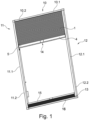
- the illustrated protective device for a roof window comprises a first protective element 1, which is designed as an insect screen pleated blind, and a second protective element 13, which is designed as a sun protection pleated blind.
- the first protective element 1 is assigned a strip unit 10 which has a profile strip 10.1 and a profile strip 10.2, wherein the profile strip 10.1 and the profile strip 10.2 are telescopic relative to one another.
- the first protective element 1 is also assigned a profile strip unit 14 which comprises a first profile strip 4 and a second profile strip 5 which is telescopic relative to the first profile strip 4.
- the second protective element 13 is assigned a strip unit 15 and a strip unit 16, which also each have two profile strips that can be telescoped towards one another.
- the protective device also comprises a guide rail unit 11 and a guide rail unit 12.
- the guide rail unit 11 comprises a guide rail 11.1 and a telescopic guide rail 11.2.
- the guide rail unit 12 comprises a guide rail 12.1 and a guide rail 12.2, which are telescopic towards each other.
- the guide rail units 11 and 12 When installed on a roof window, the guide rail units 11 and 12 are attached to the side edges of the window reveal, while the strip unit 10 and the strip unit 16 are fixed to an upper or lower edge of the window reveal.
- Invisible cords are assigned to the second protective element 13, the ends of which are at least indirectly fixed to the upper or lower edge of the window reveal. This is therefore a known pleated unit.
- the first protective element 1 is provided with a Figure 1 not shown cord 2, which comprises a cord drive system 3 which is arranged in the profile strip unit 14 and is further described below with reference to the other figures.
- the roof window opening When mounted on the roof window, the roof window opening can be closed/covered by the first protective element 1 and/or the second protective element 13.
- a user can pull the profile strip unit 14 downwards so that the building opening is covered by the protective element 1.
- a user can also pull the strip unit 15 upwards to cover the building opening by means of the second protective element 13.
- elements such as magnets or mechanical coupling elements can be provided so that the profile strip unit 14 and the strip unit 15 can be moved together.
- handle elements can be provided on the profile strip unit 14 and the strip unit 15. which have projection and recess designs in the form of hooks and receptacles so that they can mechanically lock together.
- at least one strip unit can be rotated about its longitudinal axis so that the previously existing form fit can be released.
- the profile strip unit 14, the strip unit 15 and the protective elements 1 and 13 are guided in the guide rail units 11.
- the protective device can be easily adapted to the height and width of the building opening by an end user before installation on a building opening.
- the strip units 10 and 16 are connected to the guide rail units 11 and 12 via plug connections, so that the guide rail units 11 and 12 as well as the (profile) strip units 10, 14, 15 and 16 can be made available to the user separately from one another.
- the length of the protective elements 1 and 13 can then be adapted by the user to the width of the building opening by cutting them to size.
- the protective element 1 has a so-called cordless guide system, in which a cord drive system is formed in the profile strip unit 14, which almost completely accommodates the cord 2, particularly in an open state. This prevents a cord of the second protective element 13 and the cord 2 of the first protective element 1 from having to be guided closely past one another. Such an obstruction of the cord systems is further reduced by the cord drive system 3 of the first protective element 1 being in the Guide rail units 11, 12 movable profile strip unit 14 and not in the strip unit 10. The profile strip unit 14 is thus arranged below the strip unit 10 and below the first protective element 1 in the assembled state.
- FIG 2 a perspective view of the profile strip unit 14 is shown, from which it can be seen that the first profile strip 4 and the second profile strip 5 are arranged telescopically relative to each other, wherein the profile strips 4, 5 each have a gap 4.1 and 5.1 through which the cord 2 of the in Figure 2 not clearly shown cord drive system 3.
- a connection to the first protective element 1 can also be established through the gap 5.1 or 4.1.
- corner connectors can be seen inserted into the profile strips 4 and 5, with which the profile strip unit 14 can be connected to the guide rail units 11 and 12.
- the cord drive system 3 comprises a spring element 7 designed as a helical spring, which is fixed on the one hand to a first end face 4.2 of the first profile strip 4 by means of a cap-like fastening element 17 and on the other hand is connected to a movable deflection unit 9 of the cord drive system 3.
- the movable deflection unit 9 is arranged displaceably in the first profile strip 4.
- the cord drive system 3 also comprises a stationary deflection unit 8, which is formed in one piece with the plug connection element for the guide rail unit 12.
- the stationary deflection unit 8 is thus arranged at an end of the first profile strip 4 associated with a second end face 4.3.
- both the immovable deflection unit 8 and the movable deflection unit 9 have four cord deflections 6 for the cord 2.
- the cord 2, the movable deflection unit 9 and the immovable deflection unit 8 thus form a type of pulley.
- the cord 2 is pulled out of the profile strip unit 14, whereby the movable deflection unit 9 is moved towards the immovable deflection unit 8 and the spring element 7 is tensioned.
- the profile strip unit 14 is returned upwards, the movable deflection unit 9 then moves away from the immovable deflection unit 8 due to the spring force provided by the spring element 7.
- the fastening element 17 securely fixes the spring element 7 in the first profile strip 4, but does not protrude beyond the outer contour of the first profile strip 4, the first profile strip 4 can be inserted as an inner profile strip into the second profile strip 5 designed as an outer profile strip. This means that a pleated blind system that can easily be changed in width can also be combined with a so-called cordless curtain system.
Landscapes
- Engineering & Computer Science (AREA)
- Structural Engineering (AREA)
- Architecture (AREA)
- Civil Engineering (AREA)
- Blinds (AREA)
Abstract
Description
- Die vorliegende Erfindung betrifft eine Schutzvorrichtung für eine Gebäudeöffnung, wie ein Dachfenster, und eine Gebäudeöffnung mit einer solchen Schutzvorrichtung. Die Schutzvorrichtung ist insbesondere als Insektenschutzvorrichtung oder Sonnenschutzvorrichtung ausgebildet und umfasst mindestens ein Schutzelement, wie ein Plissee oder mehrere Lamellen, mit denen die Gebäudeöffnung abgedeckt/verschlossen werden kann. Die Schutzvorrichtung umfasst ferner mindestens eine Schnur und ein Schnurantriebssystem, wobei das insbesondere mindestens ein Federelement aufweisende Schnurantriebssystem während des Verschließens und/oder Öffnens der Gebäudeöffnung mittels des mindestens einen Schutzelements betätigt wird. Die Schutzvorrichtung umfasst zudem eine zumindest eine erste Profilleiste aufweisende Profilleisteneinheit, in der das Schnurantriebssystem angeordnet ist.
- Die Erfindung betrifft insbesondere solche Schutzvorrichtungen, bei denen die Schnur vollständig in der ersten Profilleiste, dem mindestens einen Schutzelement und einer Leisteneinheit angeordnet ist, wobei das mindestens eine Schutzelement zwischen der ersten Profilleiste und der Leisteneinheit angeordnet ist und die erste Profilleiste und die Leisteneinheit zum Öffnen und/oder Verschließen des Gebäudes relativ zueinander bewegt werden. Bei solchen Schutzvorrichtungen muss die mindestens eine Schnur nicht gebäudeseitig, beispielsweise an einem die Gebäudeöffnung umgebenden Rahmen oder an einer die Gebäudeöffnung umgebenden Wand angebracht werden. Bei solchen missverständlicherweise auch als schnurlose Plisseeanordnungen bezeichneten Schutzvorrichtungen ist die das Schnurantriebssystem enthaltende erste Profilleiste im montierten Zustand oben an der Gebäudeöffnung angeordnet, so dass zum Betätigen der Schutzvorrichtung die Leisteneinheit runter und hoch bewegt wird.
- Wenn an der Gebäudeöffnung ein zweites Schutzelement angebracht werden soll, das beispielsweise zusätzlich zu einem als Insektenschutz ausgebildeten ersten Schutzelement als Sonnenschutz ausgebildet ist, so ist es für einen Anwender oft schwierig, die Schnüre der beiden Schutzvorrichtungen einfach und schnell zu installieren.
- Da bei den bekannten Schutzvorrichtungen das Schnurantriebssystem in der ersten Profilleiste der Profilleisteneinheit angeordnet ist, muss für unterschiedlich Breite Fenster jeweils eine entsprechend konfigurierte Schutzvorrichtung dem Endanwender zur Verfügung gestellt werden. Insbesondere wenn der Endanwender die Breite des Fensters selbst ausmisst, kann es hier zu Fehlkäufen kommen. Zudem muss der Anbieter eine Vielzahl von Schutzvorrichtungen mit unterschiedlicher Länge der nur eine Profilleiste aufweisenden Profilleisteneinheit bevorraten.
- Aufgabe der vorliegenden Erfindung ist es daher, die mit Bezug zum Stand der Technik geschilderten Nachteile zumindest teilweise zu beseitigen und insbesondere eine Schutzvorrichtung anzugeben, deren Breite einfach an unterschiedlich breite Fenster anpassbar ist.
- Eine Lösung für die Aufgabe ist mit der Schutzvorrichtung mit den Merkmalen des unabhängigen Anspruchs 1 angegeben. Weitere Lösungen und vorteilhafte Weiterbildungen sind in der vorstehenden und nachfolgenden Beschreibung sowie in den Unteransprüchen angegeben, wobei einzelne Merkmale der vorteilhaften Weiterbildung in technisch sinnvoller Weise miteinander kombinierbar sind.
- Die Aufgabe wird insbesondere gelöst durch eine Schutzvorrichtung für eine Gebäudeöffnung, welche insbesondere für ein Fenster und bevorzugt für ein Dachfenster ausgebildet ist, wobei die Schutzvorrichtung mindestens ein Schutzelement, wie beispielsweise ein Plissee (bevorzugt ein Insektenschutzplissee oder ein Sonnenschutzplissee) oder mehrere Lamellen, eine erste Profilleiste, mindestens eine Schnur und ein Schnurantriebssystem umfasst. Die Gebäudeöffnung ist mittels des mindestens einen Schutzelements abdeckbar, so dass im Falle eines Insektenschutzes keine Insekten durch die Gebäudeöffnung hindurchdringen können und im Falle eines Sonnenschutzes das Eindringen von Sonnenlicht minimiert oder vollständig unterbunden wird. Das insbesondere ein mechanisches Element zur Umlenkung der Schnur und zur Spannung der Schnur aufweisende Schnurantriebssystem ist in der ersten Profilleiste angeordnet und wird während des Verschließens und Öffnens der Gebäudeöffnung zumindest indirekt mittels des mindestens einen Schutzelements betätigt. Während des Verschließens und/oder Öffnens bewegen sich Elemente des Schnurantriebssystems.
- Es wird ferner vorgeschlagen, dass eine zweite Profilleiste vorgesehen ist, wobei die erste Profilleiste und die zweite Profilleiste zueinander teleskopierbar sind, wobei die so durch die erste Profilleiste und die zweite Profilleiste gebildete Profilleisteneinheit das Schnurantriebssystem umfasst. Hierbei kann vorgesehen sein, dass das Schnurantriebssystem abschnittsweise sowohl in der ersten als auch in der zweiten Profilleiste angeordnet ist. Bevorzugt ist jedoch, dass das Schnurantriebssystem ausschließlich in der ersten Profilleiste angeordnet ist. Durch Teleskopieren der ersten Profilleiste und der zweiten Profilleiste zueinander kann die Länge der aus der ersten Profilleiste und der mindestens einen zweiten Profilleiste bestehenden Profilleisteneinheit einfach an eine Breite eines Fensters angepasst werden. Der Anbieter einer solchen Schutzvorrichtung muss also nur eine Art von Schutzvorrichtung für unterschiedlich breite Fenster anbieten, während der Endbenutzer die Schutzvorrichtung während der Installation an die Breite des Fensters anpassen kann.
- Mit anderen Worten: Die Erfindung sieht in ihrem Grundgedanken vor, dass das Schnurantriebssystem in zumindest einem Element einer durch Teleskopieren in ihrer Länge veränderbaren Profilleisteneinheit angeordnet ist, wodurch die Schutzvorrichtung an unterschiedlich breite Gebäudeöffnungen einfach anpassbar ist.
- In einer Ausführungsform kann vorgesehen sein, dass die erste Profilleiste und die mindestens eine zweite Profilleiste der Profilleisteneinheit jeweils einen Spalt aufweisen, der sich entlang der jeweiligen Profilleiste erstreckt und dem mindestens einen Schutzelement zugewandt ist. Durch den jeweiligen Spalt kann eine von dem Schnurantriebssystem umgelenkte Schnur einfach hin zum Schutzelement und gegebenenfalls hin zu der Leisteneinheit geführt werden.
- In einer Ausführungsform kann vorgesehen sein, dass die erste Profilleiste und die mindestens eine zweite Profilleiste in einer Stellung zueinander fixierbar sind. Es kann beispielsweise ein in einer der Profilleisten ausgebildetes oder separates Fixierungselement vorgesehen sein, welches durch eine aktive Betätigung die Profilleisten in einer Stellung zueinander fixiert. Es kann beispielsweise ein Klemmelement oder eine Schraube vorgesehen sein, mit denen die Profilleisten zueinander fixiert werden.
- Das Schnurantriebssystem weist insbesondere mindestens ein Federelement auf. Das mindestens eine Federelement ist so ausgebildet und angeordnet, dass es während des Schließ-/Abdeckvorganges beispielsweise durch eine rotatorische oder lineare Bewegung gespannt wird. Das mindestens eine Federelement kann beispielsweise durch eine Spiralfeder ausgebildet sein. Bevorzugt ist das mindestens eine Federelement aber durch eine Art Schraubenzugfeder ausgebildet.
- Das Schnurantriebssystem umfasst zudem insbesondere eine oder mindestens zwei Schnurumlenkung(en), wobei die Schnurumlenkungen insbesondere so zueinander ausgerichtet und angeordnet sind, dass eine Art Flaschenzug ausgebildet wird. Bevorzugt sind mindestens vier Schnurumlenkungen ausgebildet, so dass die Schnur im geöffneten, also nicht abgedeckten, Zustand der Gebäudeöffnung in einer relativ zum Verstellweg der Schutzvorrichtung kurzen Profilleisteneinheit aufgenommen werden kann.
- Während es prinzipiell vorgesehen sein kann, dass die Schnur von dem Schnurantriebssystem auf- und abgewickelt wird, ist in einer bevorzugten Ausführungsform vorgesehen, dass das Schnurantriebssystem eine zu der ersten Profilleiste unbewegliche Umlenkeinheit mit mindestens einer, bevorzugt mindestens zwei, besonders bevorzugt mindestens vier oder genau vier Schnurumlenkung(en) und eine zu der ersten Profilleiste bewegliche Umlenkeinheit mit mindestens einer, bevorzugt mindestens zwei, besonders bevorzugt mindestens oder genau vier Schnurumlenkung(en) aufweist. Mit einem solchen Schnurantriebssystem kann ein kompaktes, ein Flaschenzugprinzip ausbildendes System bereitgestellt werden, mit welchem die Schnur auch auf engem Raum sicher, ohne mit sich selbst wechselzuwirken, geführt werden kann.
- In diesem Zusammenhang ist insbesondere bevorzugt, wenn das Federelement einerseits an einer ersten Stirnseite der ersten Profilleiste festgelegt ist und andererseits mit der beweglichen Umlenkeinheit verbunden ist, wobei die unbewegliche Umlenkeinheit an einer zweiten Stirnseite der ersten Profilleiste festgelegt ist. Auf diese Weise kann das Schnurantriebssystem einfach in der ersten Profilleiste installiert werden.
- Zur besonders einfachen Installation ist vorgesehen, dass an der ersten Stirnseite eine Art Kappe ausgebildet ist, die zumindest teilweise in die Profilleiste einsteckbar ist und an der das insbesondere als Schraubenzugfeder ausgebildete Federelement beispielsweise mit einem Haken eingreift. Die bewegliche Umlenkeinheit mit den insbesondere mehreren Schnurumlenkungen ist im Inneren der Profilleiste beweglich und mit dem insbesondere als Schraubenzugfeder ausgebildeten Federelement verbunden, wobei die Verbindung mit der beweglichen Umlenkeinheit ebenfalls über einen hakenartigen Eingriff des Federelements erfolgt. Für die insbesondere linear bewegliche Lagerung in der Profilleiste ist die Außenkontur der beweglichen Umlenkeinheit an die Innenkontur der Profilleiste angepasst.
- Die unbewegliche Umlenkeinheit ist bevorzugt als einteiliges Bauelement ausgebildet, welches auf der zweiten Stirnseite in die Profilleiste eingesteckt ist. An diesem Bauteil können weitere Elemente ausgebildet sein, über die die Schutzvorrichtung mit deren weiteren Bauteilen zusammengebaut werden kann.
- Die Schutzvorrichtung umfasst zudem bevorzugt eine Leisteneinheit, wobei das mindestens eine Schutzelement zwischen der Leisteneinheit einerseits und der ersten Profilleiste und der mindestens einen zweiten Profilleiste andererseits angeordnet ist. Die Leisteneinheit kann entweder als eine Griffeinheit dienen, an die der Benutzer angreift, wenn er die Schutzvorrichtung betätigen will. Wenn die Profilleisteneinheit beispielsweise im montierten Zustand ortsfest festgelegt ist, kann das erste Schutzelement durch Bedienen der Leisteneinheit betätigt werden. Wenn hingegen die Leisteneinheit im montierten Zustand ortsfest an der Gebäudeöffnung festgelegt, ist, kann das erste Schutzelement durch Betätigen der Profilleisteneinheit betätigt werden.
- Damit auch die Leisteneinheit an unterschiedlich breite Gebäudeöffnungen angepasst werden kann, ist in einer Ausführungsform vorgesehen, dass die Leisteneinheit mindestens zwei zueinander teleskopierbare Profilleisten umfasst.
- Es kann zudem vorgesehen sein, dass die Schnur mit ihren Enden in der Leisteneinheit festgelegt ist. Alternativ kann vorgesehen sein, dass die Schnur mit der Leisteneinheit umgelenkt wird.
- Um eine seitliche Führung für das mindestens eine Schutzelement vorzusehen, kann vorgesehen sein, dass die Schutzvorrichtung zwei Führungsschieneneinheiten aufweist, die jeweils im montierten Zustand rechtwinklig zu der die erste Profilleiste umfassenden Profilleisteneinheit ausgerichtet sind und in denen zumindest das mindestens eine Schutzelement während des Öffnens und Schließens geführt ist, wobei gegebenenfalls auch die Profilleisteneinheit oder die Leisteneinheit während ihrer Bewegung in der Führungsschieneneinheit geführt sind.
- Damit auch die Führungsschieneneinheiten in ihrer Länge an unterschiedlich hohe Gebäudeöffnungen einfach angepasst werden können, können die Führungsschieneneinheiten jeweils mindestens zwei zueinander teleskopierbare Führungsschienen aufweisen.
- Die Schutzvorrichtung betrifft insbesondere solche Ausführungen, bei denen zusätzlich zu dem mindestens einen Schutzelement ein weiteres, zweites Schutzelement vorgesehen ist, mit dem die Gebäudeöffnung abdeckbar ist.
- So kann beispielsweise vorgesehen sein, dass das mindestens eine erste Schutzelement einen Insektenschutz beispielsweise in Form eines Insektenschutzplissees und das mindestens eine zweite Schutzelement einen Sonnenschutz beispielsweise in Form eines Sonnenschutzplissees bereitstellt. Es kann dabei beispielsweise vorgesehen sein, dass die Gebäudeöffnung vollständig mittels des mindestens einen ersten Schutzelements oder mittels des mindestens einen zweiten Schutzelements abgedeckt wird. Es kann aber auch vorgesehen sein, dass ein Teil der Gebäudeöffnung mittels des mindestens einen ersten Schutzelements und der andere Teil der Gebäudeöffnung mittels des mindestens einen zweiten Schutzelements abgedeckt wird. So kann die Gebäudeöffnung beispielsweise teilweise mittels des Sonnenschutzelements abgedeckt werden, während der verbleibende Teil durch das Insektenschutzelement gegen das Eindringen von Insekten geschützt ist.
- Dem mindestens einen zweiten Schutzelement ist mindestens eine separate Schnur zugeordnet, welche in einer bevorzugten Ausführungsform mit ihren Enden ortsfest zu der Gebäudeöffnung festlegbar ist beziehungsweise festgelegt ist. Die Enden der Schnur sind insbesondere außerhalb der dem zweiten Schutzelement zugeordneten Leisteneinheiten an dem Rahmen der Gebäudeöffnung, einer die Gebäudeöffnung umgebender Laibung oder einem anderen Element der Schutzvorrichtung festgelegt oder festlegbar.
- Dem zweiten Schutzelement können zumindest zwei (weitere) Leisteneinheiten zugeordnet sein, zwischen denen das zweite Schutzelement angeordnet ist und durch welche insbesondere die mindestens eine dem zweiten Schutzelement zugeordnete Schnur hindurchgeführt ist. Diese weiteren Leisteneinheiten können jeweils mindestens zwei zueinander teleskopierbare Profilleisten umfassen, so dass auch die Leisteneinheiten des zweiten Schutzelements an eine Breite einer Gebäudeöffnung anpassbar sind.
- Bevorzugt ist zumindest eine dieser Leisteneinheiten ortsfest an der Gebäudeöffnung und insbesondere an einem unteren Ende der Gebäudeöffnung festgelegt, während die zweite Leisteneinheit dazu beweglich angeordnet ist.
- In einer besonders bevorzugten Ausführungsform ist die untere Leisteneinheit mit den Führungsschieneneinheiten verbunden, während die obere, bewegliche Leisteneinheit in den Führungsschieneneinheiten bei ihrer Bewegung geführt ist.
- Es kann in diesem Zusammenhang auch vorgesehen sein, dass die bewegliche Leisteneinheit des zweiten Schutzelements mit der beweglichen (Profil-) Leisteneinheit des ersten Schutzelements beispielsweise mechanisch oder magnetisch koppelbar ist, so dass die beweglichen (Profil-)Leisteneinheiten der unterschiedlichen Schutzelemente gleichzeitig bedienbar sind, ohne dass sich ein Spalt zwischen den beweglichen (Profil-)Leisteneinheiten ausbildet. Die beweglichen (Profil-)Leisteneinheiten sind dabei so aufeinander abgestimmt, dass kein Sonnenlicht oder keine Insekten zwischen ihnen hindurch durch die Gebäudeöffnung treten können.
- Wenn die beweglichen (Profil-)Leisteneinheiten mechanisch miteinander koppelbar sind, kann beispielsweise eine Art Hakenelement ausgebildet sein, welches in einer korrespondierenden Ausnehmung an der anderen (Profil-) Leisteneinheit eingreift. Zum Lösen dieser mechanischen Kopplung ist dann insbesondere vorgesehen, dass die eine Leisteneinheit um ihre Längsachse leicht rotiert wird, wodurch die zuvor bestehende formschlüssige Verbindung gelöst wird, so dass die beweglichen (Profil-)Leisteneinheiten unabhängig voneinander betätigt werden können.
- In einer bevorzugten Ausführungsform ist vorgesehen, dass die die erste Profilleiste und die mindestens eine zweite Profilleiste umfassende Profilleisteneinheit im montierten Zustand der Schutzvorrichtung unterhalb des mindestens einen Schutzelements und damit auch unterhalb der bevorzugt vorgesehenen Leisteneinheit entlang der Gebäudeöffnung mit einer vertikalen Komponente beweglich ist.
- Die Erfindung sowie das technische Umfeld werden im Folgenden beispielhaft anhand der Figuren erläutert. Es zeigen schematisch
- Figur 1:
- eine Schutzvorrichtung,
- Figur 2:
- eine Profilleisteneinheit der Schutzvorrichtung,
- Figur 3:
- ein Schnurantriebssystem in einer teilweise transparent dargestellten ersten Profilleiste der Profilleisteneinheit,
- Figur 4:
- das Schnurantriebssystem und
- Figur 5:
- Umlenkeinheiten und die Schnur des Schnurantriebssystems.
- Die in
Figur 1 dargestellte Schutzvorrichtung für ein Dachfenster umfasst ein erstens Schutzelement 1, welches als Insektenschutzplissee ausgebildet ist, und ein zweites Schutzelement 13, welches als Sonnenschutzplissee ausgebildet ist. - Dem ersten Schutzelement 1 ist eine Leisteneinheit 10 zugeordnet, die eine Profilleiste 10.1 und eine Profilleiste 10.2 aufweist, wobei die Profilleiste 10.1 und die Profilleiste 10.2 teleskopierbar zueinander sind. Dem ersten Schutzelement 1 ist zudem eine Profilleisteneinheit 14 zugeordnet, die eine erste Profilleiste 4 und eine zu der ersten Profilleiste 4 teleskopierbare zweite Profilleiste 5 umfasst.
- Dem zweiten Schutzelement 13 ist eine Leisteneinheit 15 und eine Leisteneinheit 16 zugeordnet, die ebenfalls jeweils zwei zueinander teleskopierbare Profilleisten aufweisen.
- Die Schutzvorrichtung umfasst zudem eine Führungsschieneneinheit 11 und eine Führungsschieneneinheit 12. Die Führungsschieneneinheit 11 umfasst eine Führungsschiene 11.1 und eine dazu teleskopierbare Führungsschiene 11.2. Die Führungsschieneneinheit 12 umfasst eine Führungsschiene 12.1 und eine Führungsschiene 12.2, die zueinander teleskopierbar sind.
- In einem an einem Dachfenster installierten Zustand sind die Führungsschieneneinheiten 11 und 12 an seitlichen Rändern der Fensterlaibung angebracht, während die Leisteneinheit 10 und die Leisteneinheit 16 an einem oberen bzw. unteren Rand der Fensterlaibung ortsfest angebracht sind. Dem zweiten Schutzelement 13 sind nicht sichtbare Schnüre zugeordnet, deren Enden am oberen bzw. unteren Rand der Fensterlaibung zumindest indirekt fixiert sind. Es handelt sich also um eine an sich bekannte Plisseeeinheit.
- Dem ersten Schutzelement 1 ist hingegen eine in der
Figur 1 nicht dargestellte Schnur 2 zugeordnet, die ein Schnurantriebssystem 3 umfasst, welches in der Profilleisteneinheit 14 angeordnet ist und mit Bezug zu den übrigen Figuren im Folgenden weiter beschrieben wird. - Im am Dachfenster montierten Zustand kann die Dachfensteröffnung durch das erste Schutzelement 1 und/oder das zweite Schutzelement 13 verschlossen/abgedeckt werden. So kann beispielsweise ein Benutzer die Profilleisteneinheit 14 nach unten ziehen, so dass die Gebäudeöffnung durch das Schutzelement 1 abgedeckt wird. Ein Benutzer kann aber auch die Leisteneinheit 15 nach oben ziehen, um die Gebäudeöffnung mittels des zweiten Schutzelements 13 abzudecken. Es besteht auch die Möglichkeit, den oberen Teil der Gebäudeöffnung mittels des Schutzelements 1 und den unteren Teil der Gebäudeöffnung mittels des Schutzelements 13 zu verdecken, in welchem Fall die Profilleisteneinheit 14 und die Leisteneinheit 15 aneinander anliegen. Um die Profilleisteneinheit 14 mit der Leisteneinheit 15 zu koppeln, können Elemente wie beispielsweise Magnete oder mechanische Kopplungselemente vorgesehen sein, so dass die Profilleisteneinheit 14 und die Leisteneinheit 15 gemeinsam bewegt werden können. Insbesondere können an der Profilleisteneinheit 14 und der Leisteneinheit 15 Griffelemente angebracht sein, die Vorsprungs- und Rücksprunggestaltungen in Form von Haken und Aufnahmen aufweisen, so dass sie mechanisch miteinander verrasten können. Um diese Verrastung zu lösen, kann zumindest eine Leisteneinheit um ihre Längsachse rotiert werden, so dass der zuvor bestandene Formschluss gelöst werden kann.
- Während des Verschließens oder Öffnens der Gebäudeöffnung sind die Profilleisteneinheit 14, die Leisteneinheit 15 sowie die Schutzelemente 1 und 13 in den Führungsschieneneinheiten 11 geführt.
- Durch die Teleskopierbarkeit der Führungsschienen 11.1, 11.2 bzw. 12.1 und 12.2 sowie der Profilleisten der (Profil-)Leisteneinheiten 10, 14, 15 und 16 kann die Schutzvorrichtung von einem Endanwender vor der Installation an einer Gebäudeöffnung einfach an die Höhe und Breite der Gebäudeöffnung angepasst werden. Hierbei kann insbesondere vorgesehen sein, dass die Leisteneinheiten 10 und 16 über Steckverbindungen mit den Führungsschieneneinheiten 11 und 12 verbunden werden, so dass die Führungsschieneneinheiten 11 und 12 sowie die (Profil-)Leisteneinheiten 10, 14, 15 und 16 getrennt voneinander dem Benutzer bereitgestellt werden können. Die Länge der Schutzelemente 1 und 13 kann dann von dem Benutzer an die Breite der Gebäudeöffnung durch Zuschneiden angepasst werden.
- Während die Schnüre des zweiten Schutzelements 13 beispielsweise in den Führungsschieneneinheiten 11 und 12 verlegt sein können, weist das Schutzelement 1 ein sogenanntes schnurloses Führungssystem auf, bei dem in der Profilleisteneinheit 14 ein Schnurantriebssystem ausgebildet ist, das die Schnur 2 insbesondere in einem geöffneten Zustand fast vollständig aufnimmt. Somit wird verhindert, dass eine Schnur des zweiten Schutzelements 13 mit der Schnur 2 des ersten Schutzelements 1 aneinander eng vorbeigeführt werden müssen. Eine solche Behinderung der Schnursysteme wird noch dadurch weiter reduziert, dass das Schnurantriebssystem 3 des ersten Schutzelements 1 in der zu den Führungsschieneneinheiten 11, 12 beweglichen Profilleisteneinheit 14 und nicht in der Leisteneinheit 10 angeordnet ist. Die Profilleisteneinheit 14 ist somit unterhalb der Leisteneinheit 10 und unterhalb des ersten Schutzelements 1 im montierten Zustand angeordnet.
- In
Figur 2 ist eine Perspektivansicht der Profilleisteneinheit 14 dargestellt, aus der erkennbar ist, dass die erste Profilleiste 4 und die zweite Profilleiste 5 teleskopierbar zueinander angeordnet sind, wobei die Profilleisten 4, 5 jeweils einen Spalt 4.1 und 5.1 aufweisen, durch welchen hindurch die Schnur 2 des inFigur 2 nicht deutlich gezeigten Schnurantriebssystems 3 hindurchgeführt werden kann. Durch den Spalt 5.1 bzw. 4.1 kann auch eine Verbindung zu dem ersten Schutzelement 1 hergestellt werden. - An den Enden der Profilleisteneinheit 14 sind in die Profilleisten 4 bzw. 5 eingesteckte Eckverbinder zu erkennen, mit denen die Profilleisteneinheit 14 mit den Führungsschieneneinheiten 11 bzw. 12 verbunden werden kann.
- In den
Figuren 3 und 4 ist das Schnurantriebssystem 3 dargestellt, wobei inFigur 3 die erste Profilleiste 4 in einem teilweise transparenten Zustand dargestellt ist. - Das Schnurantriebssystem 3 umfasst ein als Schraubenfeder ausgebildetes Federelement 7, welches einerseits an einer ersten Stirnseite 4.2 der ersten Profilleiste 4 mittels eines kappenartigen Befestigungselements 17 festgelegt ist und andererseits mit einer beweglichen Umlenkeinheit 9 des Schnurantriebssystems 3 verbunden ist. Die bewegliche Umlenkeinheit 9 ist verschiebbar in der ersten Profilleiste 4 angeordnet.
- Das Schnurantriebssystem 3 umfasst zudem eine unbewegliche Umlenkeinheit 8, die einteilig mit dem Steckverbindungselement für die Führungsschieneneinheit 12 ausgebildet ist. Die unbewegliche Umlenkeinheit 8 ist somit an einem einer zweiten Stirnseite 4.3 zugeordneten Ende der ersten Profilleiste 4 angeordnet.
- Wie insbesondere aus
Figur 5 hervorgeht, weist sowohl die unbewegliche Umlenkeinheit 8 als auch die bewegliche Umlenkeinheit 9 vier Schnurumlenkungen 6 für die Schnur 2 auf. Die Schnur 2, die bewegliche Umlenkeinheit 9 und die unbewegliche Umlenkeinheit 8 bilden somit eine Art Flaschenzug aus. Während des Verschließens der Gebäudeöffnung mittels des ersten Schutzelements 1 wird die Schnur 2 aus der Profilleisteneinheit 14 herausgezogen, wobei die bewegliche Umlenkeinheit 9 auf die unbewegliche Umlenkeinheit 8 zubewegt wird und das Federelement 7 gespannt wird. Beim Zurückführen der Profilleisteneinheit 14 nach oben bewegt sich dann die bewegliche Umlenkeinheit 9 aufgrund der von dem Federelement 7 bereitgestellten Federkraft von der unbeweglichen Umlenkeinheit 8 fort. - Da das Befestigungselement 17 das Federelement 7 sicher in der ersten Profilleiste 4 fixiert, aber nicht über die äußere Kontur der ersten Profilleiste 4 hervorsteht, kann die erste Profilleiste 4 als Innenprofilleiste in die als Außenprofilleiste ausgebildete zweite Profilleiste 5 eingeschoben werden. Somit kann auch ein einfach in seiner Breite veränderbares Plisseesystem mit einem sogenannten schnurlosen Vorhangsystem kombiniert werden.
-
- 1
- Schutzelement
- 2
- Schnur
- 3
- Schnurantriebssystem
- 4
- erste Profilleiste
- 4.1
- Spalt
- 4.2
- erste Stirnseite
- 4.3
- zweite Stirnseite
- 5
- zweite Profilleiste
- 5.1
- Spalt
- 6
- Schnurumlenkung
- 7
- Federelement
- 8
- unbewegliche Umlenkeinheit
- 9
- bewegliche Umlenkeinheit
- 10
- Leisteneinheit
- 10.1
- Profilleiste
- 10.2
- Profilleiste
- 11
- Führungsschieneneinheit
- 11.1
- Führungsschiene
- 11.2
- Führungsschiene
- 12
- Führungsschieneneinheit
- 12.1
- Führungsschiene
- 12.2
- Führungsschiene
- 13
- zweites Schutzelement
- 14
- Profilleisteneinheit
- 15
- Leisteneinheit des zweiten Schutzelements
- 16
- Leisteneinheit des zweiten Schutzelements
- 17
- Befestigungselement
Claims (15)
- Schutzvorrichtung für eine Gebäudeöffnung, umfassend- mindestens ein Schutzelement (1),- eine erste Profilleiste (4),- mindestens eine Schnur (2),- ein Schnurantriebssystem (3), wobeidadurch gekennzeichnet, dass• die Gebäudeöffnung mittels des mindestens einen Schutzelements (1) abdeckbar ist,• das Schnurantriebssystem (3) während des Schließens und/oder Öffnens der Gebäudeöffnung mittels des mindestens einen Schutzelements (1) betätigt wird und• das Schnurantriebsystem (3) in der ersten Profilleiste (4) angeordnet ist,
mindestens eine zweite Profilleiste (5) vorgesehen ist, wobei die erste Profilleiste (4) und die zweite Profilleiste (5) zueinander teleskopierbar sind. - Schutzvorrichtung nach Anspruch 1, wobei die erste Profilleiste (4) und die mindestens eine zweite Profilleiste (5) jeweils einen Spalt (4.1, 5.1) aufweisen, wobei sich der Spalt (4.1, 5.1) entlang der Profilleiste (4, 5) erstreckt und dem mindestens einen Schutzelement (1) zugewandt ist.
- Schutzvorrichtung nach Anspruch 1 oder 2, wobei die erste Profilleiste (4) und die mindestens eine zweite Profilleiste (5) in einer Stellung zueinander fixierbar sind.
- Schutzvorrichtung nach einem der vorhergehenden Ansprüche, wobei das Schnurantriebssystem (3) mindestens zwei Schnurumlenkungen (6) und mindestens ein Federelement (7) umfasst.
- Schutzvorrichtung nach einem der vorhergehenden Ansprüche, wobei das Schnurantriebssystem (3) eine zu der ersten Profilleiste (4) unbewegliche Umlenkeinheit (8) mit mindestens einer Schnurumlenkung (6) und eine zu der ersten Profilleiste (4) bewegliche Umlenkeinheit (9) mit mindestens einer Schnurumlenkung (6) aufweist.
- Schutzvorrichtung nach Anspruch 4 und 5, wobei das Federelement (7) einerseits an einer ersten Stirnseite (4.2) der ersten Profilleiste (4) festgelegt ist und andererseits mit der beweglichen Umlenkeinheit (9) verbunden ist, wobei die unbewegliche Umlenkeinheit (8) an einer zweiten Stirnseite (4.3) der ersten Profilleiste (4) festgelegt ist.
- Schutzvorrichtung nach einem der vorhergehenden Ansprüche, wobei das mindestens eine Schutzelement (1) ein Element der folgenden Gruppe umfasst:- ein Plissee, insbesondere ein Insektenschutzplissee oder ein Sonnenschutzplissee,- mehrere Lamellen.
- Schutzvorrichtung nach einem der vorhergehenden Ansprüche, umfassend eine Leisteneinheit (10), wobei das mindestens eine Schutzelement (1) zwischen der Leisteneinheit (10) einerseits und der ersten Profilleiste (4) und der mindestens einen zweiten Profilleiste (5) andererseits angeordnet ist.
- Schutzvorrichtung nach Anspruch 8, wobei die Leisteneinheit (10) mindestens zwei zueinander teleskopierbare Profilleisten (10.1, 10.2) umfasst.
- Schutzvorrichtung nach Anspruch 8 oder 9, wobei die mindestens eine Schnur (2) mit der Leisteneinheit (10) umgelenkt wird.
- Schutzvorrichtung nach einem der vorhergehenden Ansprüche, umfassend zwei Führungsschieneneinheiten (11, 12), die jeweils rechtwinklig zu der ersten Profilleiste (4) ausgerichtet sind und in denen das mindestens eine Schutzelement (1) während des Öffnens und Schließens geführt ist.
- Schutzvorrichtung nach Anspruch 11, wobei die Führungsschieneneinheiten (11, 12) jeweils zwei zueinander teleskopierbare Führungsschienen (11.1, 11.2, 12.1, 12.2) aufweisen.
- Schutzvorrichtung nach einem der vorhergehenden Ansprüche, umfassend mindestens ein zweites Schutzelement (13), wobei die Gebäudeöffnung mittels des mindestens einen Schutzelements (1) und/oder mittels des mindestens einen zweiten Schutzelements (13) abdeckbar ist.
- Schutzvorrichtung nach Anspruch 13, wobei das eine Schutzelement (1) ein Insektenschutzplissee und das andere Schutzelement (13) ein Sonnenschutzplissee ist.
- Gebäudeöffnung, insbesondere Dachfenster, mit mindestens einer Schutzvorrichtung nach einem der Ansprüche 1 bis 14, wobei die erste Profilleiste (4) und die mindestens eine zweite Profilleiste (5) unterhalb des mindestens einen Schutzelements (1) entlang der Gebäudeöffnung mit einer vertikalen Komponente beweglich ist.
Priority Applications (1)
| Application Number | Priority Date | Filing Date | Title |
|---|---|---|---|
| EP23178390.3A EP4474610B1 (de) | 2023-06-09 | 2023-06-09 | Schutzvorrichtung für eine gebäudeöffnung und gebäudeöffnung mit einer solchen schutzvorrichtung |
Applications Claiming Priority (1)
| Application Number | Priority Date | Filing Date | Title |
|---|---|---|---|
| EP23178390.3A EP4474610B1 (de) | 2023-06-09 | 2023-06-09 | Schutzvorrichtung für eine gebäudeöffnung und gebäudeöffnung mit einer solchen schutzvorrichtung |
Publications (3)
| Publication Number | Publication Date |
|---|---|
| EP4474610A1 true EP4474610A1 (de) | 2024-12-11 |
| EP4474610B1 EP4474610B1 (de) | 2026-03-18 |
| EP4474610C0 EP4474610C0 (de) | 2026-03-18 |
Family
ID=86760458
Family Applications (1)
| Application Number | Title | Priority Date | Filing Date |
|---|---|---|---|
| EP23178390.3A Active EP4474610B1 (de) | 2023-06-09 | 2023-06-09 | Schutzvorrichtung für eine gebäudeöffnung und gebäudeöffnung mit einer solchen schutzvorrichtung |
Country Status (1)
| Country | Link |
|---|---|
| EP (1) | EP4474610B1 (de) |
Citations (2)
| Publication number | Priority date | Publication date | Assignee | Title |
|---|---|---|---|---|
| US20050194107A1 (en) * | 2004-03-05 | 2005-09-08 | Ming Nien | Retractable slat and window blind using same |
| US20090173459A1 (en) * | 2006-09-14 | 2009-07-09 | Sheng Ying Hsu | Curtain assembly |
-
2023
- 2023-06-09 EP EP23178390.3A patent/EP4474610B1/de active Active
Patent Citations (2)
| Publication number | Priority date | Publication date | Assignee | Title |
|---|---|---|---|---|
| US20050194107A1 (en) * | 2004-03-05 | 2005-09-08 | Ming Nien | Retractable slat and window blind using same |
| US20090173459A1 (en) * | 2006-09-14 | 2009-07-09 | Sheng Ying Hsu | Curtain assembly |
Also Published As
| Publication number | Publication date |
|---|---|
| EP4474610B1 (de) | 2026-03-18 |
| EP4474610C0 (de) | 2026-03-18 |
Similar Documents
| Publication | Publication Date | Title |
|---|---|---|
| DE3878816T2 (de) | Vertikale sonnenschutzvorrichtung. | |
| DE3521084C2 (de) | ||
| EP0040800A1 (de) | Rolladen | |
| DE60037214T2 (de) | Abschirmvorrichtung für ein Fenster und Bremseinrichtung hierfür | |
| DE202022106449U1 (de) | Horizontal-Jalousie mit verdeckter Spannschnur | |
| EP1681435B1 (de) | Sonnenschutzanlage mit Notraffvorrichtung | |
| DE102009011914A1 (de) | Plisseesystem | |
| EP3655612B1 (de) | Plisseejalousie mit teleskopierbarer führungsschiene | |
| DE102013111815A1 (de) | Plisseejalousie | |
| EP4474610B1 (de) | Schutzvorrichtung für eine gebäudeöffnung und gebäudeöffnung mit einer solchen schutzvorrichtung | |
| DE2527880A1 (de) | Vorrichtung zur sicherung von rollaeden | |
| EP4474611A1 (de) | Gebäudeöffnung mit einer schutzvorrichtung | |
| EP3173569B1 (de) | Schutzvorrichtung | |
| DE3048333C2 (de) | Halterungsvorrichtung für ein Springrollo | |
| DE202018103057U1 (de) | Plisseejalousie | |
| DE102018104138A1 (de) | Einlauftrichtereinrichtung und Beschattungskasten mit einer Einlauftrichtereinrichtung | |
| DE69203182T2 (de) | Sperrvorrichtung für Rolltoren. | |
| DE3037703C2 (de) | Lemellenjalousie mit einem raffbaren Lamellenbehang mit verschwenkbaren Lamellen | |
| EP1455047B1 (de) | Einlauftrichter | |
| EP0267303B1 (de) | Fussteil für eine Seitenführung | |
| DE202014004170U1 (de) | Schutzrollo für eine Fenster- oder Türöffnung | |
| DE9411037U1 (de) | Sicherheitstür | |
| DE102006026757B4 (de) | Fahrzeugfenster-Jalousieanordnung | |
| DE10050176B4 (de) | Einrastbare Führungsschiene | |
| DE8517182U1 (de) | Rolladen |
Legal Events
| Date | Code | Title | Description |
|---|---|---|---|
| PUAI | Public reference made under article 153(3) epc to a published international application that has entered the european phase |
Free format text: ORIGINAL CODE: 0009012 |
|
| STAA | Information on the status of an ep patent application or granted ep patent |
Free format text: STATUS: THE APPLICATION HAS BEEN PUBLISHED |
|
| AK | Designated contracting states |
Kind code of ref document: A1 Designated state(s): AL AT BE BG CH CY CZ DE DK EE ES FI FR GB GR HR HU IE IS IT LI LT LU LV MC ME MK MT NL NO PL PT RO RS SE SI SK SM TR |
|
| STAA | Information on the status of an ep patent application or granted ep patent |
Free format text: STATUS: REQUEST FOR EXAMINATION WAS MADE |
|
| 17P | Request for examination filed |
Effective date: 20250331 |
|
| GRAP | Despatch of communication of intention to grant a patent |
Free format text: ORIGINAL CODE: EPIDOSNIGR1 |
|
| STAA | Information on the status of an ep patent application or granted ep patent |
Free format text: STATUS: GRANT OF PATENT IS INTENDED |
|
| INTG | Intention to grant announced |
Effective date: 20251008 |
|
| RIN1 | Information on inventor provided before grant (corrected) |
Inventor name: WEIGL, ROBERT Inventor name: AULERT, HARALD Inventor name: GINSBERG, STEFFEN Inventor name: PIKIS, WIDAS Inventor name: VAN LEEUWEN, RITSKE |
|
| GRAS | Grant fee paid |
Free format text: ORIGINAL CODE: EPIDOSNIGR3 |
|
| GRAA | (expected) grant |
Free format text: ORIGINAL CODE: 0009210 |
|
| STAA | Information on the status of an ep patent application or granted ep patent |
Free format text: STATUS: THE PATENT HAS BEEN GRANTED |
|
| AK | Designated contracting states |
Kind code of ref document: B1 Designated state(s): AL AT BE BG CH CY CZ DE DK EE ES FI FR GB GR HR HU IE IS IT LI LT LU LV MC ME MK MT NL NO PL PT RO RS SE SI SK SM TR |
|
| REG | Reference to a national code |
Ref country code: CH Ref legal event code: F10 Free format text: ST27 STATUS EVENT CODE: U-0-0-F10-F00 (AS PROVIDED BY THE NATIONAL OFFICE) Effective date: 20260318 Ref country code: GB Ref legal event code: FG4D Free format text: NOT ENGLISH |
|
| REG | Reference to a national code |
Ref country code: DE Ref legal event code: R096 Ref document number: 502023003395 Country of ref document: DE |
|
| REG | Reference to a national code |
Ref country code: IE Ref legal event code: FG4D Free format text: LANGUAGE OF EP DOCUMENT: GERMAN |
|
| U01 | Request for unitary effect filed |
Effective date: 20260402 |