EP4474000A1 - Aufsteck- und sicherungsvorrichtung des rotors einer peristaltischen blutpumpe - Google Patents
Aufsteck- und sicherungsvorrichtung des rotors einer peristaltischen blutpumpe Download PDFInfo
- Publication number
- EP4474000A1 EP4474000A1 EP24179561.6A EP24179561A EP4474000A1 EP 4474000 A1 EP4474000 A1 EP 4474000A1 EP 24179561 A EP24179561 A EP 24179561A EP 4474000 A1 EP4474000 A1 EP 4474000A1
- Authority
- EP
- European Patent Office
- Prior art keywords
- drive shaft
- section
- rotor
- groove
- central axis
- Prior art date
- Legal status (The legal status is an assumption and is not a legal conclusion. Google has not performed a legal analysis and makes no representation as to the accuracy of the status listed.)
- Granted
Links
Images
Classifications
-
- A—HUMAN NECESSITIES
- A61—MEDICAL OR VETERINARY SCIENCE; HYGIENE
- A61M—DEVICES FOR INTRODUCING MEDIA INTO, OR ONTO, THE BODY; DEVICES FOR TRANSDUCING BODY MEDIA OR FOR TAKING MEDIA FROM THE BODY; DEVICES FOR PRODUCING OR ENDING SLEEP OR STUPOR
- A61M60/00—Blood pumps; Devices for mechanical circulatory actuation; Balloon pumps for circulatory assistance
- A61M60/10—Location thereof with respect to the patient's body
- A61M60/104—Extracorporeal pumps, i.e. the blood being pumped outside the patient's body
- A61M60/109—Extracorporeal pumps, i.e. the blood being pumped outside the patient's body incorporated within extracorporeal blood circuits or systems
- A61M60/113—Extracorporeal pumps, i.e. the blood being pumped outside the patient's body incorporated within extracorporeal blood circuits or systems in other functional devices, e.g. dialysers or heart-lung machines
-
- A—HUMAN NECESSITIES
- A61—MEDICAL OR VETERINARY SCIENCE; HYGIENE
- A61M—DEVICES FOR INTRODUCING MEDIA INTO, OR ONTO, THE BODY; DEVICES FOR TRANSDUCING BODY MEDIA OR FOR TAKING MEDIA FROM THE BODY; DEVICES FOR PRODUCING OR ENDING SLEEP OR STUPOR
- A61M5/00—Devices for bringing media into the body in a subcutaneous, intra-vascular or intramuscular way; Accessories therefor, e.g. filling or cleaning devices, arm-rests
- A61M5/14—Infusion devices, e.g. infusing by gravity; Blood infusion; Accessories therefor
- A61M5/142—Pressure infusion, e.g. using pumps
- A61M5/14212—Pumping with an aspiration and an expulsion action
- A61M5/14228—Pumping with an aspiration and an expulsion action with linear peristaltic action, i.e. comprising at least three pressurising members or a helical member
-
- A—HUMAN NECESSITIES
- A61—MEDICAL OR VETERINARY SCIENCE; HYGIENE
- A61M—DEVICES FOR INTRODUCING MEDIA INTO, OR ONTO, THE BODY; DEVICES FOR TRANSDUCING BODY MEDIA OR FOR TAKING MEDIA FROM THE BODY; DEVICES FOR PRODUCING OR ENDING SLEEP OR STUPOR
- A61M60/00—Blood pumps; Devices for mechanical circulatory actuation; Balloon pumps for circulatory assistance
- A61M60/10—Location thereof with respect to the patient's body
- A61M60/104—Extracorporeal pumps, i.e. the blood being pumped outside the patient's body
- A61M60/109—Extracorporeal pumps, i.e. the blood being pumped outside the patient's body incorporated within extracorporeal blood circuits or systems
-
- A—HUMAN NECESSITIES
- A61—MEDICAL OR VETERINARY SCIENCE; HYGIENE
- A61M—DEVICES FOR INTRODUCING MEDIA INTO, OR ONTO, THE BODY; DEVICES FOR TRANSDUCING BODY MEDIA OR FOR TAKING MEDIA FROM THE BODY; DEVICES FOR PRODUCING OR ENDING SLEEP OR STUPOR
- A61M1/00—Suction or pumping devices for medical purposes; Devices for carrying-off, for treatment of, or for carrying-over, body-liquids; Drainage systems
- A61M1/14—Dialysis systems; Artificial kidneys; Blood oxygenators ; Reciprocating systems for treatment of body fluids, e.g. single needle systems for hemofiltration or pheresis
- A61M1/16—Dialysis systems; Artificial kidneys; Blood oxygenators ; Reciprocating systems for treatment of body fluids, e.g. single needle systems for hemofiltration or pheresis with membranes
- A61M1/1621—Constructional aspects thereof
-
- A—HUMAN NECESSITIES
- A61—MEDICAL OR VETERINARY SCIENCE; HYGIENE
- A61M—DEVICES FOR INTRODUCING MEDIA INTO, OR ONTO, THE BODY; DEVICES FOR TRANSDUCING BODY MEDIA OR FOR TAKING MEDIA FROM THE BODY; DEVICES FOR PRODUCING OR ENDING SLEEP OR STUPOR
- A61M1/00—Suction or pumping devices for medical purposes; Devices for carrying-off, for treatment of, or for carrying-over, body-liquids; Drainage systems
- A61M1/36—Other treatment of blood in a by-pass of the natural circulatory system, e.g. temperature adaptation, irradiation ; Extra-corporeal blood circuits
- A61M1/3621—Extra-corporeal blood circuits
-
- A—HUMAN NECESSITIES
- A61—MEDICAL OR VETERINARY SCIENCE; HYGIENE
- A61M—DEVICES FOR INTRODUCING MEDIA INTO, OR ONTO, THE BODY; DEVICES FOR TRANSDUCING BODY MEDIA OR FOR TAKING MEDIA FROM THE BODY; DEVICES FOR PRODUCING OR ENDING SLEEP OR STUPOR
- A61M1/00—Suction or pumping devices for medical purposes; Devices for carrying-off, for treatment of, or for carrying-over, body-liquids; Drainage systems
- A61M1/36—Other treatment of blood in a by-pass of the natural circulatory system, e.g. temperature adaptation, irradiation ; Extra-corporeal blood circuits
- A61M1/3621—Extra-corporeal blood circuits
- A61M1/3622—Extra-corporeal blood circuits with a cassette forming partially or totally the blood circuit
- A61M1/36225—Extra-corporeal blood circuits with a cassette forming partially or totally the blood circuit with blood pumping means or components thereof
-
- A—HUMAN NECESSITIES
- A61—MEDICAL OR VETERINARY SCIENCE; HYGIENE
- A61M—DEVICES FOR INTRODUCING MEDIA INTO, OR ONTO, THE BODY; DEVICES FOR TRANSDUCING BODY MEDIA OR FOR TAKING MEDIA FROM THE BODY; DEVICES FOR PRODUCING OR ENDING SLEEP OR STUPOR
- A61M60/00—Blood pumps; Devices for mechanical circulatory actuation; Balloon pumps for circulatory assistance
- A61M60/20—Type thereof
- A61M60/247—Positive displacement blood pumps
- A61M60/253—Positive displacement blood pumps including a displacement member directly acting on the blood
- A61M60/268—Positive displacement blood pumps including a displacement member directly acting on the blood the displacement member being flexible, e.g. membranes, diaphragms or bladders
- A61M60/279—Peristaltic pumps, e.g. roller pumps
-
- A—HUMAN NECESSITIES
- A61—MEDICAL OR VETERINARY SCIENCE; HYGIENE
- A61M—DEVICES FOR INTRODUCING MEDIA INTO, OR ONTO, THE BODY; DEVICES FOR TRANSDUCING BODY MEDIA OR FOR TAKING MEDIA FROM THE BODY; DEVICES FOR PRODUCING OR ENDING SLEEP OR STUPOR
- A61M60/00—Blood pumps; Devices for mechanical circulatory actuation; Balloon pumps for circulatory assistance
- A61M60/30—Medical purposes thereof other than the enhancement of the cardiac output
- A61M60/36—Medical purposes thereof other than the enhancement of the cardiac output for specific blood treatment; for specific therapy
- A61M60/38—Blood oxygenation
-
- A—HUMAN NECESSITIES
- A61—MEDICAL OR VETERINARY SCIENCE; HYGIENE
- A61M—DEVICES FOR INTRODUCING MEDIA INTO, OR ONTO, THE BODY; DEVICES FOR TRANSDUCING BODY MEDIA OR FOR TAKING MEDIA FROM THE BODY; DEVICES FOR PRODUCING OR ENDING SLEEP OR STUPOR
- A61M60/00—Blood pumps; Devices for mechanical circulatory actuation; Balloon pumps for circulatory assistance
- A61M60/40—Details relating to driving
- A61M60/424—Details relating to driving for positive displacement blood pumps
- A61M60/438—Details relating to driving for positive displacement blood pumps the force acting on the blood contacting member being mechanical
- A61M60/441—Details relating to driving for positive displacement blood pumps the force acting on the blood contacting member being mechanical generated by an electromotor
-
- A—HUMAN NECESSITIES
- A61—MEDICAL OR VETERINARY SCIENCE; HYGIENE
- A61M—DEVICES FOR INTRODUCING MEDIA INTO, OR ONTO, THE BODY; DEVICES FOR TRANSDUCING BODY MEDIA OR FOR TAKING MEDIA FROM THE BODY; DEVICES FOR PRODUCING OR ENDING SLEEP OR STUPOR
- A61M60/00—Blood pumps; Devices for mechanical circulatory actuation; Balloon pumps for circulatory assistance
- A61M60/80—Constructional details other than related to driving
- A61M60/835—Constructional details other than related to driving of positive displacement blood pumps
-
- F—MECHANICAL ENGINEERING; LIGHTING; HEATING; WEAPONS; BLASTING
- F04—POSITIVE - DISPLACEMENT MACHINES FOR LIQUIDS; PUMPS FOR LIQUIDS OR ELASTIC FLUIDS
- F04B—POSITIVE-DISPLACEMENT MACHINES FOR LIQUIDS; PUMPS
- F04B43/00—Machines, pumps, or pumping installations having flexible working members
- F04B43/12—Machines, pumps, or pumping installations having flexible working members having peristaltic action
- F04B43/1253—Machines, pumps, or pumping installations having flexible working members having peristaltic action by using two or more rollers as squeezing elements, the rollers moving on an arc of a circle during squeezing
-
- F—MECHANICAL ENGINEERING; LIGHTING; HEATING; WEAPONS; BLASTING
- F04—POSITIVE - DISPLACEMENT MACHINES FOR LIQUIDS; PUMPS FOR LIQUIDS OR ELASTIC FLUIDS
- F04B—POSITIVE-DISPLACEMENT MACHINES FOR LIQUIDS; PUMPS
- F04B53/00—Component parts, details or accessories not provided for in, or of interest apart from, groups F04B1/00 - F04B23/00 or F04B39/00 - F04B47/00
-
- F—MECHANICAL ENGINEERING; LIGHTING; HEATING; WEAPONS; BLASTING
- F04—POSITIVE - DISPLACEMENT MACHINES FOR LIQUIDS; PUMPS FOR LIQUIDS OR ELASTIC FLUIDS
- F04B—POSITIVE-DISPLACEMENT MACHINES FOR LIQUIDS; PUMPS
- F04B53/00—Component parts, details or accessories not provided for in, or of interest apart from, groups F04B1/00 - F04B23/00 or F04B39/00 - F04B47/00
- F04B53/22—Arrangements for enabling ready assembly or disassembly
Definitions
- the disclosure relates to a peristaltic blood pump for a medical device for extracorporeal blood treatment.
- Such blood pumps have a pump housing with a curved track-like running surface and a rotor that can rotate within the running surface, with a hose segment being inserted between the running surface and the rotor.
- the rotor can be attached to a drive shaft of the blood pump using a shaft holder, and a locking element is provided for axial securing.
- Such peristaltic pumps are also referred to as hose roller pumps.
- the present disclosure specifically relates to the drive shaft and the attachment and securing device of the rotor of such a peristaltic blood pump.
- Peristaltic hose roller pumps are often used in medical devices for extracorporeal blood treatment (dialysis), which pump the patient's blood to a dialyzer and back to the patient.
- a circularly curved hose segment rests with its outside against a correspondingly curved inner running surface of the pump housing.
- a rotor of the blood pump located within the hose segment then moves along the hose segment with rollers attached to it, with the rollers locally pressing the hose radially outwards and thus generating blood pumping through the hose with the elastic material properties of the hose.
- the blood is fed into the hose via a first connection and drained again via another connection at the other end of the hose.
- the hose thus forms For example, together with the supply and discharge lines and several air traps, a so-called transfer system is formed, with which the patient's blood is transported to a dialyzer and back to the patient.
- a peristaltic blood pump is known.
- the torque is transmitted from the drive shaft to the rotor by means of a positive connection.
- the rotor can also be removed from the drive shaft so that the hose can be changed.
- the rotor is axially secured on the drive shaft with a snap mechanism or locking mechanism that is also positive.
- An axially acting locking element can be moved using a manual and spring-loaded pressure switch, which releases the rotor and allows it to be pulled off axially.
- the switch is positioned in such a way that it can be pressed down at the same time as the operator of the blood pump or dialysis machine grasps the rotor.
- the rotor and the hose segment are arranged in a bowl-shaped area of the blood pump, in the middle of which the rotationally symmetrical drive shaft protrudes from the base like a pin.
- the drive shaft has a head and a circumferential groove that is delimited by an inclined flank on the base and a flank on the head with maximum steepness.
- the flank on the head of the groove has the shape of a circular ring that is aligned perpendicular to the center axis of the drive shaft.
- a locking element rests on this flank on the head when the rotor is subjected to a force away from the base in the direction in which the rotor is pulled off, and when the actuating surface of the switch is not pressed at the same time.
- a rounded portion is provided, which serves to make it easier to attach the rotor.
- the object of the present disclosure is to provide a drive shaft for a peristaltic blood pump and a rotation unit consisting of a drive shaft and a rotor for a peristaltic blood pump, in which the attachment of the rotor is further simplified.
- the drive shaft according to the disclosure is designed and constructed to receive a rotor of a peristaltic blood pump by plugging it on.
- the drive shaft extends along its central axis and has a rotationally symmetrical head on a free end section, which is delimited by a groove adjacent to it when viewed along the central axis.
- a conical or frustoconical sliding section formed by a chamfer is arranged on the head. The assembly force of the rotor is therefore low. This also creates an insertion aid for the rotor that tolerates axial offset and a non-vertical plugging movement and prevents the rotor from getting caught.
- the sliding portion extends along the central axis of the drive shaft over 30 to 40%, preferably 35% of the axial extension (length) of the head.
- the sliding portion has an angle in a range of 5° to 20°, in a specific embodiment 15° to the center axis of the drive shaft.
- the entire front side of the drive shaft can be crowned.
- the head of the drive shaft can have a front surface, with a transition from the chamfer or sliding section to the front surface being rounded with a radius preferably greater than 1 mm, in a specific embodiment 1.5 mm. In both cases, attaching the rotor is further simplified and snagging is avoided.
- a circular-cylindrical head section (known per se from the prior art) is preferably provided, which - viewed along the central axis of the drive shaft - preferably extends over 15 to 25%, in a specific embodiment 20% of the axial extent (the length) of the head.
- a transition from the sliding section to the circular cylindrical head section is preferably rounded with a radius preferably between 2 to 6 mm, with In a specific example, 4 mm. This makes it easier to attach the rotor and prevents it from getting caught.
- the rotor can be attached without using any buttons in a relatively small installation space.
- a transition from the circular cylindrical head section to the groove is rounded with a radius preferably between 0.1 and 0.3 mm, in a specific embodiment 0.25 mm.
- This rounding mainly serves to make it easier to remove the rotor so that it does not get caught so easily during removal.
- the rounding is comparatively small so that it does not have a major impact on the undercut of the locking element.
- a circular cylindrical contact area for or on a frictional coupling is formed on a side of the groove facing away from the head.
- a drive-side groove flank arranged between a groove base of the groove and the circular cylindrical contact area is conical or truncated cone-shaped and inclined to the central axis.
- a transition from the groove flank to the circular cylindrical contact area is rounded with a radius preferably between 1.5 and 4 mm, in a specific embodiment 2 mm. This ensures that the fits in the rotor, which serve as a bearing point, can be easily guided over this point and the rotor does not get caught when plugged in.
- the head, the groove and the contact area for the friction drive are rotationally symmetrical. This means that the rotor can be placed on the shaft in any position and the correct rotational position does not have to be found first.
- the rotation unit according to the disclosure is designed for a peristaltic blood pump and has a drive shaft as described above and a rotor with hose rollers that is plugged out or plugged onto it.
- the groove has a groove flank facing the head and is therefore referred to as the head side, which is arranged perpendicular to the central axis and thus preferably has the shape of a circular ring with maximum steepness.
- a locking element is arranged in the rotor and can be moved transversely to the central axis of the drive shaft.
- a contact section of the locking element is pre-tensioned radially in the direction of the central axis and in the direction of the groove base by means of a spring, the contact section being movable in the direction radially away from the central axis and in the direction away from the groove base by means of an actuating section fastened to the locking element or formed in one piece.
- At least one contact surface of the contact section or the entire contact section is arranged perpendicular to the central axis, as is the head-side groove flank.
- the rotor is subjected to a force away from the bottom of the housing in the direction in which the rotor is pulled off, and if no pressure is applied to the actuating section, the rotor is held securely during operation of the blood pump due to the vertical alignment of the head-side groove flank on the one hand and the contact surface of the contact section on the other.
- the actuating section can, for example, be an actuating surface, but it can also have a different shape, e.g. a spherical shape.
- the contact section is arranged on a side of the drive shaft opposite the actuating section. Then, pressing the actuating section towards the drive shaft causes the contact section to extend out on the other side of the drive shaft.
- a bridging section is required on the locking element, which preferably extends along one side of the drive shaft and preferably connects the actuating section to the contact section in one piece.
- the spring is a compression spring, it is also arranged on the side of the drive shaft opposite the actuating section.
- the contact section is in the shape of a circular arc and extends in a peripheral area of the groove.
- the contact section preferably extends over 80° to 96° along the circumference of the groove.
- the locking element with the actuating section, the bridging section and the contact section is a stamped sheet metal part.
- the actuating section can be formed by bending or folding, e.g. by 90°.
- the actuating section is closer to the drive shaft than a housing section of the rotor surrounding the actuating section.
- the actuating section is thus recessed in the housing section of the rotor, and security against unintentional pressing and thus unlocking of the rotor is increased.
- the spring causes a breakaway force - i.e. an actuation force on the actuating element starting from a locking position - of at least 10 N.
- a breakaway force i.e. an actuation force on the actuating element starting from a locking position - of at least 10 N.
- the removal force for rotor 1 is at least 12 N.
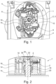
- Figure 1 is a peristaltic blood pump with a rotation unit according to the embodiment of the present disclosure.
- the rotation unit has a rotor 1 and a pin-like drive shaft 2, from which (in Figure 1 ) only head 3 can be seen.
- the rotor 1 has two rollers 4 distributed around its circumference, which are tensioned outwards by the force of a respective pressure spring 6 in the direction of a track-like running surface 8 which is circular in shape at least in a central region.
- a hose segment of a hose (not shown) is placed on the running surface 8.
- the blood to be conveyed is conveyed through the hose segment lying on the running surface 8 by the rollers 4 pressing in the hose segment and the pressed-in point being moved along the hose segment in accordance with the rotation of the rotor 1.
- Figure 2 is a sectional view of the rotation unit from Figure 1
- the rotor 1 is connected in a rotationally fixed manner to a circular cylindrical contact area 20 of the drive shaft 2 in a conveying direction via a frictional coupling 18, while there is a freewheel in the opposite direction.
- the locking element 10 is manufactured in one piece as a stamped and bent sheet metal part and has a contact section 22 which extends into a circumferential groove 24 of the drive shaft 2, which is rotationally symmetrical to the central axis 25, in order to prevent axial removal of the rotor 1 (in Figure 2 upwards).
- the locking element 10 has the actuating section 12 created by bending, which is designed as an actuating surface and can also be viewed as a push button.
- the actuating section 12 is set back radially from the housing section 14. This prevents accidental actuation and thus release of the rotor 1.
- the actuating section 12 is aligned approximately parallel to the central axis 25. This means that the finger used to release the rotor 1 can also be used to remove the rotor 1 with one hand.
- the through-hole 16 in the housing section 14 also serves to ensure that the finger is held securely on the rotor 1.
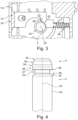
- Figure 3 is a section of the rotation unit from Figure 1 in a cross section through the drive shaft 2.
- a main portion of the locking element 10 is shown in a view (from below), and the actuating portion 12 is shown in section in its angled transition to the main portion of the locking element 10.
- the locking element 10 surrounds the drive shaft 2 on one side, in other words, the locking element 10 has a partially concave recess in which the drive shaft 2 is arranged. At the edge of this recess, a circular arc-shaped contact section 22 is formed, which is tensioned in the direction of the groove 24 of the drive shaft 2 by means of a spring 28.
- the spring 28 is arranged on a side opposite the actuating section 12 with respect to the drive shaft 2 and is designed as a compression spring.
- the spring 28 causes a breakaway force on the Actuating element 12 of at least 10 N, and a removal force for the rotor 1 is at least 12 N. This provides a high level of security against unintentional unlocking and release of the rotor 1.
- a smaller variant of the contact section 22 is shown in solid line. This variant or this contact section 22 extends approximately 82° around the groove 24 or the drive shaft 2.
- the distance required to move out the contact section 22 can be increased if an optional enlargement 26 is provided on the contact section 22 (shown in dotted lines). This variant extends approximately 90° around the groove 24 or the drive shaft 2.
- Figure 4 is a view of the part of the drive shaft 2 from the previous figures onto which the rotor 1 is plugged.
- This part of the drive shaft 2 extends along its central axis 25 and has the head 3 at a free end section, which is delimited by the groove 24 - adjacent when viewed along the central axis 25.
- a conical or frustoconical sliding section 30 formed by a chamfer is arranged on the head 3. This means that the assembly force for the rotor 1 is low.
- This also creates an insertion aid for the shaft holder of the rotor 1, which tolerates an axial offset and a non-vertical plug-on movement and prevents the rotor 1 from getting caught.
- the sliding section 30 extends - viewed along the central axis 25 of the drive shaft - over approximately 35% of the axial extension (the length) of the head 3 and has an angle of 15° to the central axis 25 of the drive shaft 3.
- the head 3 On the side of the chamfer facing away from the groove 24, the head 3 has an end face, with a transition from the chamfer or the sliding section 30 to the end face being rounded with a radius 32 of approximately 1.5 mm. This further simplifies the attachment of the rotor 1 and prevents it from getting caught.
- a circular cylindrical head section 36 is provided which - viewed along the central axis 25 of the drive shaft 2 - extends over approximately 20% of the axial extent (the length) of the head 3.
- a transition from the sliding section 30 to the circular cylindrical head section 36 is rounded with a radius 34 of 4 mm. This further simplifies the attachment of the rotor 1 and prevents it from getting caught.
- a transition from the circular cylindrical head section 36 to the head-side groove flank 37 of the groove 24 is rounded with a radius 38 of 0.25 mm.
- This rounding 38 mainly serves to make it easier to remove the rotor 1 so that it does not get caught so easily during removal.
- the rounding or radius 38 is comparatively small so that it does not have a major influence on the undercut of the locking element 10.
- the circular cylindrical contact area 20 of the frictional coupling 18 is formed on a side of the groove 24 facing away from the head 3.
- a drive-side groove flank 40 arranged between a groove base of the groove 24 and the circular cylindrical contact area 20 is conical or truncated cone-shaped and inclined to the central axis 25.
- a transition 42 from the groove flank 40 to the circular cylindrical contact area 20 is rounded with a radius 42 of 2 mm. This ensures that the fits in the rotor 1, which serve as a bearing point, can be easily guided over the transition 42 and the rotor 1 does not get caught when being plugged on.
- the above embodiments show a peristaltic pump whose drive shaft 2 is rotationally symmetrical, so that a rotor 1 to be plugged on can be plugged on without pressure on the actuating section 12 and without maintaining a predetermined rotational position. Deviations from the ideal plug-on direction are also tolerated due to the conical or truncated cone-shaped sliding section 30 on the head 3 of the drive shaft 2, which is formed by a chamfer.
Landscapes
- Health & Medical Sciences (AREA)
- Engineering & Computer Science (AREA)
- Heart & Thoracic Surgery (AREA)
- Veterinary Medicine (AREA)
- Public Health (AREA)
- Anesthesiology (AREA)
- Biomedical Technology (AREA)
- Hematology (AREA)
- Life Sciences & Earth Sciences (AREA)
- Animal Behavior & Ethology (AREA)
- General Health & Medical Sciences (AREA)
- Cardiology (AREA)
- Mechanical Engineering (AREA)
- Vascular Medicine (AREA)
- General Engineering & Computer Science (AREA)
- Urology & Nephrology (AREA)
- Emergency Medicine (AREA)
- Pulmonology (AREA)
- External Artificial Organs (AREA)
- Reciprocating Pumps (AREA)
Abstract
Description
- Die Offenbarung betrifft eine peristaltische Blutpumpe für ein medizinisches Gerät zur extrakorporalen Blutbehandlung. Derartige Blutpumpen haben ein Pumpengehäuse mit einer gebogenen bahnartigen Lauffläche und einen innerhalb der Lauffläche drehbaren Rotor, wobei ein Schlauchsegment zwischen die Lauffläche und dem Rotor eingelegt ist. Der Rotor ist mit einer Wellenaufnahme auf einer Antriebswelle der Blutpumpe anbringbar, und es ist ein Verriegelungselement zur axialen Sicherung vorgesehen. Derartige peristaltische Pumpen werden auch als Schlauchrollenpumpen bezeichnet.
- Die vorliegende Offenbarung betrifft konkret die Antriebswelle und die Aufsteck- und Sicherungsvorrichtung des Rotors einer derartigen peristaltischen Blutpumpe.
- In medizinischen Geräten zur extrakorporalen Blutbehandlung (Dialyse) werden oftmals peristaltische Schlauchrollenpumpen eingesetzt, welche das entnommene Blut des Patienten zu einem Dialysator und zum Patienten zurückfördern. Dabei liegt ein kreisförmig gekrümmtes Schlauchsegment mit seiner Außenseite an einer entsprechend gekrümmten inneren Lauffläche des Pumpengehäuses an. Ein innerhalb des Schlauchsegments liegender Rotor der Blutpumpe bewegt sich dann mit daran angebrachten Rollen entlang dem Schlauchsegment, wobei die Rollen den Schlauch lokal radial nach außen eindrücken und so mit den elastischen Materialeigenschaften des Schlauchs eine Blutförderung durch den Schlauch erzeugen. Dafür wird das Blut dem Schlauch über einen ersten Anschluss zugeführt und über einen weiteren Anschluss am anderen Ende des Schlauchs wieder abgeführt. Der Schlauch bildet so beispielsweise zusammen mit den zu- und abführenden Leitungen und mehreren Luftfängern ein sogenanntes Überleitsystem, mit dem Blut des Patienten zu einem Dialysator und zum Patienten zurückgefördert wird.
- Aus der
EP 2 682 604 A1 ist eine peristaltische Blutpumpe bekannt. Die Übertragung des Drehmoments von der Antriebswelle zum Rotor erfolgt durch einen Formschluss. Weiterhin ist der Rotor von der Antriebswelle abziehbar, damit der Schlauch gewechselt werden kann. Dazu ist der Rotor auf der Antriebswelle mit einem ebenfalls formschlüssigen Schnappmechanismus bzw. Rastmechanismus axial gesichert. Ein axial wirkendes Verriegelungselement ist mittels eines manuellen und gefederten Druckschalters bewegbar, wodurch der Rotor freigegeben wird und axial abgezogen werden kann. Der Schalter ist so positioniert, dass er beim Ergreifen des Rotors durch das Bedienpersonal der Blutpumpe bzw. des Dialysegerätes gleichzeitig niedergedrückt werden kann. - Das Aufsetzen des Rotors auf die nicht rotationssymmetrische Antriebswelle ist für das Bedienpersonal in den weitaus meisten Fällen mit einem gefühlvollen Folgen einer Drehbewegung des Rotors verbunden, die von der Antriebswelle erzwungen wird. Diese erzwungene Drehbewegung des Rotors stellt für das oftmals unter Zeitdruck stehende Klinikpersonal jedes Mal eine kleine Herausforderung an Geschicklichkeit und/oder Geduld dar.
- Dieser Nachteil ist behoben bei einer unter dem Namen Dialog+ der Anmelderin bekannten peristaltische Blutpumpe, die eine rotationssymmetrische Antriebswelle hat, wodurch die erzwungene Drehbewegung beim Aufstecken des Rotors entfällt. Die Übertagung des Drehmoments von der Antriebswelle auf den Rotor erfolgt in Betrieb der Blutpumpe über einen umfänglichen Reibschluss am kreiszylindrischen Anlagebereich des Außenmantels der Antriebswelle, womit auch ein Freilauf gebildet ist. Um den Rotor von der Antriebswelle zu lösen, muss ein Schalter gedrückt werden, der an der Oberfläche des Rotors angeordnet ist, und dessen Betätigungsfläche bündig mit der dortigen Gehäusewand des Rotors abschließt. Die Betätigungsfläche des Schalters und die dortige Gehäusewand sind senkrecht zur Antriebswelle angeordnet. Daher kann beim Greifen des Rotors durch das Bedienpersonal nicht gleichzeitig mit demselben Finger der Schalter betätigt werden, mit dem auch der Rotor gegriffen und abgezogen wird.
- Bei der unter dem Namen Dialog+ der Anmelderin bekannten peristaltische Blutpumpe sind Rotor und das Schlauchsegment in einem schüsselartig ausgeformten Bereich der Blutpumpe angeordnet, in dessen Mitte zapfenartig die rotationsymmetrische Antriebswelle aus dem Boden herausragt. Die Antriebswelle hat einen Kopf und eine umlaufende Nut, die von einer bodenseitigen geneigten Flanke und von einer kopfseitigen Flanke mit maximaler Steilheit begrenzt ist. In anderen Worten hat die kopfseitige Flanke der Nut die Form eines Kreisrings, der senkrecht zur Mittelachse der Antriebswelle ausgerichtet ist. An dieser kopfseitigen Flanke stützt sich ein Verriegelungselement ab, wenn der Rotor mit einer Kraft weg vom Boden in Abzugsrichtung des Rotors beaufschlagt wird, und wenn nicht gleichzeitig auf die Betätigungsfläche des Schalters gedrückt wird.
- Am Kopf im Übergang zwischen einem kreiszylindrischen Mantel und einer kreisscheibenförmigen Stirnfläche ist eine Verrundung vorgesehen, die zum leichteren Aufstecken des Rotors dient.
- Aufgabe der vorliegenden Offenbarung ist es, eine Antriebswelle für eine peristaltische Blutpumpe und eine Rotationseinheit bestehend aus einer Antriebswelle und einem Rotor für eine peristaltische Blutpumpe zu schaffen, bei denen ein Aufstecken des Rotors weiter vereinfacht ist.
- Diese Aufgabe wird in Hinblick auf die Antriebswelle mit der Merkmalskombination des Anspruchs 1 und im Hinblick auf die Rotationseinheit mit der Merkmalskombination des Anspruchs 10 gelöst.
- Die Antriebswelle gemäß der Offenbarung ist zur Aufnahme durch Aufstecken eines Rotors einer peristaltischen Blutpumpe eingerichtet und ausgelegt. Die Antriebswelle erstreckt sich entlang ihrer Mittelachse und weist an einem freien Endabschnitt einen rotationssymmetrischen Kopf auf, der von einer - entlang der Mittelachse betrachtet benachbarten - Nut begrenzt ist. An dem Kopf ist ein durch eine Fase gebildeter konischer oder kegelstumpfförmiger Gleitabschnitt angeordnet. Damit ist die Montagekraft des Rotors gering. Damit ist auch eine Einführhilfe für den Rotor geschaffen, die einen axialen Versatz und eine nicht senkrechte Aufsteckbewegung toleriert und ein Verhaken des Rotors vermeidet.
- Vorzugsweise erstreckt sich der Gleitabschnitt entlang der Mittelachse der Antriebswelle betrachtet über 30 bis 40%, vorzugsweise 35% der Axialerstreckung (der Länge) des Kopfes.
- Vorzugsweise hat der Gleitabschnitt einen Winkel in einem Bereich von 5° bis 20°, bei einem konkreten Ausführungsbeispiel 15° zur Mittelachse der Antriebswelle.
- An der von der von der Nut abgewandten Seite der Fase bzw. des Gleitabschnitts kann die komplette Stirnseite der Antriebswelle ballig gestaltet sein. Alternativ kann der Kopf der Antriebswelle eine Stirnfläche aufweisen, wobei ein Übergang von der Fase bzw. dem Gleitabschnitt zu der Stirnfläche verrundet ist mit einem Radius vorzugsweise von größer als 1 mm, bei einem konkreten Ausführungsbeispiel 1,5 mm. In beiden Fällen ist das Aufstecken des Rotors weiter vereinfacht und ein Verhaken vermieden.
- Zwischen der Fase bzw. dem Gleitabschnitt und der Nut ist vorzugsweise ein (per se aus dem Stand der Technik bekannter) kreiszylindrischer Kopfabschnitt vorgesehen, der sich - entlang der Mittelachse der Antriebswelle betrachtet - vorzugsweise über 15 bis 25%, bei einem konkreten Ausführungsbeispiel 20% der Axialerstreckung (der Länge) des Kopfes erstreckt.
- Ein Übergang von dem Gleitabschnitt zu dem kreiszylindrischen Kopfabschnitt ist vorzugsweise verrundet mit einem Radius vorzugsweise zwischen 2 bis 6 mm, bei einem konkreten Ausführungsbeispiel 4 mm. Damit ist das Aufstecken des Rotors weiter vereinfacht und ein Verhaken vermieden.
- Mit den vorbeschriebenen Ausgestaltungen der Antriebswelle kann ein tastenloses Aufstecken des Rotors auf relativ kleinem Bauraum realisiert werden.
- Vorzugsweise ist ein Übergang von dem kreiszylindrischen Kopfabschnitt zu der Nut verrundet mit einem Radius vorzugsweise zwischen 0,1 bis 0,3 mm, bei einem konkreten Ausführungsbeispiel 0,25 mm. Diese Verrundung dient hauptsächlich einem einfacheren Entnehmen des Rotors, damit dieser während der Entnahme nicht so leicht verhakt. Die Verrundung ist vergleichsweise klein, damit kein großer Einfluss auf den Hinterschnitt des Verriegelungselements entsteht.
- Bei einer bevorzugten Weiterbildung der Antriebswelle ist an einer von dem Kopf abgewandten Seite der Nut ein kreiszylindrischer Anlagebereich einer oder für eine reibschlüssige Kupplung gebildet. Eine zwischen einem Nutgrund der Nut und dem kreiszylindrischen Anlagebereich angeordnete antriebsseitige Nutflanke ist konisch oder kegelstumpfförmig zur Mittelachse schräg gestellt. Ein Übergang von der Nutflanke zu dem kreiszylindrischen Anlagebereich ist verrundet mit einem Radius vorzugsweise zwischen 1,5 bis 4 mm, bei einem konkreten Ausführungsbeispiel 2 mm. Damit wird erreicht, dass die Passungen im Rotor, die als Lagerstelle dienen, leicht über diese Stelle hinweg geführt werden können und der Rotor beim Aufstecken nicht verhakt.
- Besonders bevorzugt wird es, wenn der Kopf, die Nut und der Anlagebereich für den reibschlüssigen Antrieb rotationssymmetrisch sind. Damit wird erreicht, dass der Rotor in jeder beliebigen Position auf die Welle gesteckt werden kann und die korrekte Drehposition nicht erst gefunden werden muss.
- Die Rotationseinheit gemäß der Offenbarung ist für eine peristaltische Blutpumpe ausgelegt und weist eine vorbeschriebene Antriebswelle und einen darauf ausgesteckten oder aufsteckbaren Rotor mit Schlauchrollen auf. Die Nut hat eine dem Kopf zugewandte und daher als kopfseitig bezeichnete Nutflanke, die senkrecht zur Mittelachse angeordnet ist und damit vorzugsweise die Form eines Kreisrings mit maximaler Steilheit hat. In dem Rotor ist ein Verriegelungselement angeordnet, das quer zur Mittelachse der Antriebswelle bewegbar ist. Ein Anlageabschnitt des Verriegelungselements ist mittels einer Feder radial in Richtung zur Mittelachse und in Richtung zum Nutgrund vorgespannt, wobei der Anlageabschnitt mittels eines am Verriegelungselement befestigten oder einstückig gebildeten Betätigungsabschnitts in Richtung radial weg von der Mittelachse und in Richtung weg vom Nutgrund bewegbar ist. Zumindest eine Anlagefläche des Anlageabschnitts oder der gesamte Anlageabschnitt ist so wie die kopfseitige Nutflanke senkrecht zur Mittelachse angeordnet. Wenn der Rotor mit einer Kraft weg vom Boden des Gehäuses in Abzugsrichtung des Rotors beaufschlagt wird, und wenn dabei nicht auf den Betätigungsabschnitt gedrückt wird, ergibt sich ein sicherer Halt des Rotors im Betrieb der Blutpumpe wegen der senkrechten Ausrichtung einerseits der kopfseitigen Nutflanke und andererseits der Anlagefläche des Anlageabschnitts.
- Der Betätigungsabschnitt kann z.B. eine Betätigungsfläche sein, er kann aber auch eine abweichende z.B. ballige Form haben.
- Vorzugsweise ist der Anlageabschnitt auf einer dem Betätigungsabschnitt gegenüberliegenden Seite der Antriebswelle angeordnet. Dann erzeugt ein Drücken des Betätigungsabschnitts hin zur Antriebswelle ein Herausfahren des Anlageabschnitts auf der anderen Seite der Antriebswelle. Dazu ist ein Überbrückungsabschnitt am Verriegelungselement nötig, der sich vorzugsweise einseitig an der Antriebswelle entlang erstreckt und den Betätigungsabschnitt vorzugsweise einstückig mit dem Anlageabschnitt verbindet.
- Wenn die Feder eine Druckfeder ist, ist diese auch auf der dem Betätigungsabschnitt gegenüberliegenden Seite der Antriebswelle angeordnet.
- Bei einer besonders bevorzugten Ausgestaltung des Verriegelungselements ist der Anlageabschnitt kreisbogenförmig und erstreckt sich in einem Umfangsbereich der Nut. Vorzugsweise erstreckt sich der Anlageabschnitt über 80° bis 96° entlang dem Umfang der Nut. Mit zunehmender Erstreckung in Richtung zum Betätigungsabschnitt verlängert sich der Weg des gesamten Verriegelungselements, der nötig ist, um dessen Anlageabschnitt komplett aus der Nut herauszubewegen. Damit ist die Sicherheit gegen ungewolltes Entriegeln des Rotors erhöht.
- Bei einer vorrichtungstechnisch einfachen Ausgestaltung ist das Verriegelungselement mit dem Betätigungsabschnitt, dem Überbrückungsabschnitt und dem Anlageabschnitt ein gestanztes Blechteil. Dabei kann der Betätigungsabschnitt durch Abwinkeln bzw. Abkanten z.B. um 90° gebildet sein.
- Bei einer bevorzugten Ausgestaltung hat der Betätigungsabschnitt einen geringeren Abstand zur Antriebswelle, als ein den Betätigungsabschnitt umgebender Gehäuseabschnitt des Rotors. Damit ist der Betätigungsabschnitt im Gehäuseabschnitt des Rotors versenkt, und die Sicherheit gegen ungewolltes Drücken und somit Entriegeln des Rotors ist erhöht.
- Bei einer bevorzugten Ausgestaltung bewirkt die Feder eine Losbrechkraft, also eine Betätigungskraft am Betätigungselement ausgehend von einer Verriegelungsposition - von mindestens 10 N. Damit ist die Sicherheit gegen ungewolltes Entriegeln des Rotors gegenüber dem Stand der Technik erhöht. Mit zunehmender Losbrechkraft erhöht sich die Fingerkraft, die nötig ist, um den Anlageabschnitt komplett aus der Nut herauszubewegen. Damit kann die Sicherheit gegen ungewolltes Entriegeln des Rotors weiter erhöht werden.
- Eine Entnahmekraft für den Rotor 1 beträgt mindestens 12 N.
-
-
Figur 1 ist eine peristaltische Blutpumpe mit einer Rotationseinheit gemäß dem Ausführungsbeispiel der vorliegenden Offenbarung; -
Figur 2 ist eine geschnittene Darstellung der Rotationseinheit ausFigur 1 ; -
Figur 3 ist ein Ausschnitt der Rotationseinheit ausFigur 1 in einer weiteren geschnittenen Darstellung mit zwei Varianten eines Anlageabschnitts; -
Figur 4 ist eine Ansicht des für die Offenbarung wesentlichen Teils der Antriebswelle aus den vorhergehenden Figuren. - Nachstehend wird ein Ausführungsbeispiel der Rotationseinheit mit einem Ausführungsbeispiel der Antriebswelle auf der Basis der zugehörigen Figuren beschrieben.
-
Figur 1 ist eine peristaltische Blutpumpe mit einer Rotationseinheit gemäß dem Ausführungsbeispiel der vorliegenden Offenbarung. Die Rotationseinheit weist einen Rotor 1 und eine zapfenartige Antriebswelle 2 auf, von der (inFigur 1 ) nur der Kopf 3 zu erkennen ist. - Der Rotor 1 hat an seinem Umfang verteilt zwei Rollen 4, die über die Kraft eine jeweiligen Andruckfeder 6 nach außen in Richtung zu einer zumindest in einem Mittelbereich kreisbogenförmigen bahnartigen Lauffläche 8 gespannt sind. An der Lauffläche 8 wir ein Schlauchsegment eines (nicht gezeigten) Schlauches angelegt. Das zu fördernde Blut wird durch das an der Lauffläche 8 anliegende Schlauchsegment gefördert, in dem die Rollen 4 das Schlauchsegment eindrücken und die eingedrückte Stelle gemäß der Rotation des Rotors 1 an dem Schlauchsegment entlang bewegt wird.
- Da in
Figur 1 ein Gehäusedeckel des Rotors 1 entfernt ist, ist der Kopf 3 der Antriebswelle 2 zu erkennen. Der Rotor 1 wird in axialer Richtung an der Antriebswelle 2 mit einem als Verriegelungsblech ausgeführten Verriegelungselement 10 gehalten. Dies hat einen als Betätigungsfläche ausgebildeten Betätigungsabschnitt 12, der radial innerhalb eines Gehäuseabschnitts 14 des Rotors 1 angeordnet ist. Durch eine Durchgangsausnehmung 16 des Gehäuseabschnitts 14 kann der Betätigungsabschnitt 12 vom Bedienpersonal gedrückt werden, um die axiale Verriegelung zu lösen und den Rotor 1 von der Antriebwelle 2 abzuziehen. -
Figur 2 ist eine geschnittene Darstellung der Rotationseinheit ausFigur 1 . Der Rotor 1 ist über eine reibschlüssige Kupplung 18 mit einem kreiszylindrischen Anlagebereich 20 der Antriebswelle 2 in einer Förderrichtung drehfest verbunden, während in Gegenrichtung ein Freilauf besteht. - Das Verriegelungselement 10 ist einstückig als Stanz-Biege-Blechteil hergestellt und hat einen Anlageabschnitt 22, der in eine umlaufende Nut 24 der zur Mittelachse 25 rotationsymmetrischen Antriebswelle 2 eintaucht, um ein axiales Abziehen des Rotors 1 (in
Figur 2 nach oben) zu verhindern. - Das Verriegelungselement 10 hat den durch Biegen erzeugten Betätigungsabschnitt 12, der als Betätigungsfläche ausgebildet ist, und der auch als Druckknopf angesehen werden kann. Der Betätigungsabschnitt 12 ist gegenüber dem Gehäuseabschnitt 14 radial zurückgesetzt. Damit ist eine versehentliche Betätigung und somit Lösen des Rotors 1 vermeiden. Der Betätigungsabschnitt 12 ist etwa parallel zur Mittelachse 25 ausgerichtet. Damit kann der Finger, mit dem der Rotor 1 gelöst wird, auch zum einhändigen Herausnehmen des Rotors 1 genutzt werden. Für einen sicheren Halt des Fingers am Rotor 1 dient auch die Durchgangsausnehmung 16 im Gehäuseabschnitt 14.
-
Figur 3 ist ein Ausschnitt der Rotationseinheit ausFigur 1 in einem Querschnitt durch die Antriebswelle 2. Insbesondere ein Hauptabschnitt des Verriegelungselement 10 ist in einer Ansicht (von unten) gezeigt, und der Betätigungsabschnitt 12 ist in seinem abgewinkelten Übergang zum Hauptabschnitt des Verriegelungselements 10 geschnitten dargestellt. - Das Verriegelungselement 10 umgreift die Antriebswelle 2 einseitig, in anderen Worten ausgedrückt hat das Verriegelungselement 10 eine abschnittsweise konkave Ausnehmung, in der die Antriebswelle 2 angeordnet ist. Am Rand dieser Ausnehmung ist ein kreisbogenförmiger Anlageabschnitt 22 gebildet, der in Richtung zur Nut 24 der Antriebswelle 2 mittels einer Feder 28 gespannt ist. die Feder 28 ist auf einer bezüglich der Antriebwelle 2 dem Betätigungsabschnitt 12 gegenüberliegenden Seite angeordnet und als Druckfeder ausgebildet. Die Feder 28 bewirkt eine Losbrechkraft am Betätigungselement 12 von mindestens 10 N, und eine Entnahmekraft für den Rotor 1 beträgt mindestens 12 N. Damit ist eine hohe Sicherheit gegen ungewolltes Entriegeln und Lösen des Rotors 1 gegeben.
- In durchgezogener Linie ist eine kleinere Variante des Anlageabschnitts 22 dargestellt. Diese Variante bzw. dieser Anlageabschnitt 22 erstreckt sich etwa 82° um die Nut 24 bzw. die Antriebswelle 2 herum.
- Der Weg, der zum Herausbewegen des Anlageabschnitts 22 nötig ist, kann vergrößert werden, wenn am Anlageabschnitt 22 eine optionale Vergrößerung 26 vorgesehen wird (gepunktet dargestellt). Diese Variante erstreckt sich etwa 90° um die Nut 24 bzw. die Antriebswelle 2 herum.
-
Figur 4 ist eine Ansicht des Teils der Antriebswelle 2 aus den vorhergehenden Figuren auf den der Rotor 1 ausgesteckt wird. Dieser Teil der Antriebswelle 2 erstreckt sich entlang ihrer Mittelachse 25 und weist an einem freien Endabschnitt den Kopf 3 auf, der von der - entlang der Mittelachse 25 betrachtet benachbarten - Nut 24 begrenzt ist. An dem Kopf 3 ist ein durch eine Fase gebildeter konischer oder kegelstumpfförmiger Gleitabschnitt 30 angeordnet. Damit ist die Montagekraft für den Rotor 1 gering. Damit ist auch eine Einführhilfe für die Wellenaufnahme des Rotors 1 geschaffen, die einen axialen Versatz und eine nicht senkrechte Aufsteckbewegung toleriert und ein Verhaken des Rotors 1 vermeidet. - Der Gleitabschnitt 30 erstreckt sich - entlang der Mittelachse 25 der Antriebswelle betrachtet - über etwa 35% der Axialerstreckung (der Länge) des Kopfes 3 und hat einen Winkel von 15° zur Mittelachse 25 der Antriebswelle 3.
- An der von der von der Nut 24 abgewandten Seite der Fase weist der Kopf 3 eine Stirnfläche auf, wobei ein Übergang von der Fase bzw. dem Gleitabschnitt 30 zu der Stirnfläche verrundet ist mit einem Radius 32 von etwa 1,5 mm. Dadurch ist das Aufstecken des Rotors 1 weiter vereinfacht und ein Verhaken vermieden.
- Zwischen der Fase bzw. dem Gleitabschnitt 30 und der Nut 24 ist ein kreiszylindrischer Kopfabschnitt 36 vorgesehen, der sich - entlang der Mittelachse 25 der Antriebswelle 2 betrachtet - über etwa 20% der Axialerstreckung (der Länge) des Kopfes 3 erstreckt. Ein Übergang von dem Gleitabschnitt 30 zu dem kreiszylindrischen Kopfabschnitt 36 ist verrundet mit einem Radius 34 von 4 mm. Damit ist das Aufstecken des Rotors 1 weiter vereinfacht und ein Verhaken vermieden.
- Ein Übergang von dem kreiszylindrischen Kopfabschnitt 36 zur kopfseitigen Nutflanke 37 der Nut 24 ist verrundet mit einem Radius 38 von 0,25 mm. Diese Verrundung 38 dient hauptsächlich einem einfacheren Entnehmen des Rotors 1, damit dieser während der Entnahme nicht so leicht verhakt. Die Verrundung bzw. der Radius 38 ist vergleichsweise klein, damit kein großer Einfluss auf den Hinterschnitt des Verriegelungselements 10 entsteht.
- An einer von dem Kopf 3 abgewandten Seite der Nut 24 ist der kreiszylindrische Anlagebereich 20 der reibschlüssigen Kupplung 18 gebildet. Eine zwischen einem Nutgrund der Nut 24 und dem kreiszylindrischen Anlagebereich 20 angeordnete antriebsseitige Nutflanke 40 ist konisch oder kegelstumpfförmig zur Mittelachse 25 schräg gestellt. Ein Übergang 42 von der Nutflanke 40 zu dem kreiszylindrischen Anlagebereich 20 ist verrundet mit einem Radius 42 von 2 mm. Damit wird erreicht, dass die Passungen im Rotor 1, die als Lagerstelle dienen, leicht über den Übergang 42 hinweg geführt werden können und der Rotor 1 beim Aufstecken nicht verhakt.
- Zusammenfassend ist in den vorstehenden Ausführungsbeispielen also ein Peristaltikpumpe gezeigt, deren Antriebswelle 2 rotationssymmetrisch ist, so dass ein aufzusteckender Rotor 1 ohne Druck auf den Betätigungsabschnitt 12 und ohne Einhaltung einer vorbestimmte Drehposition aufgesteckt werden kann. Dabei werden wegen des durch eine Fase gebildeten konischen oder kegelstumpfförmigen Gleitabschnitts 30 am Kopf 3 der Antriebwelle 2 auch Abweichungen von der idealen Aufsteckrichtung toleriert.
- Um ein versehentliches Lösen des Rotors 1 von der Antriebswelle 2 zu vermeiden kann ergänzend zumindest eine der folgenden Maßnahmen vorgesehen werden:
- Der Betätigungsabschnitt 12 (Druckknopf) ist gegenüber dem Gehäuseabschnitt 14 des Rotors 1 versenkt.
- Die Feder 28 ist derart ausgelegt, dass der Betätigungsabschnitt 12 eine Losbrechkraft von 10N hat.
- der Anlageabschnitt 22 (mit seiner Anlagefläche für die kopfseitige Nutflanke) erstreckt sich auf einem Kreisbogen um 90° um die Nut 24 herum.
-
- 1
- Rotor
- 2
- Antriebswelle
- 3
- Kopf
- 4
- Rolle
- 6
- Andruckfeder
- 8
- Lauffläche
- 10
- Verriegelungselement
- 12
- Betätigungsabschnitt
- 14
- Gehäuseabschnitt
- 16
- Durchgangsausnehmung
- 18
- Kupplung
- 20
- Anlagebereich (der Antriebswelle)
- 22
- Anlageabschnitt (des Verriegelungselements)
- 24
- Nut
- 25
- Mittelachse
- 26
- (optionale) Vergrößerung des Anlageabschnitts (des Verriegelungselements)
- 28
- Feder
- 30
- Gleitabschnitt
- 32
- Übergang / Radius
- 34
- Übergang / Radius
- 36
- kreiszylindrischer Kopfabschnitt
- 37
- kopfseitige Nutflanke
- 38
- Übergang / Radius
- 40
- antriebsseitige Nutflanke
- 42
- Übergang / Radius
Claims (14)
- Antriebswelle (2) für eine peristaltische Blutpumpe, die zum Aufstecken eines Rotors (1) der Blutpumpe eingerichtet und ausgelegt ist, wobei sich die Antriebswelle (2) entlang einer Mittelachse (25) erstreckt und an einem freien Endabschnitt einen rotationssymmetrischen Kopf (3) hat, der von einer Nut (24) begrenzt ist, wobei die Nut (24) vorzugsweise eine kopfseitige Nutflanke (37) hat, die senkrecht zur Mittelachse (25) angeordnet ist, dadurch gekennzeichnet, dass an dem Kopf (3) ein durch eine Fase gebildeter konischer oder kegelstumpfförmiger Gleitabschnitt (30) angeordnet ist.
- Antriebswelle (2) nach Anspruch 1 dadurch gekennzeichnet, dass sich der Gleitabschnitt (30) entlang der Mittelachse (25) betrachtet über 30 bis 40% der Axialerstreckung des Kopfes (3) erstreckt.
- Antriebswelle (2) nach einem der vorhergehenden Ansprüche dadurch gekennzeichnet, dass der Gleitabschnitt (30) einen Winkel in einem Bereich von 5° bis 20° zur Mittelachse (25) der Antriebswelle (2) hat.
- Antriebswelle (2) nach einem der vorhergehenden Ansprüche, wobei der Kopf (3) eine Stirnfläche hat, dadurch gekennzeichnet, dass ein Übergang (32) von der Stirnfläche zu dem Gleitabschnitt (30) verrundet ist, vorzugsweise mit einem Radius (32) von größer als 1 mm.
- Antriebswelle (2) nach einem der vorhergehenden Ansprüche dadurch gekennzeichnet, dass zwischen dem Gleitabschnitt (30) und der Nut (24) ein kreiszylindrischer Kopfabschnitt (36) vorgesehen ist.
- Antriebswelle (2) nach Anspruch 5 dadurch gekennzeichnet, dass der kreiszylindrische Kopfabschnitt (36) entlang der Mittelachse (25) der Antriebswelle (2) betrachtet in einem Bereich von 15 bis 25% der Axialerstreckung des Kopfes (3) erstreckt.
- Antriebswelle (2) nach Anspruch 5 oder 6 dadurch gekennzeichnet, dass ein Übergang (34) von dem Gleitabschnitt (30) zu dem kreiszylindrischen Kopfabschnitt (36) verrundet ist vorzugsweise mit einem Radius (34) in einem Bereich von 2 bis 6 mm.
- Antriebswelle (2) nach einem der Ansprüche 5 bis 7 dadurch gekennzeichnet, dass ein Übergang (38) von dem kreiszylindrischen Kopfabschnitt (36) zu der Nut (24) verrundet ist vorzugsweise mit einem Radius (38) in einem Bereich von 0,1 bis 0,3 mm.
- Antriebswelle (2) nach einem der vorhergehenden Ansprüche, wobei an einer von dem Kopf (3) abgewandten Seite der Nut (24) ein kreiszylindrischer Anlagebereich (20) gebildet ist, wobei eine zwischen einem Nutgrund und dem kreiszylindrischen Anlagebereich (20) angeordnete antriebsseitige Nutflanke (40) konisch oder kegelstumpfförmig ist, dadurch gekennzeichnet, dass ein Übergang (42) von der antriebsseitigen Nutflanke (40) zu dem kreiszylindrischen Anlagebereich (20) verrundet ist vorzugsweise mit einem Radius (42) in einem Bereich zwischen 1,5 und 4 mm.
- Rotationseinheit für eine peristaltische Blutpumpe mit einer Antriebswelle (2) gemäß einem der vorhergehenden Ansprüche und mit einem darauf ausgesteckten oder aufsteckbaren Rotor (1) mit Schlauchrollen (4), wobei die Nut (24) eine kopfseitige Nutflanke (37) hat, die senkrecht zur Mittelachse (25) angeordnet ist, und wobei in dem Rotor (1) ein Verriegelungselement (10) angeordnet ist, das quer zur Mittelachse (25) bewegbar ist, und dessen Anlageabschnitt (22) mittels einer Feder (28) in Richtung zur Mittelachse (25) und in Richtung zum Nutgrund vorgespannt ist, wobei der Anlageabschnitt (22) mittels eines am Verriegelungselement (10) befestigten oder einstückig gebildeten Betätigungsabschnitts (12) in Richtung weg von der Mittelachse (25) und in Richtung weg vom Nutgrund bewegbar ist, dadurch gekennzeichnet, dass eine Anlagefläche des Anlageabschnitts (22) senkrecht zur Mittelachse (25) angeordnet ist.
- Rotationseinheit nach Anspruch 10 dadurch gekennzeichnet, dass der Anlageabschnitt (22) auf einer dem Betätigungsabschnitt (12) gegenüberliegenden Seite der Antriebswelle (2) angeordnet ist.
- Rotationseinheit nach Anspruch 11 dadurch gekennzeichnet, dass der Anlageabschnitt (22) kreisbogenförmig ist und sich in einem Umfangsbereich der Nut (24) vorzugsweise über 75° bis 95° erstreckt.
- Rotationseinheit nach einem der Ansprüche 10 bis 12 dadurch gekennzeichnet, dass der Betätigungsabschnitt (12) einen geringeren Abstand zur Antriebswelle (2) hat, als ein den Betätigungsabschnitt (12) umgebender Gehäuseabschnitt (14) des Rotors (1).
- Rotationseinheit nach einem der Ansprüche 10 bis 13 dadurch gekennzeichnet, dass das Verriegelungselement (10) - ausgehend von einer Verriegelungsposition - eine Losbrechkraft von mindestens 10 N hat.
Applications Claiming Priority (1)
| Application Number | Priority Date | Filing Date | Title |
|---|---|---|---|
| DE102023115059.6A DE102023115059A1 (de) | 2023-06-07 | 2023-06-07 | Aufsteck- und Sicherungsvorrichtung des Rotors einer peristaltischen Blutpumpe |
Publications (2)
| Publication Number | Publication Date |
|---|---|
| EP4474000A1 true EP4474000A1 (de) | 2024-12-11 |
| EP4474000B1 EP4474000B1 (de) | 2025-08-06 |
Family
ID=91375785
Family Applications (1)
| Application Number | Title | Priority Date | Filing Date |
|---|---|---|---|
| EP24179561.6A Active EP4474000B1 (de) | 2023-06-07 | 2024-06-03 | Aufsteck- und sicherungsvorrichtung des rotors einer peristaltischen blutpumpe |
Country Status (4)
| Country | Link |
|---|---|
| US (1) | US12508357B2 (de) |
| EP (1) | EP4474000B1 (de) |
| CN (1) | CN119103088A (de) |
| DE (1) | DE102023115059A1 (de) |
Citations (5)
| Publication number | Priority date | Publication date | Assignee | Title |
|---|---|---|---|---|
| US4861242A (en) * | 1987-08-19 | 1989-08-29 | Cobe Laboratories, Inc. | Self-loading peristaltic pump |
| US5062775A (en) * | 1989-09-29 | 1991-11-05 | Rocky Mountain Research, Inc. | Roller pump in an extra corporeal support system |
| WO2007080499A1 (en) * | 2006-01-11 | 2007-07-19 | Gilson S.A.S. | Peristaltic pump including an elastically displaceable locking plate |
| US7547200B2 (en) * | 2003-03-13 | 2009-06-16 | Chf Solutions Inc. | Self-loading peristaltic pump for extracorporeal blood circuit |
| EP2682604A1 (de) | 2012-07-03 | 2014-01-08 | B. Braun Avitum AG | Schlauchrollenpumpe mit einem auto-orientierbaren und -verriegelbaren Rotor sowie medizinisches Gerät zur extrakorporalen Blutbehandlung mit Schlauchrollenpumpe |
Family Cites Families (7)
| Publication number | Priority date | Publication date | Assignee | Title |
|---|---|---|---|---|
| DE10118720A1 (de) * | 2001-04-12 | 2002-10-17 | Luk Fahrzeug Hydraulik | Pumpe |
| DE50208947D1 (de) * | 2002-02-27 | 2007-01-25 | Siemens Ag | Motor-Pumpen-Aggregat, insbesondere für eine Kraftfahrzeug-Bremsvorrichtung |
| US6890161B2 (en) * | 2003-03-31 | 2005-05-10 | Assistive Technology Products, Inc. | Disposable fluid delivery system |
| ATE377708T1 (de) * | 2005-03-10 | 2007-11-15 | Lifebridge Medizintechnik Ag | Schlauchpumpe |
| US8834399B2 (en) * | 2010-12-07 | 2014-09-16 | Zoll Lifebridge Gmbh | Cardiopulmonary apparatus and methods for preserving organ viability |
| DE102012105614A1 (de) * | 2012-06-27 | 2014-01-02 | B. Braun Avitum Ag | Deckelvorrichtung zur schwenkbaren Halterung eines Deckels an einem medizinischen Gerät zur extrakorporalen Blutbehandlung; medizinisches Gerät zur extrakorporalen Blutbehandlung mit Deckelvorrichtung |
| DE102012105916A1 (de) * | 2012-07-03 | 2014-01-09 | B. Braun Avitum Ag | Schlauchrollenpumpe mit einem verriegelbaren Rotor und medizinisches Gerät zur extrakorporalen Blutbehandlung mit Schlauchrollenpumpe |
-
2023
- 2023-06-07 DE DE102023115059.6A patent/DE102023115059A1/de active Pending
-
2024
- 2024-06-03 EP EP24179561.6A patent/EP4474000B1/de active Active
- 2024-06-04 CN CN202410713918.4A patent/CN119103088A/zh active Pending
- 2024-06-06 US US18/735,925 patent/US12508357B2/en active Active
Patent Citations (5)
| Publication number | Priority date | Publication date | Assignee | Title |
|---|---|---|---|---|
| US4861242A (en) * | 1987-08-19 | 1989-08-29 | Cobe Laboratories, Inc. | Self-loading peristaltic pump |
| US5062775A (en) * | 1989-09-29 | 1991-11-05 | Rocky Mountain Research, Inc. | Roller pump in an extra corporeal support system |
| US7547200B2 (en) * | 2003-03-13 | 2009-06-16 | Chf Solutions Inc. | Self-loading peristaltic pump for extracorporeal blood circuit |
| WO2007080499A1 (en) * | 2006-01-11 | 2007-07-19 | Gilson S.A.S. | Peristaltic pump including an elastically displaceable locking plate |
| EP2682604A1 (de) | 2012-07-03 | 2014-01-08 | B. Braun Avitum AG | Schlauchrollenpumpe mit einem auto-orientierbaren und -verriegelbaren Rotor sowie medizinisches Gerät zur extrakorporalen Blutbehandlung mit Schlauchrollenpumpe |
Also Published As
| Publication number | Publication date |
|---|---|
| EP4474000B1 (de) | 2025-08-06 |
| DE102023115059A1 (de) | 2024-12-12 |
| US20240408298A1 (en) | 2024-12-12 |
| CN119103088A (zh) | 2024-12-10 |
| US12508357B2 (en) | 2025-12-30 |
Similar Documents
| Publication | Publication Date | Title |
|---|---|---|
| DE69710082T2 (de) | Tragbare peristaltische pumpe | |
| DE102007020573B4 (de) | Schlauchrollenpumpe | |
| DE69720744T2 (de) | Ventil zum gebrauch mit einer intravenösen vorrichtung | |
| DE69709665T2 (de) | Peristaltische miniatur-pumpe | |
| EP1618908B1 (de) | Kupplungsvorrichtung zum Anschliessen einer medizinischen Versorgungsleitung an einen Katheter | |
| DE69402428T2 (de) | Peristalpumpenkassette | |
| EP1346681A2 (de) | Absaugventil für ein Endoskop | |
| EP2679752B1 (de) | Medizinisches Gerät zur extrakorporalen Blutbehandlung mit einer Deckelvorrichtung zur schwenkbaren Halterung eines Deckels an dem medizinischen Gerät | |
| CH688224A5 (de) | Implantierbare Vorrichtung fuer die dosierte Abgabe pharmazeutischer Flüssigkeiten im menschlichen oder tierischen Koerper. | |
| EP2682604B1 (de) | Schlauchrollenpumpe mit einem auto-orientierbaren und -verriegelbaren Rotor sowie medizinisches Gerät zur extrakorporalen Blutbehandlung mit Schlauchrollenpumpe | |
| EP0103073B1 (de) | Schlauchpumpe, insbesondere für medizinische Anwendungen | |
| DE10208692A1 (de) | Medizinisches oder dentalmedizinisches Handstück mit einem in einem Wälzlager gelagerten Drehteil | |
| DE3115373A1 (de) | Nadelloses injektionsgeraet | |
| WO2019016279A1 (de) | Volumetrische pumpe | |
| EP3366923A1 (de) | Flüssigkeitspumpe | |
| EP4474000B1 (de) | Aufsteck- und sicherungsvorrichtung des rotors einer peristaltischen blutpumpe | |
| WO2014128007A1 (de) | Kindergesicherte austragvorrichtung | |
| DE102014112249A1 (de) | Schwenklager | |
| EP3281654B1 (de) | Peristaltikpumpe mit rotatorischem spiel | |
| EP2885035B1 (de) | Einweg-ventileinrichtung | |
| EP3743144B1 (de) | Verbindungs-anordnung zum verbinden eines narkosemittel-behälters mit einem narkosemittel-verdampfer | |
| DE102020113267A1 (de) | Medizinische Schlauchpumpe mit Stempelelementen und zugehörige Schlauchanordnung | |
| DE112004000569T5 (de) | Infusionspumpenvorrichtung | |
| EP2784192A1 (de) | Auflösewalze mit Drehverschluss und Sicherungselement | |
| WO2016173801A1 (de) | Pumpenvorrichtung |
Legal Events
| Date | Code | Title | Description |
|---|---|---|---|
| PUAI | Public reference made under article 153(3) epc to a published international application that has entered the european phase |
Free format text: ORIGINAL CODE: 0009012 |
|
| STAA | Information on the status of an ep patent application or granted ep patent |
Free format text: STATUS: REQUEST FOR EXAMINATION WAS MADE |
|
| 17P | Request for examination filed |
Effective date: 20241007 |
|
| AK | Designated contracting states |
Kind code of ref document: A1 Designated state(s): AL AT BE BG CH CY CZ DE DK EE ES FI FR GB GR HR HU IE IS IT LI LT LU LV MC ME MK MT NL NO PL PT RO RS SE SI SK SM TR |
|
| GRAP | Despatch of communication of intention to grant a patent |
Free format text: ORIGINAL CODE: EPIDOSNIGR1 |
|
| STAA | Information on the status of an ep patent application or granted ep patent |
Free format text: STATUS: GRANT OF PATENT IS INTENDED |
|
| RIC1 | Information provided on ipc code assigned before grant |
Ipc: A61M 60/441 20210101ALI20250221BHEP Ipc: A61M 60/38 20210101ALI20250221BHEP Ipc: A61M 60/279 20210101ALI20250221BHEP Ipc: A61M 60/109 20210101AFI20250221BHEP |
|
| INTG | Intention to grant announced |
Effective date: 20250305 |
|
| GRAS | Grant fee paid |
Free format text: ORIGINAL CODE: EPIDOSNIGR3 |
|
| GRAA | (expected) grant |
Free format text: ORIGINAL CODE: 0009210 |
|
| STAA | Information on the status of an ep patent application or granted ep patent |
Free format text: STATUS: THE PATENT HAS BEEN GRANTED |
|
| AK | Designated contracting states |
Kind code of ref document: B1 Designated state(s): AL AT BE BG CH CY CZ DE DK EE ES FI FR GB GR HR HU IE IS IT LI LT LU LV MC ME MK MT NL NO PL PT RO RS SE SI SK SM TR |
|
| REG | Reference to a national code |
Ref country code: GB Ref legal event code: FG4D Free format text: NOT ENGLISH |
|
| REG | Reference to a national code |
Ref country code: CH Ref legal event code: EP |
|
| REG | Reference to a national code |
Ref country code: IE Ref legal event code: FG4D Free format text: LANGUAGE OF EP DOCUMENT: GERMAN |
|
| REG | Reference to a national code |
Ref country code: DE Ref legal event code: R096 Ref document number: 502024000142 Country of ref document: DE |
|
| REG | Reference to a national code |
Ref country code: NL Ref legal event code: MP Effective date: 20250806 |
|
| PG25 | Lapsed in a contracting state [announced via postgrant information from national office to epo] |
Ref country code: IS Free format text: LAPSE BECAUSE OF FAILURE TO SUBMIT A TRANSLATION OF THE DESCRIPTION OR TO PAY THE FEE WITHIN THE PRESCRIBED TIME-LIMIT Effective date: 20251206 |
|
| PG25 | Lapsed in a contracting state [announced via postgrant information from national office to epo] |
Ref country code: NO Free format text: LAPSE BECAUSE OF FAILURE TO SUBMIT A TRANSLATION OF THE DESCRIPTION OR TO PAY THE FEE WITHIN THE PRESCRIBED TIME-LIMIT Effective date: 20251106 |
|
| REG | Reference to a national code |
Ref country code: LT Ref legal event code: MG9D |
|
| PG25 | Lapsed in a contracting state [announced via postgrant information from national office to epo] |
Ref country code: PT Free format text: LAPSE BECAUSE OF FAILURE TO SUBMIT A TRANSLATION OF THE DESCRIPTION OR TO PAY THE FEE WITHIN THE PRESCRIBED TIME-LIMIT Effective date: 20251209 |
|
| PG25 | Lapsed in a contracting state [announced via postgrant information from national office to epo] |
Ref country code: FI Free format text: LAPSE BECAUSE OF FAILURE TO SUBMIT A TRANSLATION OF THE DESCRIPTION OR TO PAY THE FEE WITHIN THE PRESCRIBED TIME-LIMIT Effective date: 20250806 |
|
| PG25 | Lapsed in a contracting state [announced via postgrant information from national office to epo] |
Ref country code: HR Free format text: LAPSE BECAUSE OF FAILURE TO SUBMIT A TRANSLATION OF THE DESCRIPTION OR TO PAY THE FEE WITHIN THE PRESCRIBED TIME-LIMIT Effective date: 20250806 Ref country code: NL Free format text: LAPSE BECAUSE OF FAILURE TO SUBMIT A TRANSLATION OF THE DESCRIPTION OR TO PAY THE FEE WITHIN THE PRESCRIBED TIME-LIMIT Effective date: 20250806 |
|
| PG25 | Lapsed in a contracting state [announced via postgrant information from national office to epo] |
Ref country code: GR Free format text: LAPSE BECAUSE OF FAILURE TO SUBMIT A TRANSLATION OF THE DESCRIPTION OR TO PAY THE FEE WITHIN THE PRESCRIBED TIME-LIMIT Effective date: 20251107 |
|
| PG25 | Lapsed in a contracting state [announced via postgrant information from national office to epo] |
Ref country code: SE Free format text: LAPSE BECAUSE OF FAILURE TO SUBMIT A TRANSLATION OF THE DESCRIPTION OR TO PAY THE FEE WITHIN THE PRESCRIBED TIME-LIMIT Effective date: 20250806 |
|
| PG25 | Lapsed in a contracting state [announced via postgrant information from national office to epo] |
Ref country code: LV Free format text: LAPSE BECAUSE OF FAILURE TO SUBMIT A TRANSLATION OF THE DESCRIPTION OR TO PAY THE FEE WITHIN THE PRESCRIBED TIME-LIMIT Effective date: 20250806 |
|
| PG25 | Lapsed in a contracting state [announced via postgrant information from national office to epo] |
Ref country code: PL Free format text: LAPSE BECAUSE OF FAILURE TO SUBMIT A TRANSLATION OF THE DESCRIPTION OR TO PAY THE FEE WITHIN THE PRESCRIBED TIME-LIMIT Effective date: 20250806 Ref country code: BG Free format text: LAPSE BECAUSE OF FAILURE TO SUBMIT A TRANSLATION OF THE DESCRIPTION OR TO PAY THE FEE WITHIN THE PRESCRIBED TIME-LIMIT Effective date: 20250806 |
|
| PG25 | Lapsed in a contracting state [announced via postgrant information from national office to epo] |
Ref country code: RS Free format text: LAPSE BECAUSE OF FAILURE TO SUBMIT A TRANSLATION OF THE DESCRIPTION OR TO PAY THE FEE WITHIN THE PRESCRIBED TIME-LIMIT Effective date: 20251106 |
|
| PG25 | Lapsed in a contracting state [announced via postgrant information from national office to epo] |
Ref country code: ES Free format text: LAPSE BECAUSE OF FAILURE TO SUBMIT A TRANSLATION OF THE DESCRIPTION OR TO PAY THE FEE WITHIN THE PRESCRIBED TIME-LIMIT Effective date: 20250806 |
|
| PG25 | Lapsed in a contracting state [announced via postgrant information from national office to epo] |
Ref country code: SM Free format text: LAPSE BECAUSE OF FAILURE TO SUBMIT A TRANSLATION OF THE DESCRIPTION OR TO PAY THE FEE WITHIN THE PRESCRIBED TIME-LIMIT Effective date: 20250806 |
|
| PG25 | Lapsed in a contracting state [announced via postgrant information from national office to epo] |
Ref country code: DK Free format text: LAPSE BECAUSE OF FAILURE TO SUBMIT A TRANSLATION OF THE DESCRIPTION OR TO PAY THE FEE WITHIN THE PRESCRIBED TIME-LIMIT Effective date: 20250806 |
|
| PG25 | Lapsed in a contracting state [announced via postgrant information from national office to epo] |
Ref country code: CZ Free format text: LAPSE BECAUSE OF FAILURE TO SUBMIT A TRANSLATION OF THE DESCRIPTION OR TO PAY THE FEE WITHIN THE PRESCRIBED TIME-LIMIT Effective date: 20250806 |
|
| PG25 | Lapsed in a contracting state [announced via postgrant information from national office to epo] |
Ref country code: EE Free format text: LAPSE BECAUSE OF FAILURE TO SUBMIT A TRANSLATION OF THE DESCRIPTION OR TO PAY THE FEE WITHIN THE PRESCRIBED TIME-LIMIT Effective date: 20250806 Ref country code: SK Free format text: LAPSE BECAUSE OF FAILURE TO SUBMIT A TRANSLATION OF THE DESCRIPTION OR TO PAY THE FEE WITHIN THE PRESCRIBED TIME-LIMIT Effective date: 20250806 |