EP4472797B1 - Bolzeninstallation - Google Patents
Bolzeninstallation Download PDFInfo
- Publication number
- EP4472797B1 EP4472797B1 EP23719898.1A EP23719898A EP4472797B1 EP 4472797 B1 EP4472797 B1 EP 4472797B1 EP 23719898 A EP23719898 A EP 23719898A EP 4472797 B1 EP4472797 B1 EP 4472797B1
- Authority
- EP
- European Patent Office
- Prior art keywords
- stud
- tyre
- arrangement
- hole
- holes
- Prior art date
- Legal status (The legal status is an assumption and is not a legal conclusion. Google has not performed a legal analysis and makes no representation as to the accuracy of the status listed.)
- Active
Links
Images


Classifications
-
- B—PERFORMING OPERATIONS; TRANSPORTING
- B23—MACHINE TOOLS; METAL-WORKING NOT OTHERWISE PROVIDED FOR
- B23P—METAL-WORKING NOT OTHERWISE PROVIDED FOR; COMBINED OPERATIONS; UNIVERSAL MACHINE TOOLS
- B23P5/00—Setting gems or the like on metal parts, e.g. diamonds on tools
-
- B—PERFORMING OPERATIONS; TRANSPORTING
- B02—CRUSHING, PULVERISING, OR DISINTEGRATING; PREPARATORY TREATMENT OF GRAIN FOR MILLING
- B02C—CRUSHING, PULVERISING, OR DISINTEGRATING IN GENERAL; MILLING GRAIN
- B02C4/00—Crushing or disintegrating by roller mills
- B02C4/28—Details
- B02C4/30—Shape or construction of rollers
- B02C4/305—Wear resistant rollers
-
- B—PERFORMING OPERATIONS; TRANSPORTING
- B02—CRUSHING, PULVERISING, OR DISINTEGRATING; PREPARATORY TREATMENT OF GRAIN FOR MILLING
- B02C—CRUSHING, PULVERISING, OR DISINTEGRATING IN GENERAL; MILLING GRAIN
- B02C4/00—Crushing or disintegrating by roller mills
- B02C4/02—Crushing or disintegrating by roller mills with two or more rollers
- B02C4/08—Crushing or disintegrating by roller mills with two or more rollers with co-operating corrugated or toothed crushing-rollers
-
- B—PERFORMING OPERATIONS; TRANSPORTING
- B02—CRUSHING, PULVERISING, OR DISINTEGRATING; PREPARATORY TREATMENT OF GRAIN FOR MILLING
- B02C—CRUSHING, PULVERISING, OR DISINTEGRATING IN GENERAL; MILLING GRAIN
- B02C4/00—Crushing or disintegrating by roller mills
- B02C4/10—Crushing or disintegrating by roller mills with a roller co-operating with a stationary member
- B02C4/18—Crushing or disintegrating by roller mills with a roller co-operating with a stationary member in the form of a bar
- B02C4/20—Crushing or disintegrating by roller mills with a roller co-operating with a stationary member in the form of a bar wherein the roller is corrugated or toothed
-
- B—PERFORMING OPERATIONS; TRANSPORTING
- B02—CRUSHING, PULVERISING, OR DISINTEGRATING; PREPARATORY TREATMENT OF GRAIN FOR MILLING
- B02C—CRUSHING, PULVERISING, OR DISINTEGRATING IN GENERAL; MILLING GRAIN
- B02C4/00—Crushing or disintegrating by roller mills
- B02C4/28—Details
-
- B—PERFORMING OPERATIONS; TRANSPORTING
- B02—CRUSHING, PULVERISING, OR DISINTEGRATING; PREPARATORY TREATMENT OF GRAIN FOR MILLING
- B02C—CRUSHING, PULVERISING, OR DISINTEGRATING IN GENERAL; MILLING GRAIN
- B02C4/00—Crushing or disintegrating by roller mills
- B02C4/28—Details
- B02C4/30—Shape or construction of rollers
-
- B—PERFORMING OPERATIONS; TRANSPORTING
- B23—MACHINE TOOLS; METAL-WORKING NOT OTHERWISE PROVIDED FOR
- B23P—METAL-WORKING NOT OTHERWISE PROVIDED FOR; COMBINED OPERATIONS; UNIVERSAL MACHINE TOOLS
- B23P19/00—Machines for simply fitting together or separating metal parts or objects, or metal and non-metal parts, whether or not involving some deformation; Tools or devices therefor so far as not provided for in other classes
- B23P19/04—Machines for simply fitting together or separating metal parts or objects, or metal and non-metal parts, whether or not involving some deformation; Tools or devices therefor so far as not provided for in other classes for assembling or disassembling parts
-
- B—PERFORMING OPERATIONS; TRANSPORTING
- B02—CRUSHING, PULVERISING, OR DISINTEGRATING; PREPARATORY TREATMENT OF GRAIN FOR MILLING
- B02C—CRUSHING, PULVERISING, OR DISINTEGRATING IN GENERAL; MILLING GRAIN
- B02C2210/00—Codes relating to different types of disintegrating devices
- B02C2210/02—Features for generally used wear parts on beaters, knives, rollers, anvils, linings and the like
-
- F—MECHANICAL ENGINEERING; LIGHTING; HEATING; WEAPONS; BLASTING
- F16—ENGINEERING ELEMENTS AND UNITS; GENERAL MEASURES FOR PRODUCING AND MAINTAINING EFFECTIVE FUNCTIONING OF MACHINES OR INSTALLATIONS; THERMAL INSULATION IN GENERAL
- F16B—DEVICES FOR FASTENING OR SECURING CONSTRUCTIONAL ELEMENTS OR MACHINE PARTS TOGETHER, e.g. NAILS, BOLTS, CIRCLIPS, CLAMPS, CLIPS OR WEDGES; JOINTS OR JOINTING
- F16B11/00—Connecting constructional elements or machine parts by sticking or pressing them together, e.g. cold pressure welding
- F16B11/006—Connecting constructional elements or machine parts by sticking or pressing them together, e.g. cold pressure welding by gluing
Definitions
- This invention relates to installing studs on a high pressure grinding roll (HPGR); more particularly, installing studs on a tyre of an HPGR.
- HPGR high pressure grinding roll
- An HPGR comprises a pair of rollers which are counter-rotated, and which grind ore fed in the gap between the rollers.
- the roller surface experiences very large pressures, so it is common for tungsten carbide studs to be provided on the roller surface, protruding radially therefrom.
- the roller surface is provided by a hollow cylindrical steel tyre that has a plurality of spaced apertures (or holes) into which high wear material studs (typically made from tungsten carbide) are partially inserted during manufacture of the roller, such that an outer portion of each stud protrudes radially beyond the outer surface of the tyre.
- high wear material studs typically made from tungsten carbide
- the studs are retained in their respective holes adhesively. However, it is important that an operatively inner or root end of each stud is in direct contact with the material of the tyre forming the inner or blind end of the associated hole. This ensures that a load applied to a stud during operation is transmitted directly from the stud to the tyre and the adhesive serves primarily to retain the stud in the hole. If there is a gap between the root end of the stud and the inner end of the hole then loads applied to the stud are transmitted to the tyre through the adhesive interface between the stud and the tyre. This can result in failure of the adhesive interface and loosening or even falling out of the stud.
- each stud is manually installed in its associated hole.
- the installation procedure involves the installer introducing an adhesive into a hole in the tyre. After the adhesive is introduced, the installer inserts a stud into the hole.
- a drill mounted tool is then used to engage the operatively outer end of the stud and urge the stud into the hole and at the same time to rotate the stud. This ensures that the entire surface of the stud located in the hole is coated with adhesive. In addition, it permits air trapped in the hole to escape together with excess adhesive.
- One way in which the installation of the stud is checked is by striking the stud, after installation, with a plastic hammer.
- the sound which is emitted differs when the stud is fully inserted and when it is not fully inserted.
- Another way in which the insertion of the stud is checked is by checking the extent to which the stud protrudes from the outer surface of the tyre, e.g., using a straight strip.
- the studs should all protrude from the surface of the tyre by approximately the same distance and if this is not the case it may be necessary to remove the stud and check that it is within specification.
- Each roller has a large number of studs, typically of the order of 15,000 (depending on the size of the roller), and accordingly, the installation of the studs is extremely time consuming and is prone to human error.
- the quantity of adhesive which is applied may vary from hole to hole.
- WO 2021/042221 A discloses an automatic device for the extraction and installation of the means of fixing the liners in a mill.
- WO 2014/124491 A1 discloses an apparatus for suspending and guiding at least one tool externally of a grinding mill.
- a stud installation machine as set forth in claim 1.
- the adhesive dispensing arrangement may include a dispensing head which is insertable into a hole in the tyre and to dispense adhesive onto the surface of the tyre defining the hole.
- the adhesive dispensing arrangement may include a control unit, adhesive storage tank, metering valve and rotary spray, and may be based on components available from: Ecolab Engineering GmbH, of Raiffeisen No 7, 83313 Siegsdorf, Germany. These components may include a Multiline 1000 (trade mark) control unit (https://www.ecolab-engineering.de/en/home/).
- the stud insertion arrangement may include a feed arrangement configured to feed a stud from a supply of studs into an insertion position in which the stud is radially spaced from and aligned with a radially extending stud receiving hole in a tyre of the roller into which the stud is to be inserted, and a stud displacement mechanism configured to displace the stud from the insertion position to insert at least an operatively inner end portion of the stud into the associated hole.
- the stud displacement mechanism may include an actuator which is displaceable between a retracted condition in which a stud is receivable in the insertion position and an extended condition, displacement of the actuator from its retracted condition to its extended condition displacing the stud from the insertion position into the hole in the tyre.
- the actuator may be a linear actuator and displacement of the actuator between its extended and retracted conditions may be effected by a pressurised fluid, e.g., hydraulically or pneumatically.
- the machine may include an indexing arrangement configured to align the at least part of the adhesive dispensing arrangement and the at least part of the stud insertion arrangement with holes in the tyre to ensure accurate dispensing of the adhesive and placement of the studs.
- the indexing arrangement may include a sensor which is configured to sense the position of a hole in the tyre and, in necessary adjust the position of the stud displacement mechanism to align it with the hole in the tyre into which a stud is to be displaced.
- the sensor may include a probe which has a tapered leading end which is insertable into a hole in the tyre and a detector arrangement for detecting lateral loading and/or displacement of the probe which would be indicative of a misalignment of the probe and hence the stud displacement mechanism relative to the holes in the tyre.
- the displacement mechanism, adhesive dispensing head and the probe may be laterally spaced, the spacing between which corresponds to the lateral spacing or pitch spacing of the holes in a row of holes in the tyre.
- the displacement mechanism and the adhesive dispensing head will be aligned with other holes in the row of holes. If, however, the probe is not aligned with a hole, as it is inserted, by virtue of its tapered leading end, it will be deflected. The position of the displacement mechanism and the adhesive dispensing head will be adjusted in response to the direction and extent of the deflection of the probe to bring them into alignment with respective holes in the tyre.
- the pitch spacing of the holes on different tyres may vary. Accordingly, the lateral spacing between the displacement mechanism, adhesive dispensing head and the probe may be adjustable to suit the particular hole spacing of a tyre, thereby enabling the machine to be used to install studs in tyres of different sizes and having differing spacing between the holes.
- the machine may include a tool support module on which at least part of the stud insertion arrangement, adhesive dispensing arrangement and indexing arrangement are mounted and a gantry on which the tool support module is mounted and which is configured to permit displacement of the tool support module relative to a tyre supported on the support arrangement.
- the gantry may be configured to permit displacement of the tool support module at least one of longitudinally, parallel with the axis of rotation, vertically, and transversely relative to the axis of rotation.
- the gantry may be configured to permit displacement of the tool support module along mutually perpendicular X, Y and Z axes.
- the gantry may include a carriage which is displaceable along a first horizontal displacement path which is parallel with the axis of rotation.
- the machine may include a base track on which the carriage is displaceably mounted.
- the gantry may include an intermediate support which is mounted on the carriage and is displaceable relative to the carriage in a second horizontal displacement path which is perpendicular to the first horizontal displacement path.
- the gantry may include an upright support which is mounted on and extends upwardly from the intermediate support and on which the tool support module is mounted.
- the position of the tool support module on the upright support may be adjustable along a vertical displacement path. This arrangement permits displacement of the tool support module in three-dimensions, i.e., along X, Y and Z axes relative to a tyre mounted on the support arrangement.
- the support arrangement may include a first pair of rollers and a second pair of rollers which are spaced longitudinally from the first pair of rollers, the rollers being rotatable about axes of rotation which are parallel with the longitudinal axis of rotation, and which are configured to support the shaft on which the tyre is mounted rotatably thereon for rotation about the longitudinal axis.
- the machine may include a drive arrangement for driving at least one of the rollers to rotate the shaft and hence the tyre supported on the rollers.
- the drive arrangement may be configured to drive both rollers in at least one of the first and second pairs of rollers.
- the drive arrangement may include a motor drivingly connected to the or each roller.
- the position of one or more of the rollers may be adjustable to permit the shafts and tyres of the rollers of different sized HPGRs to be supported thereon and to permit adjustment of the rollers to ensure that the longitudinal axis of rotation extends horizontally.
- the method may include the step of applying adhesive in the hole before the step of feeding the stud.
- Each stud may have an operatively inner end which is inserted into the hole in the tyre and an operatively outer end which is intended to protrude from a radially outer surface of the tyre once the stud has been installed.
- the method includes, prior to inserting a stud, detecting if the stud is in the correct orientation such that when positioned in the insertion position the operatively inner end of the stud is facing the hole in the tyre into which the stud is to be inserted. If the stud is in the incorrect orientation, the method may include returning the stud to the supply of studs and feeding another stud from the supply of studs to the insertion position.
- applying adhesive to the hole includes inserting an adhesive dispensing head into the hole and discharging adhesive from the dispensing head onto the surface of the tyre defining the hole.
- the method includes displacing the stud displacement mechanism laterally so that it is in registration with an adjacent hole in a row of holes in the tyre to permit a stud to be inserted into the adjacent hole.
- the method optionally includes rotating the tyre about a longitudinal axis of rotation so as to bring another row of holes into registration with the stud displacement mechanism to permit the insertion of studs into another row of holes.
- the method includes aligning the displacement mechanism with a hole into which a stud is to be inserted prior to displacing the stud into the hole.
- reference numeral 10 refers generally to a stud installation machine for installing studs in a tyre of an HPGR in accordance with an embodiment of the invention.
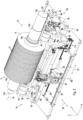
- the HPGR roller 11 with which the machine 10 is intended for use typically comprises an elongate shaft 12 and a hollow, cylindrical tyre 14 mounted on the shaft 12 as an interference fit.
- the shaft 12 extends from a driven end 12a to a mounting end 12h and defines a bearing mounting portion 12c, 12d near each end 12a, 12b and a frusto-conical tyre mounting section 12e located between, and protruding radially from, the bearing mounting portions 12c, 12d of the shaft 12.
- the tyre mounting section 12e may be cylindrical (i.e. having a uniform, circular cross-section).
- a plurality of spaced apart radially extending blind holes 16 open out of a radially outer surface of the tyre 14.
- the holes 16 are typically arranged in circumferentially spaced rows with each row extending generally parallel to a longitudinal axis 18 of the roller 11.
- the machine 10 is used to install studs 70 (best seen in Figures 8 to 10 ) in the holes 16.
- each row is aligned with its adjacent row, however, other configurations may be used.
- adjacent rows may be offset from each other (equally or unequally) such that alternate rows are aligned but adjacent rows are offset. Other configurations are also possible.
- the machine 10 includes a support arrangement, generally indicated by reference numeral 20 for supporting the tyre 14 and shaft 12 for angular displacement about the longitudinal axis 18.
- the machine 10 further includes a stud insertion arrangement, generally indicated by reference numeral 22 (see Figure 7 ), which is configured to insert studs into the holes 16 in the tyre 14 as part of the tyre manufacturing process.
- the stud installation machine 10 further includes an adhesive dispensing arrangement, generally indicated by reference numeral 24 (see Figures 6 and 7 ), and an indexing arrangement, generally indicated by reference numeral 26 (see Figure 7 ).
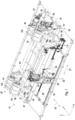
- the machine 10 includes a base, generally indicated by reference numeral 28.
- the base 28 includes a pair of parallel elongate longitudinally extending base members 30 and end members 32 which are connected to the ends of the base members 30.
- the support arrangement 20 includes a first pair of rollers 34, 36 and a second pair of rollers 38, 40.
- Each pair of rollers i.e. the first pair 34, 36 and the second pair 38, 40
- a first roller support structure 42 supports the rollers 34, 36 for rotation about parallel axes of rotation which are parallel with the longitudinal axis 18.
- a second roller support structure 44 supports the rollers 38, 40 at a position which is longitudinally spaced from the first pair of rollers 34, 36 such that the rollers 38, 40 are rotatable about parallel axes which are parallel with the longitudinal axis 18.
- the support structures 42, 44 are configured to permit the lateral spacing between the rollers 34, 36 and 38, 40 to be adjusted in order to support shafts 12 of different diameters.
- the second support structure 44 is longitudinally displaceable along the base members 30 in order to permit the longitudinal spacing between the first roller support structure 42 and second roller support structure 44 to be adjusted,
- the second roller support structure 44 is supported on adjustable shims of jacks 46 to permit the level of the second pair of rollers 38, 40 to be adjusted to ensure that, in use, the longitudinal axis 18 extends horizontally.
- the machine 10 includes a drive arrangement which comprises a pair of motors 48, 50 which are drivingly connected to the rollers 34, 36, respectively, to rotate the rollers 34, 36 and the shaft 12, in use, as described in more detail below.
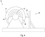
- the machine 10 includes a tool support module, generally indicated by reference numeral 52 (best seen in Figures 5 and 7 ) on which at least part of the stud insertion arrangement 22, adhesive dispensing arrangement 24 and indexing arrangement 26 are mounted.
- a tool support module generally indicated by reference numeral 52 (best seen in Figures 5 and 7 ) on which at least part of the stud insertion arrangement 22, adhesive dispensing arrangement 24 and indexing arrangement 26 are mounted.
- the tool support module 52 is mounted on a gantry 54.
- the gantry 54 includes a carriage 56 which is mounted for displacement in the direction of arrow 57 along a pair of parallel tracks 58 which extend horizontally and parallel with the longitudinal axis 18.
- the gantry 54 further includes an intermediate support 60 which is mounted on the carriage 56 and displaceable in a horizontal plane in the direction of arrow 62, i.e., perpendicular to the direction in which the carriage 56 is displaceable (best seen in Figure 5 ).
- the gantry 54 further includes an upright support 64 which is mounted on the intermediate support 60.
- the tool support module 52 is mounted on the upright support 64 and is vertically displaceable thereon in the direction of arrow 66. Hence, the tool support module 52 is effectively displaceable about mutually perpendicular X, Y and Z axes.
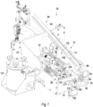
- the stud insertion arrangement 22 includes a stud support 68 which is configured to support a stud 70 in an insertion position in which the stud is radially spaced from and aligned with a radially extending stud receiving hole 16 in the tyre 14.
- the tool support module 52 includes a hollow housing 72 having front face 74.
- the stud support 68 is mounted in the housing 72 in registration with a hole 76 in the front face 74.
- An adjustable stud guide 78 is mounted on the front face 74 and includes a support ring 80, which is in registration with the hole 76, and a plurality of circumferentially spaced radially extending adjustment screws 82 which protrude into a central opening defined by the ring 80. By adjusting the position of the adjustment screws 82 the effective size of the opening can be adjusted to suit the diameter of the studs 70 which are being installed.
- the stud insertion arrangement 22 includes a feed arrangement, generally indicated by reference numeral 84, configured to feed studs 70 from a storage bin 85 to the stud support 68.
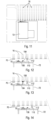
- the feed arrangement 84 includes a first stud lift 86 configured to pick up a stud 70 from the bin 85 and feed it to an intermediate platform 88.
- Tile feed arrangement 84 includes a second stud lift 90 which is configured to displace a stud from the intermediate platform 86 onto an upper end of a slide 92 along which the stud slides downwardly, under the influence of gravity, onto the stud support 68 in which it is in an insertion position ready to be inserted into a hole in the tyre.
- each stud 70 has an operatively inner and 94 which is domed or semi-hemispherical in shape and an operatively outer end 96.
- the feed arrangement 84 includes a sensor 98, typically an optical sensor, which is positioned to sense the orientation of a stud on the intermediate platform 88. If the stud is in the correct orientation, i.e., whereby the operatively inner end 94 will be inserted into a hole in the tyre as described in more detail below, then the stud is displaced by means of the second lift 90 and discharged onto the slide 92. If, however, the sensor 28 determines that the stud is in the incorrect orientation, then the stud is discharged from the intermediate platform 88 back into the bin 85 and a fresh stud 70 is displaced from the bin 85 by means of the lift 86 onto the intermediate platform 88. Only when a stud 70 which is in the correct orientation is sensed is the stud displaced from the intermediate platform 88 via the second lift 90 and onto the slide 92,
- the stud insertion arrangement 22 further includes a stud displacement mechanism, generally indicated by reference numeral 100 which comprises a pneumatically activated ram 102 which is displaceable between a retracted position, in which a stud is receivable on the stud support 68 and an insertion position or extended position in which the ram displaces the stud forwardly from the stud support through the hole 76 and ring 80 into a hole 16 in the tyre 14.
- a stud displacement mechanism generally indicated by reference numeral 100 which comprises a pneumatically activated ram 102 which is displaceable between a retracted position, in which a stud is receivable on the stud support 68 and an insertion position or extended position in which the ram displaces the stud forwardly from the stud support through the hole 76 and ring 80 into a hole 16 in the tyre 14.
- the adhesive dispensing arrangement 24 includes an extendable arm 104 which extends through a hole 105 in the front face 74 of the housing 72.
- a dispensing head 106 is mounted on a free or protruding end of the arm '104.
- Tile arm 104 is connected to a pressurised adhesive supply 107 and is configured to be displaced between a retracted position in which it is clear of the tyre 14 and an extended position in which the dispensing head 106 is inserted into a hole 16 in the tyre where adhesive can be dispensed from the dispensing head 106 onto the surface of the tyre defining the hole 16.
- a collection receptacle 108 is provided to collect any excess adhesive which may drip from the dispensing head 106.
- the indexing arrangement 26 includes a sensor 109 (such as an inductive sensor) configured to sense the position of a hole 16 in the tyre 14 and a control system configured, if necessary, to adjust the position of the tool support module 52 (for example, in the direction of arrows 57 or 66) to align the stud guide 78 and adhesive dispensing arm 104 with holes 16 in the tyre 14 as described in more detail below.
- a sensor 109 such as an inductive sensor
- control system configured, if necessary, to adjust the position of the tool support module 52 (for example, in the direction of arrows 57 or 66) to align the stud guide 78 and adhesive dispensing arm 104 with holes 16 in the tyre 14 as described in more detail below.
- the sensor 109 is coupled to a probe 110 which protrudes through a hole 111 in the front face 74 of the housing 72 and is displaceable between a rest or retracted position and an extended position.
- the probe 110 has a tapered leading end 112 and the sensor 109 includes one or more inductive sensors (such as inductive analogue proximity sensors) for detecting transverse (such as lateral) loads on the probe 110.
- inductive sensors such as inductive analogue proximity sensors
- the machine 10 further includes a stud feed arrangement, generally indicated by reference numeral 114 configured to feed studs from a storage receptacle or hopper 115 into the bin 85.
- a stud feed arrangement generally indicated by reference numeral 114 configured to feed studs from a storage receptacle or hopper 115 into the bin 85.
- the spacing between holes in a row may be different.
- the arm 104 and probe 110 are mounted in the housing such that they are laterally displaceable to permit the relative lateral spacing between the probe 110, arm 112 and stud support 68 to be adjusted to correspond to the pitch spacing between the holes in the particular tyre 14 into which the studs 70 are being inserted.
- the machine 10 when installed, is set up such that the rollers 34, 36, 38, 40 are positioned to support the shaft 12 with the longitudinal axis 18 extending horizontally.
- a laser alignment device generally indicated by reference numeral 120 ( Figure 1 ), may be used.
- the position of the housing 72 is adjusted such that the holes in the front face 74 through which the stud 70, arm 104 and probe 110 protrude are at the same height as the longitudinal axis 18 aligned with a row of holes 16 in the tyre 14.
- the housing 72 is positioned at a desired radial spacing from the radially outer surface of the tyre 14. With a stud 70 positioned on the stud support 68, the probe 110 is extended ( Figure 12 ) into a hole 16 in the tyre 14.
- the probe 110 If the probe 110 is aligned with the hole 16, then it will not touch the sides of the hole 16 and no lateral forces will be applied to the probe 110 enabling it to move freely into and out of the hole 16.
- the spacing between the probe 110, arm 104 and stud guide 78 are selected to correspond to the pitch spacing between holes 16 in a row of holes 16. Accordingly, if the probe 110 is aligned with a hole 16, then so too will the arm 104 and stud guide 78 be aligned with other holes 16 in the row of holes 16.
- the sensor 109 is configured to determine the direction and extent of the displacement of the housing 72 which is required to bring the probe 110 into alignment with the hole 16 and therefore also to bring the arm 104 and stud guide 78 into alignment with adjacent holes 16 in the row.
- the sensor 109 communicates this direction and distance information to a controller (not shown) that moves the tool support module 52 accordingly so that the probe 110 is brought into alignment with the respective hole 16.
- the arm 104 is extended such that the dispensing head 106 is positioned in the hole with which it is aligned where a predetermined volume of adhesive is dispensed in the hole onto the surface of the tyre defining the sides of the hole.
- the ram 102 is extended in order to displace the stud 70 into a hole in which adhesive has already been dispensed thereby inserting the stud 70 into the hole such that the operatively inner end of the stud abuts against the root or inner end of the associated hole.
- the arm 104 is retracted. Further, once the stud has been inserted into the hole, the ram 102 is retracted and a fresh stud 70 is fed by means of the feed arrangement 84 onto the stud support 68. As illustrated in Figure 14 of the drawings, the housing 72 is then displaced laterally such that the probe 110 is aligned with an adjacent hole in the row of holes and the process described above is repeated thereby dispensing adhesive and inserting a stud into each of the holes in the row.
- the motors 48, 50 are activated to rotate the shaft 12 and tyre 14 by an amount sufficient to bring a subsequent (which may be an adjacent) row of holes into registration with the probe 110, arm 102 and stud guide 78 and the process described above is repeated to install studs 70 in each of the holes 16.
- a stud installation machine 10 in accordance with the above embodiment should greatly increase the speed with which studs 70 can be installed in the holes 16 in a tyre 14.
- the machine 10 will permit the studs 70 to be installed with greater consistency (due to the defined amount of force and adhesive used) thereby reducing the risk of an incorrectly installed stud 70.
- sensor 109 may comprise a sensor other than an inductive sensor, for example, it may include a strain gauge.
Landscapes
- Engineering & Computer Science (AREA)
- Food Science & Technology (AREA)
- Mechanical Engineering (AREA)
- Testing Of Balance (AREA)
- Constituent Portions Of Griding Lathes, Driving, Sensing And Control (AREA)
Claims (14)
- Bolzeninstallationsmaschine (10) zum Einbauen von Bolzen (70) in einen Reifen (14) einer Hochdruckschleifwalze (High Pressure Grinding Roller, HPGR), wobei die Maschine (10) umfasst:(i) eine Trägeranordnung (20), dazu eingerichtet, einen Reifen (14) und eine Welle (12) zu tragen, auf der der Reifen (14) für eine Winkelverschiebung um eine Längsdrehachse (18) montiert ist;(ii) eine Bolzeneinsetzanordnung (22), von der mindestens ein Abschnitt in Bezug auf einen auf der Trägeranordnung (20) abgestützten Reifen (14) verschiebbar ist und die dazu eingerichtet ist, Bolzen (70) in Löcher (16) in dem Reifen (14) einzusetzen; und(iii) ferner umfassend eine Klebstoffabgabeanordnung (24), von der mindestens ein Abschnitt in Bezug auf einen Reifen (14), der auf der Trägeranordnung (20) abgestützt ist, verschiebbar ist und die dazu eingerichtet ist, Klebstoff in Löcher (16) in dem Reifen (14) abzugeben, bevor Bolzen (70) in die Löcher (16) eingesetzt werden.
- Bolzeninstallationsmaschine nach Anspruch 1, wobei die Klebstoffabgabeanordnung (24) ferner einen Abgabekopf (106) umfasst, der in ein Loch (16) in dem Reifen (14) einführbar ist.
- Bolzeninstallationsmaschine nach Anspruch 2, wobei die Bolzeneinsetzanordnung (22) ferner eine Zuführanordnung (84) umfasst, die dazu eingerichtet ist, einen Bolzen (70) aus einem Vorrat von Bolzen (85) in eine Einsetzposition zuzuführen, in der der Bolzen (70) radial von einem sich radial erstreckenden Bolzenaufnahmeloch (16) in einem Reifen (14) einer Walze beabstandet und mit diesem ausgerichtet ist, in den der Bolzen (70) einzusetzen ist, und einen Bolzenverschiebungsmechanismus (100), der dazu eingerichtet ist, den Bolzen (70) aus der Einsetzposition zu verschieben und mindestens einen funktionell inneren Endabschnitt (94) des Bolzens (70) in das zugehörige Loch (16) einzusetzen.
- Bolzeninstallationsmaschine nach Anspruch 3, wobei der Bolzenverschiebungsmechanismus (100) ferner einen linearen Aktuator (102) umfasst, der zwischen einem eingefahrenen Zustand, in dem ein Bolzen (70) in der Einführposition aufgenommen werden kann, und einem ausgefahrenen Zustand verschiebbar ist, wobei ein Verschieben des linearen Aktuators (102) aus seinem eingefahrenen Zustand in seinen ausgefahrenen Zustand den Bolzen (70) aus der Einführposition in das Loch (16) in dem Reifen (14) verschiebt.
- Bolzeninstallationsmaschine nach einem der Ansprüche 1 bis 4, ferner umfassend eine Indexierungsanordnung (26), die dazu eingerichtet ist, den mindestens einen Abschnitt der Abgabeanordnung (24) und den mindestens einen Abschnitt der Bolzeneinsetzanordnung (22) mit Löchern (16) in dem Reifen (14) auszurichten, um eine genaue Abgabe des Klebstoffs und die Platzierung der Bolzen (70) zu gewährleisten.
- Bolzeninstallationsmaschine nach Anspruch 5, wobei die Indexierungsanordnung (26) einen Sensor (109) umfasst, der dazu eingerichtet ist, die Position eines Lochs (16) in dem Reifen (14) zu erfassen und, falls erforderlich, die Position des Bolzenverschiebungsmechanismus (100) anzupassen, um ihn auf das Loch (16) auszurichten, in das ein Bolzen (70) zu verschieben ist.
- Bolzeninstallationsmaschine nach Anspruch 6, wobei der Sensor (109) mit einer Sonde (110) gekoppelt ist, die ein sich verjüngendes vorderes Ende (112) aufweist, das in ein Loch (16) in dem Reifen (14) einführbar ist, und eine Detektoranordnung für ein Detektieren einer seitlichen Belastung und/oder Verschiebung der Sonde (110), die auf eine Fehlausrichtung der Sonde (110) und damit des Bolzenverschiebungsmechanismus (100) in Bezug auf die Löcher (16) in dem Reifen (14) hinweisen würde.
- Bolzeninstallationsmaschine nach Anspruch 7, wobei der Verschiebungsmechanismus (100), ein Klebstoffabgabekopf (106) und die Sonde (110) seitlich entlang einer Linie beabstandet sind, der Abstand zwischen ihnen dem seitlichen Abstand oder dem Teilungsabstand der Löcher (16) in einer Reihe von Löchern (16) in dem Reifen (14) entspricht, sodass, wenn die Sonde (110) auf ein Loch (16) in einer Reihe von Löchern (16) ausgerichtet ist, der Verschiebungsmechanismus (100) und der Klebstoffabgabekopf (106) automatisch auf andere Löcher (16) in der Reihe von Löchern (16) ausgerichtet werden.
- Bolzeninstallationsmaschine nach einem der Ansprüche 6 bis 8, ferner umfassend ein Werkzeugträgermodul (52), an dem mindestens ein Abschnitt der Bolzeneinsetzanordnung (100), der Klebstoffabgabeanordnung (24) und der Indexierungsanordnung (26) montiert ist, und ein Portal (54), an dem das Werkzeugträgermodul (52) montiert ist und das dazu eingerichtet ist, eine Verschiebung des Werkzeugträgermoduls (52) in Bezug auf einen auf der Trägeranordnung (20) getragenen Reifen (14) zu ermöglichen.
- Bolzeninstallationsmaschine nach Anspruch 9, wobei das Portal (54) dazu eingerichtet ist, eine Verschiebung des Werkzeugträgermoduls (52) in Längsrichtung, parallel zu der Drehachse (18), vertikal oder quer in Bezug auf die Drehachse (18) zu ermöglichen.
- Bolzeninstallationsmaschine nach Anspruch 10, wobei das Portal (54) dazu eingerichtet ist, eine Verschiebung des Werkzeugträgermoduls (52) entlang der zueinander senkrechten Achsen X, Y und Z zu ermöglichen.
- Bolzeninstallationsmaschine nach einem der Ansprüche 9 bis 11, wobei das Portal (54) einen Schlitten (56) aufweist, der entlang einer ersten horizontalen Verschiebebahn, die parallel zu der Drehachse (18) verläuft, verschiebbar ist.
- Verfahren zum Installieren von Bolzen (70) auf einer Walze einer Hochdruckschleifwalze (HPGR), umfassend die Schritte:(i) Aufbringen von Klebstoff in ein sich radial erstreckendes Bolzenaufnahmeloch (16) in einem Reifen (14) der Walze;(ii) Zuführen eines Bolzens (70) aus einem Vorrat von Bolzen (85) in eine Einsetzposition, in der der Bolzen (70) radial von dem Bolzenaufnahmeloch (16) beabstandet und auf dieses ausgerichtet ist; und(iii)Verschieben des Bolzens (70) mittels eines Bolzenverschiebungsmechanismus (100), um mindestens einen funktionell inneren Endabschnitt (94) des Bolzens (70) in das zugehörige Loch (16) einzusetzen.
- Verfahren nach Anspruch 13, wobei ein Verschieben des Bolzens (70) in das Loch (16) ferner ein Aktivieren eines Aktuators (102) aus einem eingefahrenen Zustand, in dem der Bolzen (70) in der Einführposition aufgenommen werden kann, in einen ausgefahrenen Zustand umfasst, in dem er den Bolzen (70) aus der Einführposition in das Loch (16) verschiebt.
Applications Claiming Priority (2)
| Application Number | Priority Date | Filing Date | Title |
|---|---|---|---|
| GB2205609.7A GB2617619B (en) | 2022-04-14 | 2022-04-14 | Stud installation |
| PCT/IB2023/053353 WO2023199164A1 (en) | 2022-04-14 | 2023-04-03 | Stud installation |
Publications (3)
| Publication Number | Publication Date |
|---|---|
| EP4472797A1 EP4472797A1 (de) | 2024-12-11 |
| EP4472797C0 EP4472797C0 (de) | 2025-02-26 |
| EP4472797B1 true EP4472797B1 (de) | 2025-02-26 |
Family
ID=81753235
Family Applications (1)
| Application Number | Title | Priority Date | Filing Date |
|---|---|---|---|
| EP23719898.1A Active EP4472797B1 (de) | 2022-04-14 | 2023-04-03 | Bolzeninstallation |
Country Status (8)
| Country | Link |
|---|---|
| US (1) | US20250249461A1 (de) |
| EP (1) | EP4472797B1 (de) |
| CN (1) | CN119110759A (de) |
| AU (1) | AU2023253843B2 (de) |
| CL (1) | CL2024002950A1 (de) |
| GB (1) | GB2617619B (de) |
| PE (1) | PE20251349A1 (de) |
| WO (1) | WO2023199164A1 (de) |
Citations (10)
| Publication number | Priority date | Publication date | Assignee | Title |
|---|---|---|---|---|
| US4662556A (en) | 1983-10-21 | 1987-05-05 | Atlas Copco Aktiebolag | Device for assembling by riveting two or more sections of a structure |
| US20110239448A1 (en) | 2007-04-06 | 2011-10-06 | The Boeing Company | Method and apparatus for installing fasteners |
| WO2013181717A1 (en) | 2012-06-08 | 2013-12-12 | Clyde Campbell | A grinding mill installation |
| WO2014124491A1 (en) | 2013-02-14 | 2014-08-21 | Russell Mineral Equipment Pty Ltd | Suspension and guidance apparatus for tool relative to a mill |
| CN104148140A (zh) | 2014-07-22 | 2014-11-19 | 中信重工机械股份有限公司 | 一种高压辊磨机快速更换辊面柱钉的换钉装置及换钉方法 |
| CN107866306A (zh) | 2017-11-14 | 2018-04-03 | 成都利君实业股份有限公司 | 一种柱钉式高压辊磨机辊面及其生产方法 |
| CN207757554U (zh) | 2017-10-25 | 2018-08-24 | 抚顺罕王傲牛矿业股份有限公司 | 高压辊磨机的专用拔钉器 |
| CN111299958A (zh) | 2020-03-30 | 2020-06-19 | 安徽马钢设备检修有限公司 | 一种矿山高压辊磨机辊子上的柱钉镶嵌装置及其焊补工艺 |
| WO2021042221A1 (es) | 2019-09-03 | 2021-03-11 | Mi Robotic Solutions S.A. | Dispositivo o herramienta automática para la extracción e instalación de los medios de fijación de los revestimientos en un molino; procedimiento de instalación de los medios de fijación de un revestimiento; procedimiento de remoción de los medios de fijación de un revestimiento |
| CN112719851A (zh) | 2020-12-30 | 2021-04-30 | 广西钢铁集团有限公司 | 一种高压辊磨机辊钉反冲型拔钉器 |
Family Cites Families (3)
| Publication number | Priority date | Publication date | Assignee | Title |
|---|---|---|---|---|
| CN203108598U (zh) * | 2013-01-10 | 2013-08-07 | 中建材(合肥)粉体科技装备有限公司 | 高压辊磨机的辊结构 |
| WO2014204507A1 (en) * | 2013-06-20 | 2014-12-24 | Flsmidth A/S | Modular protection for grinding rolls |
| CN105413804A (zh) * | 2015-12-03 | 2016-03-23 | 中钢集团安徽天源科技股份有限公司 | 一种高压辊磨机辊面结构及制作方法 |
-
2022
- 2022-04-14 GB GB2205609.7A patent/GB2617619B/en active Active
-
2023
- 2023-04-03 CN CN202380032590.3A patent/CN119110759A/zh active Pending
- 2023-04-03 PE PE2024002208A patent/PE20251349A1/es unknown
- 2023-04-03 EP EP23719898.1A patent/EP4472797B1/de active Active
- 2023-04-03 WO PCT/IB2023/053353 patent/WO2023199164A1/en not_active Ceased
- 2023-04-03 US US18/851,545 patent/US20250249461A1/en active Pending
- 2023-04-03 AU AU2023253843A patent/AU2023253843B2/en active Active
-
2024
- 2024-10-01 CL CL2024002950A patent/CL2024002950A1/es unknown
Patent Citations (10)
| Publication number | Priority date | Publication date | Assignee | Title |
|---|---|---|---|---|
| US4662556A (en) | 1983-10-21 | 1987-05-05 | Atlas Copco Aktiebolag | Device for assembling by riveting two or more sections of a structure |
| US20110239448A1 (en) | 2007-04-06 | 2011-10-06 | The Boeing Company | Method and apparatus for installing fasteners |
| WO2013181717A1 (en) | 2012-06-08 | 2013-12-12 | Clyde Campbell | A grinding mill installation |
| WO2014124491A1 (en) | 2013-02-14 | 2014-08-21 | Russell Mineral Equipment Pty Ltd | Suspension and guidance apparatus for tool relative to a mill |
| CN104148140A (zh) | 2014-07-22 | 2014-11-19 | 中信重工机械股份有限公司 | 一种高压辊磨机快速更换辊面柱钉的换钉装置及换钉方法 |
| CN207757554U (zh) | 2017-10-25 | 2018-08-24 | 抚顺罕王傲牛矿业股份有限公司 | 高压辊磨机的专用拔钉器 |
| CN107866306A (zh) | 2017-11-14 | 2018-04-03 | 成都利君实业股份有限公司 | 一种柱钉式高压辊磨机辊面及其生产方法 |
| WO2021042221A1 (es) | 2019-09-03 | 2021-03-11 | Mi Robotic Solutions S.A. | Dispositivo o herramienta automática para la extracción e instalación de los medios de fijación de los revestimientos en un molino; procedimiento de instalación de los medios de fijación de un revestimiento; procedimiento de remoción de los medios de fijación de un revestimiento |
| CN111299958A (zh) | 2020-03-30 | 2020-06-19 | 安徽马钢设备检修有限公司 | 一种矿山高压辊磨机辊子上的柱钉镶嵌装置及其焊补工艺 |
| CN112719851A (zh) | 2020-12-30 | 2021-04-30 | 广西钢铁集团有限公司 | 一种高压辊磨机辊钉反冲型拔钉器 |
Non-Patent Citations (15)
| Title |
|---|
| D11 - E-MAIL VON HERRN CHRISTIAN HÖVELS (HENKEL AG & CO. KGAA) VOM 10. SEPTEMBER 2015 ZUR BESTÄTIGUNG EINES GESPRÄCHS IM HAUSE KÖPPERN |
| D12 - GESPRÄCHSBERICHT VON HERRN FALK MARTELL (KÖPPERN ENTWICKLUNGS-GMBH, TOCHTERUNTERNEHMEN DER EINSPRECHENDEN) |
| D13 - GESPRÄCHSNOTIZ VON HERRN MARTELL ZU EINEM GESPRÄCH VOM 25. SEPTEMBER 2015 MIT HERRN HÖVELS |
| D14 - E-MAIL VON HERRN TYLINSKI (KÖPPERN ENTWICKLUNGS-GMBH) VOM 7. OKTOBER 2015 AN HERRN DR. AXEL HÖFTER |
| D15 - BESUCHSBERICHT VON HERRN DR. EGGERT DE WELDIGE VOM 8. OKTOBER 2015 ÜBER EINEN BESUCH DER MESSEN BONDEXPO UND MOTEK IN STUTTGART |
| D16 - ANGEBOT DER HENKEL AG & CO. KGAA VOM 11.10.2015 BETREFFEND EINEN ROTORDISPENSER "LOCTITE 97115" MIT STEUERGERÄT "LOCTITE 97152" |
| D17 - BESTELLUNG DER KÖPPERN ENTWICKLUNGS-GMBH VOM 7. DEZEMBER 2015 |
| D17A - BEDIENUNGSANLEITUNG HENKEL, LOCTITE ROTORSPRAY ROTOREINHEIT 97115, AUSGABE 6/2015 |
| D17B - BEDIENUNGSANLEITUNG HENKEL UNIVERSAL-STEUERGERÄT, LOCTITE 97152, 21. NOVEMBER 2018 |
| D17C - LOCTITE HANDBUCH FÜR GERÄTETECHNIK, 5. AUFL., 2015, HENKEL AG & CO. KGAA |
| D18 - ARBEITSANWEISUNG DER KÖPPERN ENTWICKLUNGS-GMBH FÜR DIE PRODUKTION VON BANDAGEN MIT VERSCHLEISSSCHUTZ VOM 30. MAI 2017 |
| D19 - AUFTRAGSBESTÄTIGUNG VOM 3. SEPTEMBER 2019 BETREFFEND EINE BESTELLUNG VOM 3. SEPTEMBER 2019 |
| D20 - RECHNUNG UND VERSANDNACHWEIS BETREFFEND DIE BESTELLUNG GEMÄSS ANLAGE A9 |
| D21 - ARBEITSANWEISUNG DER KÖPPERN ENTWICKLUNGS-GMBH VOM 27. SEPTEMBER 2018 FÜR DIE JSC STOILENSKY MINING & PROCESSING PLANT |
| D22A/B/C/D - SCREENSHOT YOUTUBE-VIDEO DER FIRMA TAKRAF MIT DEM TITEL "CHANGE OF ROLL BODIES OF A ROLLER PRESS HPGR" |
Also Published As
| Publication number | Publication date |
|---|---|
| GB2617619A (en) | 2023-10-18 |
| EP4472797C0 (de) | 2025-02-26 |
| EP4472797A1 (de) | 2024-12-11 |
| US20250249461A1 (en) | 2025-08-07 |
| AU2023253843A1 (en) | 2024-09-26 |
| CL2024002950A1 (es) | 2025-01-10 |
| GB202205609D0 (en) | 2022-06-01 |
| AU2023253843B2 (en) | 2025-08-28 |
| CN119110759A (zh) | 2024-12-10 |
| WO2023199164A1 (en) | 2023-10-19 |
| GB2617619B (en) | 2024-08-07 |
| PE20251349A1 (es) | 2025-05-19 |
Similar Documents
| Publication | Publication Date | Title |
|---|---|---|
| CN101205699B (zh) | 路面碾轧机械和用于测量碾轧深度的方法 | |
| AU720206B2 (en) | Tire uniformity testing system | |
| US6062807A (en) | Battery plate feeder having oscillating pick-up head | |
| CN102164706A (zh) | 定心装置及定心方法 | |
| KR101072880B1 (ko) | 미세 금속파이프의 엔드 포밍장치 | |
| CH642584A5 (it) | Gruppo alimentatore di utensili, per macchine utensili ad asportazione di truciolo. | |
| KR102022959B1 (ko) | 휠과 타이어를 정밀하고 빠르게 조립할 수 있는 휠 타이어 자동 조립라인 | |
| EP4472797B1 (de) | Bolzeninstallation | |
| DE3900491A1 (de) | Messeinrichtung fuer eine rundschleifmaschine | |
| EP0954452B1 (de) | Lastradanordnung für reifenprüfsystem | |
| EP0427714B1 (de) | Automatisches beladegerät für papierrollen und anderes material | |
| KR101141340B1 (ko) | 대형 베어링 매칭기 | |
| CN115533336B (zh) | 一种钻杆切割装置 | |
| CN105945166A (zh) | 一种管道自动上料设备 | |
| EP3479945B1 (de) | Automatischer elektrodenwechsler für funkenerosionsbearbeitung | |
| KR101316334B1 (ko) | 프레스를 이용한 볼 베어링의 볼 조립 장치 | |
| CN111805097B (zh) | 一种激光断料机的自动上料装置 | |
| CN212041528U (zh) | 用于滚针轴承的检测装置 | |
| KR101665198B1 (ko) | 냉간 단조용 냉간 인발 바의 제작 시스템 및 방법 | |
| CN111420891A (zh) | 轮毂圆度自动检测分料装置 | |
| CN209683191U (zh) | 半导体封测用全自动激光打标系统打标装置 | |
| CN116550632B (zh) | 一种滚子分选机及工作方法 | |
| US20240246791A1 (en) | Device that feeds an elongated workpiece to a forming machine, retrofit kit, forming installation, and method of operating a device | |
| KR102697971B1 (ko) | 공작기계의 환봉 정렬 및 공급장치 | |
| JPH0453876Y2 (de) |
Legal Events
| Date | Code | Title | Description |
|---|---|---|---|
| STAA | Information on the status of an ep patent application or granted ep patent |
Free format text: STATUS: UNKNOWN |
|
| STAA | Information on the status of an ep patent application or granted ep patent |
Free format text: STATUS: THE INTERNATIONAL PUBLICATION HAS BEEN MADE |
|
| PUAI | Public reference made under article 153(3) epc to a published international application that has entered the european phase |
Free format text: ORIGINAL CODE: 0009012 |
|
| STAA | Information on the status of an ep patent application or granted ep patent |
Free format text: STATUS: REQUEST FOR EXAMINATION WAS MADE |
|
| 17P | Request for examination filed |
Effective date: 20240906 |
|
| AK | Designated contracting states |
Kind code of ref document: A1 Designated state(s): AL AT BE BG CH CY CZ DE DK EE ES FI FR GB GR HR HU IE IS IT LI LT LU LV MC ME MK MT NL NO PL PT RO RS SE SI SK SM TR |
|
| GRAP | Despatch of communication of intention to grant a patent |
Free format text: ORIGINAL CODE: EPIDOSNIGR1 |
|
| STAA | Information on the status of an ep patent application or granted ep patent |
Free format text: STATUS: GRANT OF PATENT IS INTENDED |
|
| RIC1 | Information provided on ipc code assigned before grant |
Ipc: F16B 11/00 20060101ALN20241122BHEP Ipc: B02C 4/28 20060101ALN20241122BHEP Ipc: B02C 4/08 20060101ALN20241122BHEP Ipc: B02C 4/02 20060101ALN20241122BHEP Ipc: B02C 4/30 20060101ALI20241122BHEP Ipc: B23P 19/04 20060101ALI20241122BHEP Ipc: B23P 5/00 20060101AFI20241122BHEP |
|
| INTG | Intention to grant announced |
Effective date: 20241212 |
|
| GRAS | Grant fee paid |
Free format text: ORIGINAL CODE: EPIDOSNIGR3 |
|
| GRAA | (expected) grant |
Free format text: ORIGINAL CODE: 0009210 |
|
| STAA | Information on the status of an ep patent application or granted ep patent |
Free format text: STATUS: THE PATENT HAS BEEN GRANTED |
|
| DAV | Request for validation of the european patent (deleted) | ||
| DAX | Request for extension of the european patent (deleted) | ||
| AK | Designated contracting states |
Kind code of ref document: B1 Designated state(s): AL AT BE BG CH CY CZ DE DK EE ES FI FR GB GR HR HU IE IS IT LI LT LU LV MC ME MK MT NL NO PL PT RO RS SE SI SK SM TR |
|
| REG | Reference to a national code |
Ref country code: GB Ref legal event code: FG4D |
|
| REG | Reference to a national code |
Ref country code: CH Ref legal event code: EP |
|
| REG | Reference to a national code |
Ref country code: DE Ref legal event code: R096 Ref document number: 602023002223 Country of ref document: DE |
|
| REG | Reference to a national code |
Ref country code: IE Ref legal event code: FG4D |
|
| U01 | Request for unitary effect filed |
Effective date: 20250228 |
|
| U07 | Unitary effect registered |
Designated state(s): AT BE BG DE DK EE FI FR IT LT LU LV MT NL PT RO SE SI Effective date: 20250310 |
|
| U20 | Renewal fee for the european patent with unitary effect paid |
Year of fee payment: 3 Effective date: 20250428 |
|
| PG25 | Lapsed in a contracting state [announced via postgrant information from national office to epo] |
Ref country code: RS Free format text: LAPSE BECAUSE OF FAILURE TO SUBMIT A TRANSLATION OF THE DESCRIPTION OR TO PAY THE FEE WITHIN THE PRESCRIBED TIME-LIMIT Effective date: 20250526 |
|
| PG25 | Lapsed in a contracting state [announced via postgrant information from national office to epo] |
Ref country code: PL Free format text: LAPSE BECAUSE OF FAILURE TO SUBMIT A TRANSLATION OF THE DESCRIPTION OR TO PAY THE FEE WITHIN THE PRESCRIBED TIME-LIMIT Effective date: 20250226 |
|
| PG25 | Lapsed in a contracting state [announced via postgrant information from national office to epo] |
Ref country code: ES Free format text: LAPSE BECAUSE OF FAILURE TO SUBMIT A TRANSLATION OF THE DESCRIPTION OR TO PAY THE FEE WITHIN THE PRESCRIBED TIME-LIMIT Effective date: 20250226 |
|
| PG25 | Lapsed in a contracting state [announced via postgrant information from national office to epo] |
Ref country code: IS Free format text: LAPSE BECAUSE OF FAILURE TO SUBMIT A TRANSLATION OF THE DESCRIPTION OR TO PAY THE FEE WITHIN THE PRESCRIBED TIME-LIMIT Effective date: 20250626 Ref country code: NO Free format text: LAPSE BECAUSE OF FAILURE TO SUBMIT A TRANSLATION OF THE DESCRIPTION OR TO PAY THE FEE WITHIN THE PRESCRIBED TIME-LIMIT Effective date: 20250526 |
|
| PG25 | Lapsed in a contracting state [announced via postgrant information from national office to epo] |
Ref country code: HR Free format text: LAPSE BECAUSE OF FAILURE TO SUBMIT A TRANSLATION OF THE DESCRIPTION OR TO PAY THE FEE WITHIN THE PRESCRIBED TIME-LIMIT Effective date: 20250226 |
|
| PG25 | Lapsed in a contracting state [announced via postgrant information from national office to epo] |
Ref country code: GR Free format text: LAPSE BECAUSE OF FAILURE TO SUBMIT A TRANSLATION OF THE DESCRIPTION OR TO PAY THE FEE WITHIN THE PRESCRIBED TIME-LIMIT Effective date: 20250527 |
|
| PG25 | Lapsed in a contracting state [announced via postgrant information from national office to epo] |
Ref country code: SM Free format text: LAPSE BECAUSE OF FAILURE TO SUBMIT A TRANSLATION OF THE DESCRIPTION OR TO PAY THE FEE WITHIN THE PRESCRIBED TIME-LIMIT Effective date: 20250226 |
|
| PG25 | Lapsed in a contracting state [announced via postgrant information from national office to epo] |
Ref country code: CZ Free format text: LAPSE BECAUSE OF FAILURE TO SUBMIT A TRANSLATION OF THE DESCRIPTION OR TO PAY THE FEE WITHIN THE PRESCRIBED TIME-LIMIT Effective date: 20250226 |
|
| PG25 | Lapsed in a contracting state [announced via postgrant information from national office to epo] |
Ref country code: SK Free format text: LAPSE BECAUSE OF FAILURE TO SUBMIT A TRANSLATION OF THE DESCRIPTION OR TO PAY THE FEE WITHIN THE PRESCRIBED TIME-LIMIT Effective date: 20250226 |
|
| PLBI | Opposition filed |
Free format text: ORIGINAL CODE: 0009260 |
|
| PLAX | Notice of opposition and request to file observation + time limit sent |
Free format text: ORIGINAL CODE: EPIDOSNOBS2 |
|
| PG25 | Lapsed in a contracting state [announced via postgrant information from national office to epo] |
Ref country code: MC Free format text: LAPSE BECAUSE OF FAILURE TO SUBMIT A TRANSLATION OF THE DESCRIPTION OR TO PAY THE FEE WITHIN THE PRESCRIBED TIME-LIMIT Effective date: 20250226 |
|
| 26 | Opposition filed |
Opponent name: MASCHINENFABRIK KOEPPERN GMBH & CO. KG Effective date: 20251125 |