EP4471920A1 - Laschenführung und elektrodenlaschenschweissvorrichtung damit - Google Patents
Laschenführung und elektrodenlaschenschweissvorrichtung damit Download PDFInfo
- Publication number
- EP4471920A1 EP4471920A1 EP23743435.2A EP23743435A EP4471920A1 EP 4471920 A1 EP4471920 A1 EP 4471920A1 EP 23743435 A EP23743435 A EP 23743435A EP 4471920 A1 EP4471920 A1 EP 4471920A1
- Authority
- EP
- European Patent Office
- Prior art keywords
- contact part
- tab guide
- tab
- electrode tabs
- mounting part
- Prior art date
- Legal status (The legal status is an assumption and is not a legal conclusion. Google has not performed a legal analysis and makes no representation as to the accuracy of the status listed.)
- Pending
Links
Images


Classifications
-
- B—PERFORMING OPERATIONS; TRANSPORTING
- B23—MACHINE TOOLS; METAL-WORKING NOT OTHERWISE PROVIDED FOR
- B23K—SOLDERING OR UNSOLDERING; WELDING; CLADDING OR PLATING BY SOLDERING OR WELDING; CUTTING BY APPLYING HEAT LOCALLY, e.g. FLAME CUTTING; WORKING BY LASER BEAM
- B23K20/00—Non-electric welding by applying impact or other pressure, with or without the application of heat, e.g. cladding or plating
- B23K20/10—Non-electric welding by applying impact or other pressure, with or without the application of heat, e.g. cladding or plating making use of vibrations, e.g. ultrasonic welding
-
- B—PERFORMING OPERATIONS; TRANSPORTING
- B23—MACHINE TOOLS; METAL-WORKING NOT OTHERWISE PROVIDED FOR
- B23K—SOLDERING OR UNSOLDERING; WELDING; CLADDING OR PLATING BY SOLDERING OR WELDING; CUTTING BY APPLYING HEAT LOCALLY, e.g. FLAME CUTTING; WORKING BY LASER BEAM
- B23K11/00—Resistance welding; Severing by resistance heating
- B23K11/36—Auxiliary equipment
- B23K11/362—Contact means for supplying welding current to the electrodes
-
- B—PERFORMING OPERATIONS; TRANSPORTING
- B23—MACHINE TOOLS; METAL-WORKING NOT OTHERWISE PROVIDED FOR
- B23K—SOLDERING OR UNSOLDERING; WELDING; CLADDING OR PLATING BY SOLDERING OR WELDING; CUTTING BY APPLYING HEAT LOCALLY, e.g. FLAME CUTTING; WORKING BY LASER BEAM
- B23K11/00—Resistance welding; Severing by resistance heating
- B23K11/10—Spot welding; Stitch welding
-
- B—PERFORMING OPERATIONS; TRANSPORTING
- B23—MACHINE TOOLS; METAL-WORKING NOT OTHERWISE PROVIDED FOR
- B23K—SOLDERING OR UNSOLDERING; WELDING; CLADDING OR PLATING BY SOLDERING OR WELDING; CUTTING BY APPLYING HEAT LOCALLY, e.g. FLAME CUTTING; WORKING BY LASER BEAM
- B23K37/00—Auxiliary devices or processes, not specially adapted for a procedure covered by only one of the other main groups of this subclass
- B23K37/04—Auxiliary devices or processes, not specially adapted for a procedure covered by only one of the other main groups of this subclass for holding or positioning work
- B23K37/0426—Fixtures for other work
- B23K37/0435—Clamps
- B23K37/0443—Jigs
-
- H—ELECTRICITY
- H01—ELECTRIC ELEMENTS
- H01M—PROCESSES OR MEANS, e.g. BATTERIES, FOR THE DIRECT CONVERSION OF CHEMICAL ENERGY INTO ELECTRICAL ENERGY
- H01M50/00—Constructional details or processes of manufacture of the non-active parts of electrochemical cells other than fuel cells, e.g. hybrid cells
- H01M50/50—Current conducting connections for cells or batteries
- H01M50/531—Electrode connections inside a battery casing
- H01M50/536—Electrode connections inside a battery casing characterised by the method of fixing the leads to the electrodes, e.g. by welding
-
- H—ELECTRICITY
- H01—ELECTRIC ELEMENTS
- H01M—PROCESSES OR MEANS, e.g. BATTERIES, FOR THE DIRECT CONVERSION OF CHEMICAL ENERGY INTO ELECTRICAL ENERGY
- H01M50/00—Constructional details or processes of manufacture of the non-active parts of electrochemical cells other than fuel cells, e.g. hybrid cells
- H01M50/50—Current conducting connections for cells or batteries
- H01M50/531—Electrode connections inside a battery casing
- H01M50/54—Connection of several leads or tabs of plate-like electrode stacks, e.g. electrode pole straps or bridges
-
- B—PERFORMING OPERATIONS; TRANSPORTING
- B23—MACHINE TOOLS; METAL-WORKING NOT OTHERWISE PROVIDED FOR
- B23K—SOLDERING OR UNSOLDERING; WELDING; CLADDING OR PLATING BY SOLDERING OR WELDING; CUTTING BY APPLYING HEAT LOCALLY, e.g. FLAME CUTTING; WORKING BY LASER BEAM
- B23K2101/00—Articles made by soldering, welding or cutting
- B23K2101/36—Electric or electronic devices
-
- Y—GENERAL TAGGING OF NEW TECHNOLOGICAL DEVELOPMENTS; GENERAL TAGGING OF CROSS-SECTIONAL TECHNOLOGIES SPANNING OVER SEVERAL SECTIONS OF THE IPC; TECHNICAL SUBJECTS COVERED BY FORMER USPC CROSS-REFERENCE ART COLLECTIONS [XRACs] AND DIGESTS
- Y02—TECHNOLOGIES OR APPLICATIONS FOR MITIGATION OR ADAPTATION AGAINST CLIMATE CHANGE
- Y02E—REDUCTION OF GREENHOUSE GAS [GHG] EMISSIONS, RELATED TO ENERGY GENERATION, TRANSMISSION OR DISTRIBUTION
- Y02E60/00—Enabling technologies; Technologies with a potential or indirect contribution to GHG emissions mitigation
- Y02E60/10—Energy storage using batteries
Definitions
- the present invention relates to a tab guide, which presses a plurality of electrode tabs so that the plurality of electrode tabs are gathered together, and an electrode tab welding device including the tab guide.
- secondary batteries refer to batteries, which are chargeable and dischargeable unlike non-rechargeable primary batteries, and are widely used in electronic devices such as mobile phones, notebook computers and camcorders, electric vehicles or the like.
- lithium secondary batteries have a larger capacity and a higher energy density than nickel-cadmium batteries or nickel-hydrogen batteries, and thus utilization thereof is on a rapidly increasing trend.
- the secondary batteries may be classified into a cylindrical type battery and prismatic type battery, in which an electrode assembly is embedded in a cylindrical or prismatic metal can, a pouch type battery in which an electrode assembly is embedded in a pouch type case made of an aluminum laminate sheet, and so on.
- FIG. 1 is a view illustrating an example of a pouch type secondary battery.
- a pouch type secondary battery 1 includes an electrode assembly 10, in which an electrode and a separator are provided to be alternately stacked, and a pouch 20 in which the electrode assembly 10 is accommodated.
- the pouch 20 includes a cup part 21 having a recessed shape to accommodate the electrode assembly 10.
- the cup part 21 of the pouch 20 may be provided in one or two.
- FIG. 1 illustrates the pouch 20 including a pair of cup parts 21.
- a circumferential part 23 is formed around a circumference of the cup part 21 by sealing.
- the circumferential part 23 may be termed a terrace.
- a plurality of electrode tabs 15 may be connected to a plurality of electrodes, respectively, of the electrode assembly 10.
- the plurality of electrode tabs 15 may be welded to each other in a predetermined region and then, be connected to an electrode lead 17.
- the plurality of electrode tabs 15 may be welded to each other in a state of being gathered together by a tab guide. As the tab guide is gradually worn down while the welding is repeated, replacement work is required at fixed intervals for maintenance and repair.
- An object of the present invention for solving the above problems is to provide a tab guide, which is quickly replaceable and of which consumption costs are low, and an electrode tab welding device including the tab guide.
- Another object of the present invention for solving the above problems is to provide a tab guide capable of maintaining welding quality of a plurality of electrode tabs to be high, and an electrode tab welding device including the tab guide.
- a tab guide may press a plurality of electrode tabs so that the plurality of electrode tabs are gathered together.
- the tab guide may include a contact part, which is in contact with the electrode tabs, and a mounting part in which the contact part is detachably mounted and which has higher rigidity than that of the contact part.
- the contact part may have a surface friction coefficient lower than a surface friction coefficient of the mounting part.
- the surface friction coefficient of the contact part may be 0.1 or less.
- the mounting part may have a metal material, and the contact part may have a non-metal material.
- the contact part may have a polyetheretherketone, polyamide, or alumina material.
- the contact part may have wear resistance lower than wear resistance of the mounting part.
- a material of the contact part may satisfy a condition that an abrasion loss of a disk, which is made of the material and rotates at 100 RPM, is 0.15 g or less in a wear test in which a ball having an alumina material is pressed against the disk at a load of 15 kgf for two hours.
- the contact part may include a main body, which is detachably mounted on the mounting part, and a protrusion which is connected to the main body, protrudes toward the electrode tabs, and has a smaller thickness than that of the main body.
- a coupling projection may be provided on one of the mounting part and the contact part, and a coupling groove that restricts the coupling projection may be defined in the other of the mounting part and the contact part.
- the coupling projection and the coupling groove may extend to be parallel to a width direction of the electrode tabs.
- the mounting part may have a size greater than that of the contact part.
- a coupling hole coupled to an elevating device, which elevates the tab guide, may be defined in the mounting part.
- An electrode tab welding device may weld a plurality of electrode tabs to each other.
- the electrode tab welding device may include a tab guide, which presses the plurality of electrode tabs so that the plurality of electrode tabs are gathered together, and a welding part which welds the plurality of electrode tabs gathered by the tab guide to each other.
- the tab guide may include a contact part, which is in contact with the electrode tabs, and a mounting part in which the contact part is detachably mounted and which has higher rigidity than that of the contact part.
- the contact part may be detachably mounted in the mounting part. Accordingly, the maintenance and repair may be possible by replacing the contact part alone without the need to replace the entire tab guide when the abrasion or the like occurs at the contact part. Thus, there are the advantages that the costs of the consumables of the tab guide may be reduced and the maintenance and repair of the tab guide may be simplified.
- the concern that the alignment of the tab guide is misaligned may be minimized, and the alignment of the contact part may be reliably maintained when the contact part is replaced in the mounting part. Accordingly, there is the advantage that the welding quality of the plurality of electrode tabs may be maintainable to be high.
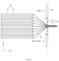
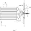
- FIGS. 2 to 4 are schematic views for explaining a configuration and an operation of an electrode tab welding device according to an embodiment of the present invention.
- FIG. 2 is a schematic view illustrating a state before a tab guide 100 gathers a plurality of electrode tabs 15
- FIG. 3 is a schematic view illustrating a state in which the plurality of electrode tabs 15 are gathered by the tab guide 100
- FIG. 4 is a schematic view illustrating a state in which the plurality of electrode tabs 15 are welded to each other by a welding part 50.
- the electrode tab welding device may weld the plurality of electrode tabs 15 provided in an electrode assembly 10 to each other.
- the electrode assembly 10 may be provided by alternately stacking a plurality of electrodes 11 and a plurality of separators 13.
- the plurality of electrodes 11 may include a positive electrode and a negative electrode, and the electrode tabs 15 may be connected to the electrodes 11, respectively.
- the drawings illustrate only a negative electrode tab connected to the negative electrode for convenience of explanation, it could be easily understood by those skilled in the art that a positive electrode tab connected to the positive electrode may be also provided in the electrode assembly 10 and welded in the same manner as the negative electrode tab.
- the electrode tab welding device may include the tab guide 100, which presses the plurality of electrode tabs 15 so that the plurality of electrode tabs are gathered together, and the welding part 50 which welds the plurality of electrode tabs 15 gathered by the tab guide 100 to each other.
- the tab guide 100 may be disposed at at least one side of the plurality of electrode tabs 15.
- the tab guide 100 may be provided in a pair to face each other with the plurality of electrode tabs 15 therebetween in a height direction (e.g., a direction parallel to a Z axis in FIG. 2 ) of the electrode assembly 10.
- the tab guides 100 may press the plurality of electrode tabs 15 at both sides, respectively.
- the pair of tab guides 100 may include a lower tab guide 100A, which is disposed at a lower side of the plurality of electrode tabs 15, and an upper tab guide 100B which is disposed at an upper side of the plurality of electrode tabs 15.
- a distance between the pair of tab guides 100 may be adjusted.
- at least one of the pair of tab guides 100 may be provided so as to be elevatable.
- the pair of tab guides 100 may approach each other and press the plurality of electrode tabs 15 to gather the plurality of electrode tabs 15.
- the pair of tab guides 100 may strongly press the plurality of electrode tabs 15.
- the tab guide 100 may be disposed at one side of the plurality of electrode tabs 15 and a general support (not shown) may be disposed at the other side.
- the welding part 50 may weld the plurality of electrode tabs 15 gathered by the tab guide 100 to each other. That is, the welding part 50 may weld the plurality of electrode tabs 15 to each other so as to form a portion to be welded 16.
- the welding part 50 may perform ultrasonic welding on the plurality of electrode tabs 15.
- the welding part 50 may include an anvil, which is disposed at one side (e.g., a lower side) of the plurality of electrode tabs 15, and a horn which is disposed at the other side (e.g., an upper side) of the plurality of electrode tabs 15.
- the welding part 50 may be configured so that a distance between the anvil and the horn is adjusted. In a state in which the plurality of electrode tabs 15 are pressed between the anvil and the horn, the horn may undergo the ultrasonic vibration and accordingly, the plurality of electrode tabs 15 may be welded to each other.
- the welding part 50 may be disposed to be farther away from the electrode assembly 10 than the pair of tab guides 100 are.
- the portion to be welded 16 may be farther away from the electrode assembly 10 than a point at which the pair of tab guides 30 press the plurality of electrode tabs 15 is.
- the electrode assembly 10, which is provided with the plurality of electrode tabs 15 welded to each other at the portion to be welded 16, may be manufactured through those processes.
- a pouch type battery may be manufactured by connecting an electrode lead to the plurality of electrode tabs 15 welded to each other and then accommodating the electrode assembly 10 in a pouch.
- the tab guide 100 may include a contact part 110, which is in contact with the electrode tabs 15, and a mounting part 120 in which the contact part 110 is detachably mounted and which has higher rigidity than that of the contact part 110.
- the contact part 110 is detachably mounted in the mounting part 120, maintenance and repair are possible by replacing the contact part 110 alone without a need to replace the entire tab guide 100 when abrasion or the like occurs at the contact part 110.
- costs of consumables of the tab guide 100 may be reduced, and the maintenance and repair of the tab guide 100 may be simplified.
- the mounting part 120 may have a material that has higher rigidity than a material of the contact part 110.
- the mounting part 120 may have a metal material, and the contact part 110 may have a non-metal material.
- the mounting part 120 may have a steel material.
- the contact part 110 may have a polyetheretherketone (PEEK) material.
- PEEK polyetheretherketone
- an embodiment of the present invention is not limited thereto, and the contact part 110 may have another material such as polyamide or alumina. Accordingly, due to the high rigidity of the mounting part 120, a concern that alignment of the tab guide 100 is misaligned may be minimized, and alignment of the contact part 110 may be reliably maintained when the contact part 110 is replaced in the mounting part 120.
- the contact part 110 may have a surface friction coefficient lower than a surface friction coefficient of the mounting part 120. Thus, a concern that the electrode tabs 15 are damaged by friction caused by the contact part 110 may be prevented.
- the surface friction coefficient of the contact part 110 may be 0.1 or less. This surface friction coefficient may be measured through DIN 53375 that is a known test.
- the surface friction coefficient of the contact part 110 may be 0.03 or higher, but is not limited thereto.
- the contact part 110 may have wear resistance lower than wear resistance of the mounting part 120. This is because the mounting part 120 has higher rigidity than that of the contact part 110 as describe above. However, when the wear resistance of the contact part 110 is too low, there is a problem that a replacement cycle of the contact part 110 is short to lead to an increase in consumption costs. Thus, preferably the material of the contact part 110 may have predetermined wear resistance.
- an abrasion loss of a material of the contact part 110 may be 0.15 g or less in a known ball-on-disk wear test.
- a condition that an abrasion loss of the disk is 0.15 g or less may be satisfied. If a material of the disk, of which an abrasion loss is 0.15 g or greater, is adopted as a material of the contact part 110, the contact part 110 has too low wear resistance and thus, is not suitable.
- the abrasion loss was measured to be 0.103 g when the material of the disk is polyamide, the abrasion loss was measured to be 0.001 g when the material of the disk is polyetheretherketone (PEEK), and the abrasion loss was measured to be 0.013 when the material of the disk is alumina. That is, polyetheretherketone, polyamide, or alumina may be selected as the material of the contact part 110. In contrasts, when the material of the disk is zirconia, the abrasion loss was measured to be 0.892. That is, zirconia is inappropriate as the material of the contact part 110.
- the contact part 110 may include a main body 111, which is detachably mounted on the mounting part 120, and a protrusion 112 which is connected to the main body 111 and protrudes toward the electrode tabs 15.
- the main body 111 and the protrusion 112 may be formed as one body.
- Each of the main body 111 and the protrusion 112 may have a predetermined thickness in a longitudinal direction (e.g., a direction parallel to an X axis in FIG. 2 ) of the electrode tabs 15.
- the protrusion 112 may have a smaller thickness than that of the main body 111.
- the main body 111 may have a first thickness t1
- the protrusion 112 may have a second thickness t2 smaller than the first thickness t1.
- the main body 111 As the main body 111 is formed to be relatively thick, the main body 111 may be stably mounted on the mounting part 120. As the protrusion 112 is formed to be relatively thin, the protrusion 112 may precisely press and gather the electrode tabs 115.
- the contact part 110 may be detachably coupled to the mounting part 120.
- a coupling projection 115 may be provided on one of the contact part 110 and the mounting part 120, and a coupling groove 125 that restricts the coupling projection 115 may be defined in the other of the contact part 110 and the mounting part 120.
- the coupling projection 115 is provided on the contact part 110 and the coupling groove 125 is defined in the mounting part 120.
- the tab guide 100 may extend to be parallel to a width direction of the electrode tabs 15.
- the coupling projection 115 and the coupling groove 125 may extend to be parallel to the width direction of the electrode tabs 15.
- the contact part 110 may be coupled to and detached from the mounting part 120 by moving in the width direction of the electrode tabs 15.
- the contact part 110 may be restricted by the mounting part 120 in a width direction and a height direction of the tab guide 100.
- the coupling projection 115 may include a projecting portion 116, which protrudes from the contact part 110 toward the mounting part 120, and a hooking portion 117 which protrudes from an end of the projecting portion 116 to each of both sides in a thickness direction.
- the coupling groove 125 may include a narrow groove portion 126, into which the projecting portion 116 is inserted, and a wide groove portion 127 into which the hooking portion 117 is inserted.
- the hooking portion 117 of the coupling projection 115 may not pass through the narrow groove portion 126 of the coupling groove 125 and be restricted in the height direction of the electrode assembly 100.
- FIGS. 5 and 6 are front views of a tab guide according to another embodiment of the present invention.
- FIG. 5 is a front view of a lower tab guide 100A among a pair of tab guides 100
- FIG. 6 is a front view of an upper tab guide 100B among the pair of tab guides 100.
- a height h2 of a mounting part 120 may be longer than a height h1 of a contact part 110.
- a width of the mounting part 120 and a width of the contact part 110 may be the same as or similar to each other.
- the mounting part 120 may have a size greater than that of the contact part 110. Accordingly, consumption costs of the contact part 110 may be reduced, and alignment of the contact part 110 may be more reliably maintained by the mounting part 120.
- a coupling hole 129 coupled to an elevating device (not shown), which elevates the tab guide 110, may be defined in the mounting part 120.
- the coupling hole 129 may be stably coupled to the elevating device through a coupling member such as a screw.
- a coupling member such as a screw
- Electrode assembly 11 Electrode 13: Separator 15: Electrode tab 16: Portion to be welded 50: Welding part 100: Tab guide 100A: Lower tab guide 100B: Upper tab guide 110: Contact part 111: Main body 112: Protrusion 115: Coupling projection 120: Mounting part 125: Coupling groove 129: Coupling hole
Landscapes
- Engineering & Computer Science (AREA)
- Mechanical Engineering (AREA)
- Chemical & Material Sciences (AREA)
- Chemical Kinetics & Catalysis (AREA)
- Electrochemistry (AREA)
- General Chemical & Material Sciences (AREA)
- Physics & Mathematics (AREA)
- Optics & Photonics (AREA)
- Connection Of Batteries Or Terminals (AREA)
- Pressure Welding/Diffusion-Bonding (AREA)
Applications Claiming Priority (3)
| Application Number | Priority Date | Filing Date | Title |
|---|---|---|---|
| KR20220010291 | 2022-01-24 | ||
| KR1020230005565A KR20230114200A (ko) | 2022-01-24 | 2023-01-13 | 탭 가이드 및 이를 포함하는 전극탭 용접 장치 |
| PCT/KR2023/000782 WO2023140588A1 (ko) | 2022-01-24 | 2023-01-17 | 탭 가이드 및 이를 포함하는 전극탭 용접 장치 |
Publications (2)
| Publication Number | Publication Date |
|---|---|
| EP4471920A1 true EP4471920A1 (de) | 2024-12-04 |
| EP4471920A4 EP4471920A4 (de) | 2025-05-14 |
Family
ID=87348976
Family Applications (1)
| Application Number | Title | Priority Date | Filing Date |
|---|---|---|---|
| EP23743435.2A Pending EP4471920A4 (de) | 2022-01-24 | 2023-01-17 | Laschenführung und elektrodenlaschenschweissvorrichtung damit |
Country Status (4)
| Country | Link |
|---|---|
| US (1) | US20250018496A1 (de) |
| EP (1) | EP4471920A4 (de) |
| JP (1) | JP7790646B2 (de) |
| WO (1) | WO2023140588A1 (de) |
Family Cites Families (13)
| Publication number | Priority date | Publication date | Assignee | Title |
|---|---|---|---|---|
| US2820495A (en) * | 1954-09-14 | 1958-01-21 | Wetzler Hedwig | Jaw faces for woodworking clamps |
| US3322423A (en) * | 1964-06-24 | 1967-05-30 | Popow Anatoliy | Vise jaw cover plate |
| US5143359A (en) * | 1991-05-13 | 1992-09-01 | Bush Matthew A | Swivel clamp guard |
| JP5157500B2 (ja) * | 2008-02-06 | 2013-03-06 | ソニー株式会社 | 非水電解質電池およびその製造方法 |
| CN106670992A (zh) * | 2015-11-05 | 2017-05-17 | 余姚市顺鼎贸易有限公司 | 一种工字型滑槽固定嵌入式结构 |
| KR102094210B1 (ko) * | 2016-02-12 | 2020-03-27 | 주식회사 엘지화학 | 레이저 용접된 전극 탭과 전극리드를 구비한 전지셀 |
| KR102234993B1 (ko) * | 2016-12-21 | 2021-04-01 | 주식회사 엘지화학 | 전지셀 및 이의 제조방법 |
| JP6930352B2 (ja) | 2017-10-04 | 2021-09-01 | 株式会社豊田自動織機 | 保護板溶接装置 |
| CN207431770U (zh) * | 2017-10-09 | 2018-06-01 | 新昌县镜岭镇凌康机械厂 | 一种可多角度移动的机械夹具 |
| JP2019207861A (ja) * | 2018-05-29 | 2019-12-05 | 株式会社豊田自動織機 | 蓄電装置の製造方法及び蓄電装置製造用の治具 |
| KR102739779B1 (ko) * | 2019-02-28 | 2024-12-09 | 주식회사 엘지에너지솔루션 | 전극 조립체 제조방법 및 전극 조립체 제조장치 |
| KR102808445B1 (ko) * | 2020-05-12 | 2025-05-16 | 주식회사 엘지에너지솔루션 | 전극 탭 용접 장치 및 방법 |
| KR102814405B1 (ko) | 2021-12-23 | 2025-05-29 | 주식회사 엘지에너지솔루션 | 전극탭 용접장치, 전극탭 용접방법 및 전극조립체 |
-
2023
- 2023-01-17 US US18/712,984 patent/US20250018496A1/en active Pending
- 2023-01-17 EP EP23743435.2A patent/EP4471920A4/de active Pending
- 2023-01-17 WO PCT/KR2023/000782 patent/WO2023140588A1/ko not_active Ceased
- 2023-01-17 JP JP2024541633A patent/JP7790646B2/ja active Active
Also Published As
| Publication number | Publication date |
|---|---|
| JP2025502877A (ja) | 2025-01-28 |
| WO2023140588A1 (ko) | 2023-07-27 |
| US20250018496A1 (en) | 2025-01-16 |
| JP7790646B2 (ja) | 2025-12-23 |
| EP4471920A4 (de) | 2025-05-14 |
Similar Documents
| Publication | Publication Date | Title |
|---|---|---|
| US11982686B2 (en) | Electrode lead gripper for pressure activation device | |
| US20190386283A1 (en) | Laser welding jig and laser welding device comprising same | |
| US20250050445A1 (en) | Processing mechanism and ultrasonic welding apparatus | |
| US20160099454A1 (en) | Flexible electrochemical device including electrically connected electrode assemblies | |
| EP4432456A1 (de) | Elektrodenlaschenschweissvorrichtung, elektrodenlaschenschweissverfahren und elektrodenanordnung | |
| US12491588B2 (en) | Welding positioning apparatus, battery production line, and welding method | |
| KR102043114B1 (ko) | 2차전지셀 전극리드탭의 용접 가이드 장치 | |
| US20260038982A1 (en) | Battery cell, battery pack, and electric device | |
| KR20190027528A (ko) | 파우치형 이차전지 | |
| US20100086850A1 (en) | Secondary battery with terminal plate | |
| EP4471920A1 (de) | Laschenführung und elektrodenlaschenschweissvorrichtung damit | |
| EP2309571A1 (de) | Sekundärbatterie | |
| CN118339689A (zh) | 接片引导件以及包括接片引导件的电极接片焊接装置 | |
| US20210384593A1 (en) | Secondary battery | |
| KR102851284B1 (ko) | 전극탭 및 전극탭의 절단방법 | |
| KR20230114200A (ko) | 탭 가이드 및 이를 포함하는 전극탭 용접 장치 | |
| US20120129043A1 (en) | Method for producing assembled battery and assembled battery | |
| US20200335734A1 (en) | Case for secondary battery, secondary battery, and battery module | |
| KR20230122984A (ko) | 전극 탭용 지그 조립체 및 그를 포함하는 전극 탭용 용접장치 | |
| US20230008194A1 (en) | Secondary Battery and Method for Manufacturing the Same | |
| KR101146401B1 (ko) | 이차 전지용 전극조립체 및 그 제조방법 | |
| US20250114881A1 (en) | Jig Assembly for Electrode Tab and Welding Device for Electrode Tab Including the Same | |
| EP4645404A1 (de) | Elektrodenherstellungsvorrichtung und batteriezellen mit dadurch hergestellten elektroden sowie batteriepack und fahrzeug mit batteriezellen | |
| EP4556419A1 (de) | Klebebandvorrichtung für sekundärbatterie und damit hergestellte sekundärbatterie | |
| US20260051599A1 (en) | Carrier for transporting secondary battery |
Legal Events
| Date | Code | Title | Description |
|---|---|---|---|
| STAA | Information on the status of an ep patent application or granted ep patent |
Free format text: STATUS: THE INTERNATIONAL PUBLICATION HAS BEEN MADE |
|
| PUAI | Public reference made under article 153(3) epc to a published international application that has entered the european phase |
Free format text: ORIGINAL CODE: 0009012 |
|
| STAA | Information on the status of an ep patent application or granted ep patent |
Free format text: STATUS: REQUEST FOR EXAMINATION WAS MADE |
|
| 17P | Request for examination filed |
Effective date: 20240514 |
|
| AK | Designated contracting states |
Kind code of ref document: A1 Designated state(s): AL AT BE BG CH CY CZ DE DK EE ES FI FR GB GR HR HU IE IS IT LI LT LU LV MC ME MK MT NL NO PL PT RO RS SE SI SK SM TR |
|
| DAV | Request for validation of the european patent (deleted) | ||
| DAX | Request for extension of the european patent (deleted) | ||
| A4 | Supplementary search report drawn up and despatched |
Effective date: 20250415 |
|
| RIC1 | Information provided on ipc code assigned before grant |
Ipc: B23K 101/36 20060101ALI20250409BHEP Ipc: H01M 50/54 20210101ALI20250409BHEP Ipc: H01M 50/536 20210101ALI20250409BHEP Ipc: B23K 20/10 20060101ALI20250409BHEP Ipc: H01M 10/04 20060101AFI20250409BHEP |
|
| STAA | Information on the status of an ep patent application or granted ep patent |
Free format text: STATUS: EXAMINATION IS IN PROGRESS |