EP4471454A2 - Randomisierte phasen- und amplitudenradarcodes zur raumobjektverfolgung - Google Patents
Randomisierte phasen- und amplitudenradarcodes zur raumobjektverfolgung Download PDFInfo
- Publication number
- EP4471454A2 EP4471454A2 EP24207342.7A EP24207342A EP4471454A2 EP 4471454 A2 EP4471454 A2 EP 4471454A2 EP 24207342 A EP24207342 A EP 24207342A EP 4471454 A2 EP4471454 A2 EP 4471454A2
- Authority
- EP
- European Patent Office
- Prior art keywords
- pulse train
- radar
- random distribution
- antenna
- tracking
- Prior art date
- Legal status (The legal status is an assumption and is not a legal conclusion. Google has not performed a legal analysis and makes no representation as to the accuracy of the status listed.)
- Pending
Links
Images


Classifications
-
- G—PHYSICS
- G01—MEASURING; TESTING
- G01S—RADIO DIRECTION-FINDING; RADIO NAVIGATION; DETERMINING DISTANCE OR VELOCITY BY USE OF RADIO WAVES; LOCATING OR PRESENCE-DETECTING BY USE OF THE REFLECTION OR RERADIATION OF RADIO WAVES; ANALOGOUS ARRANGEMENTS USING OTHER WAVES
- G01S13/00—Systems using the reflection or reradiation of radio waves, e.g. radar systems; Analogous systems using reflection or reradiation of waves whose nature or wavelength is irrelevant or unspecified
- G01S13/02—Systems using reflection of radio waves, e.g. primary radar systems; Analogous systems
- G01S13/06—Systems determining position data of a target
- G01S13/08—Systems for measuring distance only
- G01S13/10—Systems for measuring distance only using transmission of interrupted, pulse modulated waves
- G01S13/30—Systems for measuring distance only using transmission of interrupted, pulse modulated waves using more than one pulse per radar period
-
- G—PHYSICS
- G01—MEASURING; TESTING
- G01S—RADIO DIRECTION-FINDING; RADIO NAVIGATION; DETERMINING DISTANCE OR VELOCITY BY USE OF RADIO WAVES; LOCATING OR PRESENCE-DETECTING BY USE OF THE REFLECTION OR RERADIATION OF RADIO WAVES; ANALOGOUS ARRANGEMENTS USING OTHER WAVES
- G01S13/00—Systems using the reflection or reradiation of radio waves, e.g. radar systems; Analogous systems using reflection or reradiation of waves whose nature or wavelength is irrelevant or unspecified
- G01S13/66—Radar-tracking systems; Analogous systems
- G01S13/72—Radar-tracking systems; Analogous systems for two-dimensional [2D] tracking, e.g. combination of angle and range tracking, track-while-scan radar
- G01S13/723—Radar-tracking systems; Analogous systems for two-dimensional [2D] tracking, e.g. combination of angle and range tracking, track-while-scan radar by using numerical data
- G01S13/726—Multiple target tracking
-
- G—PHYSICS
- G01—MEASURING; TESTING
- G01S—RADIO DIRECTION-FINDING; RADIO NAVIGATION; DETERMINING DISTANCE OR VELOCITY BY USE OF RADIO WAVES; LOCATING OR PRESENCE-DETECTING BY USE OF THE REFLECTION OR RERADIATION OF RADIO WAVES; ANALOGOUS ARRANGEMENTS USING OTHER WAVES
- G01S13/00—Systems using the reflection or reradiation of radio waves, e.g. radar systems; Analogous systems using reflection or reradiation of waves whose nature or wavelength is irrelevant or unspecified
- G01S13/02—Systems using reflection of radio waves, e.g. primary radar systems; Analogous systems
- G01S13/06—Systems determining position data of a target
- G01S13/08—Systems for measuring distance only
- G01S13/10—Systems for measuring distance only using transmission of interrupted, pulse modulated waves
- G01S13/12—Systems for measuring distance only using transmission of interrupted, pulse modulated waves wherein the pulse-recurrence frequency is varied to provide a desired time relationship between the transmission of a pulse and the receipt of the echo of a preceding pulse
-
- G—PHYSICS
- G01—MEASURING; TESTING
- G01S—RADIO DIRECTION-FINDING; RADIO NAVIGATION; DETERMINING DISTANCE OR VELOCITY BY USE OF RADIO WAVES; LOCATING OR PRESENCE-DETECTING BY USE OF THE REFLECTION OR RERADIATION OF RADIO WAVES; ANALOGOUS ARRANGEMENTS USING OTHER WAVES
- G01S13/00—Systems using the reflection or reradiation of radio waves, e.g. radar systems; Analogous systems using reflection or reradiation of waves whose nature or wavelength is irrelevant or unspecified
- G01S13/02—Systems using reflection of radio waves, e.g. primary radar systems; Analogous systems
- G01S13/06—Systems determining position data of a target
- G01S13/08—Systems for measuring distance only
- G01S13/10—Systems for measuring distance only using transmission of interrupted, pulse modulated waves
- G01S13/26—Systems for measuring distance only using transmission of interrupted, pulse modulated waves wherein the transmitted pulses use a frequency- or phase-modulated carrier wave
- G01S13/28—Systems for measuring distance only using transmission of interrupted, pulse modulated waves wherein the transmitted pulses use a frequency- or phase-modulated carrier wave with time compression of received pulses
- G01S13/284—Systems for measuring distance only using transmission of interrupted, pulse modulated waves wherein the transmitted pulses use a frequency- or phase-modulated carrier wave with time compression of received pulses using coded pulses
- G01S13/288—Systems for measuring distance only using transmission of interrupted, pulse modulated waves wherein the transmitted pulses use a frequency- or phase-modulated carrier wave with time compression of received pulses using coded pulses phase modulated
-
- G—PHYSICS
- G01—MEASURING; TESTING
- G01S—RADIO DIRECTION-FINDING; RADIO NAVIGATION; DETERMINING DISTANCE OR VELOCITY BY USE OF RADIO WAVES; LOCATING OR PRESENCE-DETECTING BY USE OF THE REFLECTION OR RERADIATION OF RADIO WAVES; ANALOGOUS ARRANGEMENTS USING OTHER WAVES
- G01S13/00—Systems using the reflection or reradiation of radio waves, e.g. radar systems; Analogous systems using reflection or reradiation of waves whose nature or wavelength is irrelevant or unspecified
- G01S13/02—Systems using reflection of radio waves, e.g. primary radar systems; Analogous systems
- G01S13/50—Systems of measurement based on relative movement of target
- G01S13/58—Velocity or trajectory determination systems; Sense-of-movement determination systems
- G01S13/581—Velocity or trajectory determination systems; Sense-of-movement determination systems using transmission of interrupted pulse modulated waves and based upon the Doppler effect resulting from movement of targets
- G01S13/582—Velocity or trajectory determination systems; Sense-of-movement determination systems using transmission of interrupted pulse modulated waves and based upon the Doppler effect resulting from movement of targets adapted for simultaneous range and velocity measurements
-
- G—PHYSICS
- G01—MEASURING; TESTING
- G01S—RADIO DIRECTION-FINDING; RADIO NAVIGATION; DETERMINING DISTANCE OR VELOCITY BY USE OF RADIO WAVES; LOCATING OR PRESENCE-DETECTING BY USE OF THE REFLECTION OR RERADIATION OF RADIO WAVES; ANALOGOUS ARRANGEMENTS USING OTHER WAVES
- G01S13/00—Systems using the reflection or reradiation of radio waves, e.g. radar systems; Analogous systems using reflection or reradiation of waves whose nature or wavelength is irrelevant or unspecified
- G01S13/66—Radar-tracking systems; Analogous systems
-
- G—PHYSICS
- G01—MEASURING; TESTING
- G01S—RADIO DIRECTION-FINDING; RADIO NAVIGATION; DETERMINING DISTANCE OR VELOCITY BY USE OF RADIO WAVES; LOCATING OR PRESENCE-DETECTING BY USE OF THE REFLECTION OR RERADIATION OF RADIO WAVES; ANALOGOUS ARRANGEMENTS USING OTHER WAVES
- G01S13/00—Systems using the reflection or reradiation of radio waves, e.g. radar systems; Analogous systems using reflection or reradiation of waves whose nature or wavelength is irrelevant or unspecified
- G01S13/02—Systems using reflection of radio waves, e.g. primary radar systems; Analogous systems
- G01S13/06—Systems determining position data of a target
- G01S13/08—Systems for measuring distance only
- G01S13/10—Systems for measuring distance only using transmission of interrupted, pulse modulated waves
- G01S13/106—Systems for measuring distance only using transmission of interrupted, pulse modulated waves using transmission of pulses having some particular characteristics
-
- G—PHYSICS
- G01—MEASURING; TESTING
- G01S—RADIO DIRECTION-FINDING; RADIO NAVIGATION; DETERMINING DISTANCE OR VELOCITY BY USE OF RADIO WAVES; LOCATING OR PRESENCE-DETECTING BY USE OF THE REFLECTION OR RERADIATION OF RADIO WAVES; ANALOGOUS ARRANGEMENTS USING OTHER WAVES
- G01S13/00—Systems using the reflection or reradiation of radio waves, e.g. radar systems; Analogous systems using reflection or reradiation of waves whose nature or wavelength is irrelevant or unspecified
- G01S13/02—Systems using reflection of radio waves, e.g. primary radar systems; Analogous systems
- G01S13/06—Systems determining position data of a target
- G01S13/08—Systems for measuring distance only
- G01S13/10—Systems for measuring distance only using transmission of interrupted, pulse modulated waves
- G01S13/22—Systems for measuring distance only using transmission of interrupted, pulse modulated waves using irregular pulse repetition frequency
- G01S13/222—Systems for measuring distance only using transmission of interrupted, pulse modulated waves using irregular pulse repetition frequency using random or pseudorandom pulse repetition frequency
-
- G—PHYSICS
- G01—MEASURING; TESTING
- G01S—RADIO DIRECTION-FINDING; RADIO NAVIGATION; DETERMINING DISTANCE OR VELOCITY BY USE OF RADIO WAVES; LOCATING OR PRESENCE-DETECTING BY USE OF THE REFLECTION OR RERADIATION OF RADIO WAVES; ANALOGOUS ARRANGEMENTS USING OTHER WAVES
- G01S13/00—Systems using the reflection or reradiation of radio waves, e.g. radar systems; Analogous systems using reflection or reradiation of waves whose nature or wavelength is irrelevant or unspecified
- G01S13/02—Systems using reflection of radio waves, e.g. primary radar systems; Analogous systems
- G01S2013/0236—Special technical features
- G01S2013/0245—Radar with phased array antenna
- G01S2013/0254—Active array antenna
-
- G—PHYSICS
- G01—MEASURING; TESTING
- G01S—RADIO DIRECTION-FINDING; RADIO NAVIGATION; DETERMINING DISTANCE OR VELOCITY BY USE OF RADIO WAVES; LOCATING OR PRESENCE-DETECTING BY USE OF THE REFLECTION OR RERADIATION OF RADIO WAVES; ANALOGOUS ARRANGEMENTS USING OTHER WAVES
- G01S7/00—Details of systems according to groups G01S13/00, G01S15/00, G01S17/00
- G01S7/02—Details of systems according to groups G01S13/00, G01S15/00, G01S17/00 of systems according to group G01S13/00
- G01S7/28—Details of pulse systems
- G01S7/2806—Employing storage or delay devices which preserve the pulse form of the echo signal, e.g. for comparing and combining echoes received during different periods
Definitions
- LEO Low Earth Orbit
- Some radars detect and track space objects, such as space debris and satellites, primarily in Low Earth Orbit (LEO).
- Low Earth Orbit typically refers to distances from the Earth's surface to 2,000 kilometers away, but that is just an example with no limitation to that definition intended.
- Most satellites and the International Space Station operate in LEO, which makes tracking of debris and other objects even more important.
- the desired operation would be integrated measurements of the space object over long periods of time.
- High Doppler resolution means that the radar can detect objects that travel relatively close together.
- long periods of time may run several hundreds of milliseconds or longer. These long periods of time conflict with the transmission limitations required to resolve the distance to the target, which may range from a few hundred to a few thousand kilometers.
- One embodiment is a method of tracking objects using a radar, that includes sending a beamcode to at least one radar antenna to set a predetermined direction, using samples from a random distribution of at least one of a phase or an amplitude to generate a tracking signal pulse train, transmitting the pulse train from the at least one antenna within a pulse time window, receiving return signals from objects at the at least one antenna, and using the return signals to gather data to track the objects.
- Another embodiment is a radar system having at least one radar antenna to transmit a tracking signal, a memory to store a set of random distributions, a controller connected to the at least one radar antenna and the memory, the controller to execute instructions to determine which random distribution to use, generate a pulse train using the random distribution, transmit the pulse train to the at least one radar antenna as the tracking signal, and gather measurement data about objects returning signals from the tracking signal.
- the term "radar” means any system used to perform radio detection and ranging. It may take the form of a parabolic reflector, planar array, phased antenna arrays, and other examples, having a transmitter and a receiver.
- An “antenna” consists of the radiating element or elements that radiate radio signals generated by the transmitter and receives radio signals and pass them to the receiver.
- a “beamcode” is a signal sent to at least one antenna to provide a predetermined direction in which a transmission is to be sent.
- a “tracking signal” or “tracking transmission” is a signal sent by the antenna into the predetermined direction with the intent of receiving return signals from objects in free space into which the tracking transmission was sent.
- a “return signal” is a signal caused by the tracking signal reflecting off an object in free space and returned to the antenna.
- the embodiments in here employ pulses sampled from uniform, random “distributions” as the tracking or transmitted signal.
- the random samples may also be referred to as a "code,” or a "waveform.”
- Some embodiments may use non-uniform, random distributions.
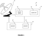
- FIG. 1 shows an embodiment of a radar system 10 usable with the methods and techniques discussed here.
- the radar system has a controller 12, which may reside inside the radar transmitter, receiver, or a combined transmitter/receiver.
- the radar may consist of a phased array of antenna elements, where each element has its own controller, or the elements are divided into sub-arrays, each sub-array having a controller.
- the controller may include dedicated control hardware or components 16 for controlling the antenna array and transmitter/receiver, and a separate computer 14 for selection of random distributions used by the embodiments here.
- the radar control and the computer may reside in the same device, or separate devices, within the system.
- the embodiments here use random distributions that may be stored in a memory such as 20. These may be stored in a separate memory 22 from the memory used for transmission and reception 24, or they may share a common memory.
- radars used for tracking low earth objects generate a series of periodic pulses sent into space.
- performance parameters may include a maximum pulse width, a minimum pulse width, duty cycle, beamcode times, beamcode wait times, transmit/receiving padding, individual pulse length, interpulse period (IPP), among others.
- atypical pulse may have a duration between 10 microseconds and 2 milliseconds.
- one pulse is sent during that time, and several pulses are integrated over several pulse widths to allow reception of a number of return signals to provide accurate tracking.
- the embodiments here use a pulse train transmitted according to a uniform, random distribution. This allows multiple pulses of received returns to be integrated.
- Figure 2 shows an example of such a pulse train.
- the top line shows the beamcode transmission.
- Each beamcode corresponds to a single look direction.
- the beamcode BM is transmitted at the beginning of the pulse interval, t 0 until the end of the transmission time, t beamcode .
- a pulse train is then sent between t wait and the end of the pulse train interval t pt .
- the pulse train interval may also be referred to as the pulse train window.
- each pulse has constant amplitude but is coded with a phase drawn from a uniform random distribution (not shown), typically polyphase. Individual pulse length and IPPs are also drawn from the random distribution.
- Figure 3 shows a comparison between a traditional waveform shown by pulses 24 and the pulse train, shown by the varied pulses such as 26.
- the traditional waveform used as an example here has a 2 millisecond pulse with a 20 millisecond IPP.
- the waveform shown by the randomized pulses such as 26 is the RF waveform. Within the transmission envelope, it is coded with a random polyphase code (not shown).
- Figure 4 shows an embodiment of a process of generating the pulse train and the selection of random samples.
- the main flow of the process relates to the generation of the pulse train.
- the beamcode for a predetermined single look direction is transmitted to the antenna to cause the antenna to orient itself into the proper direction, which can be done with either electronic, as in a phased array, or mechanical steering, as in a moveable antenna.
- a uniform, random distribution is used to generate a tracking signal pulse train such as the one shown in Figures 2 and 3 .
- the radar transmits the pulse train at 34 and receives the return signals at 36. The reception occurs continuously throughout the process.
- the random code to vary the phase of the transmission signal, the received signal from each pulse can be distinguished from each other.
- the random samples are selected based on examination of the waveform sidelobes.
- the process generates a pulse train. For example, the process may generate a set of random pulses within the minimum and maximum pulse lengths, a set of random duty cycles within a minimum and maximum duty cycles, and use these to form a pulse train.
- a number of samples in the receiving time, or window, that are unusable due to transmitting is determined.
- a transmitting signal will saturate any received signal that falls within the transmit window of the transmitting signal. This results in an efficiency measure that equals the number of usable samples divided by the total number of samples. This is then used to determine the efficiency of that pulse train previously generated.
- Figure 5 shows an example of the efficiency of a waveform.
- the top graph shows the number of pulses integrated as a function of the relative sample time, which corresponds to the time-of-flight to a target.
- the solid line 49 shows the ideal case, if all pulses were integrated.
- the ratio of the number of pulses integrated to the number of pulses transmitted corresponds to the efficiency percentage in the lower graph.
- the embodiments here result in an efficiency of 80-90%, meaning that at a given time-of-flight (range) 80-90% of the samples can be integrated for measurement of the target.
- the process determines the peak sidelobe level at 46. Generally, this determination occurs based upon the largest sidelobe in frequency space.
- the efficiency measure and the peak sidelobe level will define a metric at 48.
- the metric attempts to maximize the efficiency while minimizing the peak sidelobe level. Using this metric, the process chooses the code with the best metric in one embodiment.
- Another embodiment may define a desired efficiency and find the distribution that matches that efficiency. Multiple iterations may occur until the desired efficiency is achieved.
- the resulting code, or distribution, that meets the criteria established as the desired characteristic will then be used to generate the transmission pulse train.
- a variety of search methods may be used to find the optimal transmission sequence for a given application.
- parameters of the pulse train may be used to define a metric. These parameters may include, but are not limited to, the integrated sidelobe level, the main lobe width, and the total power in the main lobe
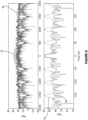
- Figure 6 shows a comparison of the power spectral density of a currently-used waveform, and a waveform using the embodiments discussed here.
- the top graph has a scale that is 100 times the scale of the bottom graph, and provides a wider view of the comparison.
- the traces 50 result from the embodiments discussed here.
- the traces 52 result from the traditional constant pulse length that has a pulse length time, and IPP.
- a first example has the following operating parameters.
- the center frequency resides at 440 MHz, but is adjustable as needed.
- the beamcode message is 16-bits with a first bit that is always high, and each bit is 2 microseconds for a total duration of 32 microseconds.
- the beamcode wait time is 400 microseconds, the system waits 400 microseconds after beamcode transmission.
- the transmission from the power waveform to the radio frequency (RF) involves delays, so the system requires transmit and receive padding.
- RF radio frequency
- a lead pad consists of a 2 microsecond at the beginning of each transmit and receive interval. This ensures that the transmit/receive arrives before the RF.
- the trailing pad is 10 microseconds at the end of each interval. This ensures that the RF signal before gating turns off.
- the individual pulse length is drawn from the random distributions discussed above, in this example the range is from 100 microseconds to 500 microseconds, but can be adjusted anywhere within the transmit limits.
- the duty cycle for each pulse is drawn from a distribution, and may range from 5% and 20% while trending towards an average duty cycle of 10%. These values could be adjusted within the range of the solid-state power amplifier (SSPA) subject to performance limits.
- SSPA solid-state power amplifier
- the baud length, the baud duration within a pulse is nominally set at 0.5 microseconds, 2 MHz, but could be increased.
- the phase for each baud is drawn from the random distribution of the entire unit circle. Alternatively, a binary phase could also be used.
- the pulse train duration is set by the maximum integration time desired for a single look direction. Nominally, this is set at 100 milliseconds for this particular embodiment, but can be adjusted. This time also determines the nominal Doppler resolution, a 100-microsecond integration time gives a 10 Hz (3.3 m/s) Doppler resolution.
- a non-transmit receive window can be left at the end of the pulse train, which should correspond to the maximum range desired. In one embodiment, this is set at 20 milliseconds.
- the average RF duty cycle over an entire pulse train should not exceed the SSPA limits, around 10% dependent upon current and temperature.
- the center frequency is approximately 2950 MHz.
- the beamcode message is 16 bits, at 1 microsecond, for a total duration of 16 microseconds.
- the beamcode waiting time takes 20 microseconds.
- the lead transmit/receive padding is 2 microseconds, and the trail pad is 2 microseconds.
- the individual pulse length is a random distribution between 100 to 500 microseconds, adjustable as needed. Generally, longer pulses are better for unambiguous range measurements and reduced short-range clutter but shorter pulses are better for Doppler measurements and decoding.
- the duty cycle random distribution ranges from 10% to 30% but trends toward an average duty cycle of 10%.
- the baud duration within a pulse will be set at 0.25 microseconds (4 MHz), but can be increased.
- the pulse train duration is set by the maximum integration time desired for a single look direction. This is initially set at 100 milliseconds, but is adjustable. A 100-millisecond integration time gives a 10 Hz (0.5 m/s) Doppler resolution. Similar to the embodiment above, the limits of SSPA, determined by current and temperature.
- a radar can transmit pulse trains in the place of the single pulses currently being used. This increases the efficiency of the radar and provides better resolution than current radars by reducing the Doppler ambiguity.
Landscapes
- Engineering & Computer Science (AREA)
- Radar, Positioning & Navigation (AREA)
- Remote Sensing (AREA)
- Computer Networks & Wireless Communication (AREA)
- Physics & Mathematics (AREA)
- General Physics & Mathematics (AREA)
- Radar Systems Or Details Thereof (AREA)
Applications Claiming Priority (3)
| Application Number | Priority Date | Filing Date | Title |
|---|---|---|---|
| US15/787,475 US10698099B2 (en) | 2017-10-18 | 2017-10-18 | Randomized phase and amplitude radar codes for space object tracking |
| PCT/US2018/055812 WO2019079151A1 (en) | 2017-10-18 | 2018-10-15 | RANDOMIZED PHASE AND AMPLITUDE RADAR CODES FOR TRACKING A SPATIAL OBJECT |
| EP18867699.3A EP3698165B1 (de) | 2017-10-18 | 2018-10-15 | Randomisierte phasen- und amplitudenradarcodes für raumobjektverfolgung |
Related Parent Applications (2)
| Application Number | Title | Priority Date | Filing Date |
|---|---|---|---|
| EP18867699.3A Division EP3698165B1 (de) | 2017-10-18 | 2018-10-15 | Randomisierte phasen- und amplitudenradarcodes für raumobjektverfolgung |
| EP18867699.3A Division-Into EP3698165B1 (de) | 2017-10-18 | 2018-10-15 | Randomisierte phasen- und amplitudenradarcodes für raumobjektverfolgung |
Publications (2)
| Publication Number | Publication Date |
|---|---|
| EP4471454A2 true EP4471454A2 (de) | 2024-12-04 |
| EP4471454A3 EP4471454A3 (de) | 2025-03-05 |
Family
ID=66096477
Family Applications (2)
| Application Number | Title | Priority Date | Filing Date |
|---|---|---|---|
| EP24207342.7A Pending EP4471454A3 (de) | 2017-10-18 | 2018-10-15 | Randomisierte phasen- und amplitudenradarcodes zur raumobjektverfolgung |
| EP18867699.3A Active EP3698165B1 (de) | 2017-10-18 | 2018-10-15 | Randomisierte phasen- und amplitudenradarcodes für raumobjektverfolgung |
Family Applications After (1)
| Application Number | Title | Priority Date | Filing Date |
|---|---|---|---|
| EP18867699.3A Active EP3698165B1 (de) | 2017-10-18 | 2018-10-15 | Randomisierte phasen- und amplitudenradarcodes für raumobjektverfolgung |
Country Status (8)
| Country | Link |
|---|---|
| US (2) | US10698099B2 (de) |
| EP (2) | EP4471454A3 (de) |
| JP (1) | JP7285849B2 (de) |
| AR (2) | AR113366A1 (de) |
| AU (1) | AU2018350835B2 (de) |
| CA (1) | CA3073753A1 (de) |
| NZ (1) | NZ762773A (de) |
| WO (1) | WO2019079151A1 (de) |
Families Citing this family (5)
| Publication number | Priority date | Publication date | Assignee | Title |
|---|---|---|---|---|
| US10698099B2 (en) * | 2017-10-18 | 2020-06-30 | Leolabs, Inc. | Randomized phase and amplitude radar codes for space object tracking |
| CN111474528B (zh) * | 2020-05-14 | 2021-03-16 | 中国电子科技集团公司第二十八研究所 | 一种用于终端区的目标复合跟踪系统精确栅格锁定方法 |
| EP4148452A1 (de) | 2021-09-10 | 2023-03-15 | Nxp B.V. | Radarsystem und radarverfahren zur wiedergabe widerstandsfähiger radaroperationen |
| CN113791405B (zh) * | 2021-09-15 | 2024-05-07 | 电子科技大学长三角研究院(衢州) | 一种基于正交二相编码信号的雷达解模糊及遮挡的方法 |
| CN115103410B (zh) * | 2022-08-22 | 2022-11-08 | 中国人民解放军国防科技大学 | 一种测控数传资源调度方法、系统及装置 |
Family Cites Families (46)
| Publication number | Priority date | Publication date | Assignee | Title |
|---|---|---|---|---|
| US2471284A (en) | 1945-05-25 | 1949-05-24 | Bell Telephone Labor Inc | Directive antenna system |
| US2969542A (en) | 1959-03-30 | 1961-01-24 | Coleman Henri Paris | Spiral antenna system with trough reflector |
| US3612845A (en) * | 1968-07-05 | 1971-10-12 | Reed C Lawlor | Computer utilizing random pulse trains |
| US4500882A (en) | 1980-11-05 | 1985-02-19 | Mitsubishi Denki Kabushiki Kaisha | Antenna system |
| US4780726A (en) | 1984-12-03 | 1988-10-25 | Trw Inc. | Depolyable reflector |
| US4769777A (en) * | 1986-06-25 | 1988-09-06 | General Electric Company | Unpredictable bit stream generator |
| US5130718A (en) | 1990-10-23 | 1992-07-14 | Hughes Aircraft Company | Multiple dichroic surface cassegrain reflector |
| US5115246A (en) | 1991-02-27 | 1992-05-19 | The United States Of America As Represented By The Secretary Of The Air Force | Radar target locating and tracking apparatus using a dual-interleaved pulse train radar waveform |
| US5570307A (en) * | 1995-01-06 | 1996-10-29 | Vlsi Technology, Inc. | Digital randomizer for on-chip generation and storage of random self-programming data block |
| US5748140A (en) | 1996-03-28 | 1998-05-05 | Hughes Electronics | System for tracking radar targets in background clutter |
| US5719579A (en) * | 1996-05-30 | 1998-02-17 | Esco Electronics Corporation | Virtual noise radar waveform for reduced radar detectability |
| JPH10213649A (ja) * | 1997-01-28 | 1998-08-11 | Tech Res & Dev Inst Of Japan Def Agency | レーダ試験用遠隔制御装置 |
| GB2326284A (en) | 1997-06-11 | 1998-12-16 | Siemens Plessey Electronic | Wide bandwidth antenna arrays |
| US5847677A (en) * | 1997-07-07 | 1998-12-08 | The United States Of America As Represented By The Secretary Of The Army | Random number generator for jittered pulse repetition interval radar systems |
| JP2942923B2 (ja) * | 1997-11-27 | 1999-08-30 | 株式会社ジーデイーエス | ランダムパルス型レーダー装置 |
| US6271786B1 (en) | 1999-06-07 | 2001-08-07 | Raytheon Company | Random noise radar target detection device |
| NL1012373C2 (nl) * | 1999-06-17 | 2000-12-19 | Hollandse Signaalapparaten Bv | Radarapparaat. |
| US6169522B1 (en) | 1999-09-03 | 2001-01-02 | Motorola, Inc. | Combined mechanical scanning and digital beamforming antenna |
| US6320553B1 (en) | 1999-12-14 | 2001-11-20 | Harris Corporation | Multiple frequency reflector antenna with multiple feeds |
| US6522210B1 (en) * | 2000-02-16 | 2003-02-18 | Honeywell International Inc. | Random pulse generator |
| US6823170B1 (en) | 2000-07-26 | 2004-11-23 | Ericsson Inc. | Satellite communications system using multiple earth stations |
| WO2002031915A2 (en) | 2000-10-13 | 2002-04-18 | Motorola, Inc. | Tracking antenna and method |
| US6664939B1 (en) | 2001-03-28 | 2003-12-16 | Mark Olinyk | Foam-filled antenna and method of manufacturing same |
| US6456231B1 (en) * | 2001-06-01 | 2002-09-24 | Mcewan Technologies, Llc | Radar sensor having a CFAR detector |
| US6862605B2 (en) * | 2001-08-15 | 2005-03-01 | Scott A. Wilber | True random number generator and entropy calculation device and method |
| US7123876B2 (en) | 2001-11-01 | 2006-10-17 | Motia | Easy set-up, vehicle mounted, in-motion tracking, satellite antenna |
| GB2397957A (en) | 2003-01-30 | 2004-08-04 | Qinetiq Ltd | Target detection |
| US6914554B1 (en) | 2003-10-17 | 2005-07-05 | The United States Of America As Represented By The Secretary Of The Army | Radar beam steering with remote reflectors/refractors |
| JP3894495B2 (ja) * | 2003-11-28 | 2007-03-22 | 三菱電機株式会社 | ビーム走査方法及びレーダー装置 |
| US6965351B1 (en) | 2004-03-29 | 2005-11-15 | Lockheed Martin Corporation | Dual-frequency-illuminating reflector |
| JP2005351811A (ja) * | 2004-06-11 | 2005-12-22 | Mitsubishi Electric Corp | 危険物探知装置 |
| US6933888B1 (en) | 2004-06-14 | 2005-08-23 | Bae Systems Information And Electronic Systems Integration Inc. | Multi-ship coherent geolocation system |
| US7250902B2 (en) * | 2005-07-19 | 2007-07-31 | Raytheon Company | Method of generating accurate estimates of azimuth and elevation angles of a target for a phased—phased array rotating radar |
| US7375676B1 (en) | 2006-03-07 | 2008-05-20 | Lockheed Martin Corporation | Mutual interference processor for pulse radar |
| CA2680849A1 (en) | 2007-03-16 | 2008-09-25 | Mobile Sat Ltd. | A vehicle mounted antenna and methods for transmitting and/or receiving signals |
| JP2009068896A (ja) * | 2007-09-11 | 2009-04-02 | Fuji Heavy Ind Ltd | 等価時間サンプリングレーダ |
| DE602008002824D1 (de) * | 2008-05-23 | 2010-11-11 | Thales Nederland Bv | Verfahren zur Schätzung der Position und der Geschwindigkeit eines Ziels mit einem Radar, der eine OFDM-Welle aussendet |
| US8378878B2 (en) | 2010-08-05 | 2013-02-19 | ARETé ASSOCIATES | Creating and processing universal radar waveforms |
| EP2637253A4 (de) | 2011-12-29 | 2014-12-17 | Quantrill Estate Inc | Universelle vorrichtung für energiekonzentration |
| US9075138B2 (en) * | 2012-04-23 | 2015-07-07 | Massachusetts Institute Of Technology | Efficient pulse Doppler radar with no blind ranges, range ambiguities, blind speeds, or Doppler ambiguities |
| US20140225796A1 (en) | 2013-02-08 | 2014-08-14 | Chien-An Chen | Ultra-broadband offset cassegrain dichroic antenna system for bidirectional satellite signal communication |
| AU2014288997B2 (en) | 2013-07-10 | 2017-11-09 | Bae Systems Plc | Interference nulling of multipath signals in stacked beam pulse radar |
| JP6147617B2 (ja) * | 2013-09-09 | 2017-06-14 | 株式会社東芝 | レーダ装置及びその信号処理方法 |
| US9761049B2 (en) | 2014-03-28 | 2017-09-12 | Intel Corporation | Determination of mobile display position and orientation using micropower impulse radar |
| AU2016246770B2 (en) | 2015-04-08 | 2020-07-16 | Sri International | 1D phased array antenna for radar and communications |
| US10698099B2 (en) * | 2017-10-18 | 2020-06-30 | Leolabs, Inc. | Randomized phase and amplitude radar codes for space object tracking |
-
2017
- 2017-10-18 US US15/787,475 patent/US10698099B2/en active Active
-
2018
- 2018-10-15 AU AU2018350835A patent/AU2018350835B2/en active Active
- 2018-10-15 EP EP24207342.7A patent/EP4471454A3/de active Pending
- 2018-10-15 WO PCT/US2018/055812 patent/WO2019079151A1/en not_active Ceased
- 2018-10-15 NZ NZ762773A patent/NZ762773A/en unknown
- 2018-10-15 EP EP18867699.3A patent/EP3698165B1/de active Active
- 2018-10-15 JP JP2020542531A patent/JP7285849B2/ja active Active
- 2018-10-15 CA CA3073753A patent/CA3073753A1/en active Pending
- 2018-10-17 AR ARP180103024A patent/AR113366A1/es active IP Right Grant
-
2020
- 2020-06-09 US US16/896,882 patent/US11327168B2/en active Active
-
2021
- 2021-12-22 AR ARP210103626A patent/AR124474A2/es not_active Application Discontinuation
Also Published As
| Publication number | Publication date |
|---|---|
| US20200363523A1 (en) | 2020-11-19 |
| US11327168B2 (en) | 2022-05-10 |
| JP7285849B2 (ja) | 2023-06-02 |
| AR113366A1 (es) | 2020-04-22 |
| EP3698165A1 (de) | 2020-08-26 |
| NZ762773A (en) | 2026-02-27 |
| WO2019079151A1 (en) | 2019-04-25 |
| AU2018350835A1 (en) | 2020-05-21 |
| AR124474A2 (es) | 2023-03-29 |
| EP3698165A4 (de) | 2021-07-07 |
| EP4471454A3 (de) | 2025-03-05 |
| US20190113611A1 (en) | 2019-04-18 |
| EP3698165B1 (de) | 2024-11-27 |
| CA3073753A1 (en) | 2019-04-25 |
| EP3698165C0 (de) | 2024-11-27 |
| AU2018350835B2 (en) | 2023-10-05 |
| JP2021500582A (ja) | 2021-01-07 |
| US10698099B2 (en) | 2020-06-30 |
Similar Documents
| Publication | Publication Date | Title |
|---|---|---|
| US11327168B2 (en) | Randomized phase and amplitude radar codes for space object tracking | |
| CN101430378B (zh) | 实现目标体方向的精确检测的车辆安装方向检测设备 | |
| CN104011558B (zh) | 编码的孔径波束分析方法和设备 | |
| EP1969392A2 (de) | Zeitduplexvorrichtung und verfahren für radarsensor-frontends | |
| WO2009143358A1 (en) | Split aperture array for increased short range target coverage | |
| US6639546B1 (en) | Radar system in which range ambiguity and range eclipsing are reduced by frequency diversity and alternation of pulse periodicity | |
| CN102680975A (zh) | 一种天基步进频分时测角雷达空间非合作目标成像方法 | |
| Wang et al. | Space-time coding technique for coherent frequency diverse array | |
| CN118202274A (zh) | 检测行人的雷达系统、方法和车辆 | |
| US20060273948A1 (en) | Selectable range lobes using wide-band array | |
| RU2375723C2 (ru) | Радиолокационный запросчик системы активного запроса-ответа | |
| JP7306891B2 (ja) | レーダ装置およびレーダ装置の対象物検出方法 | |
| JP4723880B2 (ja) | 電波誘導装置 | |
| US20240393447A1 (en) | A UWB radar device | |
| JP4879761B2 (ja) | レーダ装置 | |
| JP2005091174A (ja) | レーダ装置 | |
| RU2474841C2 (ru) | Способ радиолокационного обзора пространства и устройство для осуществления этого способа | |
| Jianqi et al. | Researches of a new kind of advanced meter wave radar | |
| RU2760409C1 (ru) | Способ обработки радиолокационных сигналов в импульсно-доплеровской радиолокационной станции с активной фазированной антенной решеткой | |
| US20250251492A1 (en) | Sub-Nyquist Hyperbolic Frequency Modulated Pulsed Radar for Accurate Range and Doppler Estimation | |
| RU2149422C1 (ru) | Кодовый дальномер для импульсно-доплеровской радиолокационной станции | |
| JP4660437B2 (ja) | 測高レーダ装置 | |
| Harper | Solid state phased array radar | |
| Gigleux et al. | Waveform with Time and Frequency Interruptions to Reduce the Energy Consumption of a Tracking Radar | |
| Shahid et al. | Design and implementation of multi mode Radar Target simulator using Direct Digital Synthesizer |
Legal Events
| Date | Code | Title | Description |
|---|---|---|---|
| PUAI | Public reference made under article 153(3) epc to a published international application that has entered the european phase |
Free format text: ORIGINAL CODE: 0009012 |
|
| STAA | Information on the status of an ep patent application or granted ep patent |
Free format text: STATUS: THE APPLICATION HAS BEEN PUBLISHED |
|
| AC | Divisional application: reference to earlier application |
Ref document number: 3698165 Country of ref document: EP Kind code of ref document: P |
|
| AK | Designated contracting states |
Kind code of ref document: A2 Designated state(s): AL AT BE BG CH CY CZ DE DK EE ES FI FR GB GR HR HU IE IS IT LI LT LU LV MC MK MT NL NO PL PT RO RS SE SI SK SM TR |
|
| REG | Reference to a national code |
Ref country code: DE Ref legal event code: R079 Free format text: PREVIOUS MAIN CLASS: G01S0013280000 Ipc: G01S0013660000 |
|
| PUAL | Search report despatched |
Free format text: ORIGINAL CODE: 0009013 |
|
| AK | Designated contracting states |
Kind code of ref document: A3 Designated state(s): AL AT BE BG CH CY CZ DE DK EE ES FI FR GB GR HR HU IE IS IT LI LT LU LV MC MK MT NL NO PL PT RO RS SE SI SK SM TR |
|
| RIC1 | Information provided on ipc code assigned before grant |
Ipc: G01S 7/28 20060101ALN20250128BHEP Ipc: G01S 13/28 20060101ALI20250128BHEP Ipc: G01S 13/58 20060101ALI20250128BHEP Ipc: G01S 13/30 20060101ALI20250128BHEP Ipc: G01S 13/22 20060101ALI20250128BHEP Ipc: G01S 13/12 20060101ALI20250128BHEP Ipc: G01S 13/72 20060101ALI20250128BHEP Ipc: G01S 13/04 20060101ALI20250128BHEP Ipc: G01S 7/41 20060101ALI20250128BHEP Ipc: G01S 13/02 20060101ALI20250128BHEP Ipc: G01S 13/66 20060101AFI20250128BHEP |
|
| STAA | Information on the status of an ep patent application or granted ep patent |
Free format text: STATUS: REQUEST FOR EXAMINATION WAS MADE |
|
| 17P | Request for examination filed |
Effective date: 20250905 |