EP4470742A1 - Vorrichtung und verfahren zur verarbeitung inkohärenten materials - Google Patents
Vorrichtung und verfahren zur verarbeitung inkohärenten materials Download PDFInfo
- Publication number
- EP4470742A1 EP4470742A1 EP24170413.9A EP24170413A EP4470742A1 EP 4470742 A1 EP4470742 A1 EP 4470742A1 EP 24170413 A EP24170413 A EP 24170413A EP 4470742 A1 EP4470742 A1 EP 4470742A1
- Authority
- EP
- European Patent Office
- Prior art keywords
- gas
- outer portion
- volume
- sectional width
- material interface
- Prior art date
- Legal status (The legal status is an assumption and is not a legal conclusion. Google has not performed a legal analysis and makes no representation as to the accuracy of the status listed.)
- Pending
Links
Images


Classifications
-
- B—PERFORMING OPERATIONS; TRANSPORTING
- B29—WORKING OF PLASTICS; WORKING OF SUBSTANCES IN A PLASTIC STATE IN GENERAL
- B29B—PREPARATION OR PRETREATMENT OF THE MATERIAL TO BE SHAPED; MAKING GRANULES OR PREFORMS; RECOVERY OF PLASTICS OR OTHER CONSTITUENTS OF WASTE MATERIAL CONTAINING PLASTICS
- B29B9/00—Making granules
- B29B9/16—Auxiliary treatment of granules
-
- B—PERFORMING OPERATIONS; TRANSPORTING
- B29—WORKING OF PLASTICS; WORKING OF SUBSTANCES IN A PLASTIC STATE IN GENERAL
- B29B—PREPARATION OR PRETREATMENT OF THE MATERIAL TO BE SHAPED; MAKING GRANULES OR PREFORMS; RECOVERY OF PLASTICS OR OTHER CONSTITUENTS OF WASTE MATERIAL CONTAINING PLASTICS
- B29B13/00—Conditioning or physical treatment of the material to be shaped
- B29B13/02—Conditioning or physical treatment of the material to be shaped by heating
-
- B—PERFORMING OPERATIONS; TRANSPORTING
- B29—WORKING OF PLASTICS; WORKING OF SUBSTANCES IN A PLASTIC STATE IN GENERAL
- B29B—PREPARATION OR PRETREATMENT OF THE MATERIAL TO BE SHAPED; MAKING GRANULES OR PREFORMS; RECOVERY OF PLASTICS OR OTHER CONSTITUENTS OF WASTE MATERIAL CONTAINING PLASTICS
- B29B13/00—Conditioning or physical treatment of the material to be shaped
- B29B13/06—Conditioning or physical treatment of the material to be shaped by drying
- B29B13/065—Conditioning or physical treatment of the material to be shaped by drying of powder or pellets
-
- B—PERFORMING OPERATIONS; TRANSPORTING
- B29—WORKING OF PLASTICS; WORKING OF SUBSTANCES IN A PLASTIC STATE IN GENERAL
- B29C—SHAPING OR JOINING OF PLASTICS; SHAPING OF MATERIAL IN A PLASTIC STATE, NOT OTHERWISE PROVIDED FOR; AFTER-TREATMENT OF THE SHAPED PRODUCTS, e.g. REPAIRING
- B29C48/00—Extrusion moulding, i.e. expressing the moulding material through a die or nozzle which imparts the desired form; Apparatus therefor
- B29C48/25—Component parts, details or accessories; Auxiliary operations
- B29C48/78—Thermal treatment of the extrusion moulding material or of preformed parts or layers, e.g. by heating or cooling
- B29C48/793—Thermal treatment of the extrusion moulding material or of preformed parts or layers, e.g. by heating or cooling upstream of the plasticising zone, e.g. heating in the hopper
-
- F—MECHANICAL ENGINEERING; LIGHTING; HEATING; WEAPONS; BLASTING
- F26—DRYING
- F26B—DRYING SOLID MATERIALS OR OBJECTS BY REMOVING LIQUID THEREFROM
- F26B17/00—Machines or apparatus for drying materials in loose, plastic, or fluidised form, e.g. granules, staple fibres, with progressive movement
- F26B17/12—Machines or apparatus for drying materials in loose, plastic, or fluidised form, e.g. granules, staple fibres, with progressive movement with movement performed solely by gravity, i.e. the material moving through a substantially vertical drying enclosure, e.g. shaft
- F26B17/14—Machines or apparatus for drying materials in loose, plastic, or fluidised form, e.g. granules, staple fibres, with progressive movement with movement performed solely by gravity, i.e. the material moving through a substantially vertical drying enclosure, e.g. shaft the materials moving through a counter-current of gas
- F26B17/1408—Machines or apparatus for drying materials in loose, plastic, or fluidised form, e.g. granules, staple fibres, with progressive movement with movement performed solely by gravity, i.e. the material moving through a substantially vertical drying enclosure, e.g. shaft the materials moving through a counter-current of gas the gas being supplied and optionally extracted through ducts extending into the moving stack of material
- F26B17/1425—Machines or apparatus for drying materials in loose, plastic, or fluidised form, e.g. granules, staple fibres, with progressive movement with movement performed solely by gravity, i.e. the material moving through a substantially vertical drying enclosure, e.g. shaft the materials moving through a counter-current of gas the gas being supplied and optionally extracted through ducts extending into the moving stack of material the ducts being perforated and arranged vertically
-
- F—MECHANICAL ENGINEERING; LIGHTING; HEATING; WEAPONS; BLASTING
- F26—DRYING
- F26B—DRYING SOLID MATERIALS OR OBJECTS BY REMOVING LIQUID THEREFROM
- F26B17/00—Machines or apparatus for drying materials in loose, plastic, or fluidised form, e.g. granules, staple fibres, with progressive movement
- F26B17/12—Machines or apparatus for drying materials in loose, plastic, or fluidised form, e.g. granules, staple fibres, with progressive movement with movement performed solely by gravity, i.e. the material moving through a substantially vertical drying enclosure, e.g. shaft
- F26B17/14—Machines or apparatus for drying materials in loose, plastic, or fluidised form, e.g. granules, staple fibres, with progressive movement with movement performed solely by gravity, i.e. the material moving through a substantially vertical drying enclosure, e.g. shaft the materials moving through a counter-current of gas
- F26B17/1433—Machines or apparatus for drying materials in loose, plastic, or fluidised form, e.g. granules, staple fibres, with progressive movement with movement performed solely by gravity, i.e. the material moving through a substantially vertical drying enclosure, e.g. shaft the materials moving through a counter-current of gas the drying enclosure, e.g. shaft, having internal members or bodies for guiding, mixing or agitating the material, e.g. imposing a zig-zag movement onto the material
- F26B17/1466—Machines or apparatus for drying materials in loose, plastic, or fluidised form, e.g. granules, staple fibres, with progressive movement with movement performed solely by gravity, i.e. the material moving through a substantially vertical drying enclosure, e.g. shaft the materials moving through a counter-current of gas the drying enclosure, e.g. shaft, having internal members or bodies for guiding, mixing or agitating the material, e.g. imposing a zig-zag movement onto the material the members or bodies being in movement
-
- F26B21/25—
-
- F26B21/331—
-
- F—MECHANICAL ENGINEERING; LIGHTING; HEATING; WEAPONS; BLASTING
- F26—DRYING
- F26B—DRYING SOLID MATERIALS OR OBJECTS BY REMOVING LIQUID THEREFROM
- F26B25/00—Details of general application not covered by group F26B21/00 or F26B23/00
- F26B25/06—Chambers, containers, or receptacles
- F26B25/08—Parts thereof
- F26B25/12—Walls or sides; Doors
-
- F—MECHANICAL ENGINEERING; LIGHTING; HEATING; WEAPONS; BLASTING
- F26—DRYING
- F26B—DRYING SOLID MATERIALS OR OBJECTS BY REMOVING LIQUID THEREFROM
- F26B3/00—Drying solid materials or objects by processes involving the application of heat
- F26B3/02—Drying solid materials or objects by processes involving the application of heat by convection, i.e. heat being conveyed from a heat source to the materials or objects to be dried by a gas or vapour, e.g. air
- F26B3/06—Drying solid materials or objects by processes involving the application of heat by convection, i.e. heat being conveyed from a heat source to the materials or objects to be dried by a gas or vapour, e.g. air the gas or vapour flowing through the materials or objects to be dried
-
- B—PERFORMING OPERATIONS; TRANSPORTING
- B29—WORKING OF PLASTICS; WORKING OF SUBSTANCES IN A PLASTIC STATE IN GENERAL
- B29B—PREPARATION OR PRETREATMENT OF THE MATERIAL TO BE SHAPED; MAKING GRANULES OR PREFORMS; RECOVERY OF PLASTICS OR OTHER CONSTITUENTS OF WASTE MATERIAL CONTAINING PLASTICS
- B29B9/00—Making granules
- B29B9/16—Auxiliary treatment of granules
- B29B2009/165—Crystallizing granules
-
- B—PERFORMING OPERATIONS; TRANSPORTING
- B29—WORKING OF PLASTICS; WORKING OF SUBSTANCES IN A PLASTIC STATE IN GENERAL
- B29B—PREPARATION OR PRETREATMENT OF THE MATERIAL TO BE SHAPED; MAKING GRANULES OR PREFORMS; RECOVERY OF PLASTICS OR OTHER CONSTITUENTS OF WASTE MATERIAL CONTAINING PLASTICS
- B29B7/00—Mixing; Kneading
- B29B7/30—Mixing; Kneading continuous, with mechanical mixing or kneading devices
- B29B7/58—Component parts, details or accessories; Auxiliary operations
- B29B7/60—Component parts, details or accessories; Auxiliary operations for feeding, e.g. end guides for the incoming material
-
- B—PERFORMING OPERATIONS; TRANSPORTING
- B29—WORKING OF PLASTICS; WORKING OF SUBSTANCES IN A PLASTIC STATE IN GENERAL
- B29C—SHAPING OR JOINING OF PLASTICS; SHAPING OF MATERIAL IN A PLASTIC STATE, NOT OTHERWISE PROVIDED FOR; AFTER-TREATMENT OF THE SHAPED PRODUCTS, e.g. REPAIRING
- B29C48/00—Extrusion moulding, i.e. expressing the moulding material through a die or nozzle which imparts the desired form; Apparatus therefor
- B29C48/25—Component parts, details or accessories; Auxiliary operations
- B29C48/285—Feeding the extrusion material to the extruder
- B29C48/287—Raw material pre-treatment while feeding
-
- F—MECHANICAL ENGINEERING; LIGHTING; HEATING; WEAPONS; BLASTING
- F26—DRYING
- F26B—DRYING SOLID MATERIALS OR OBJECTS BY REMOVING LIQUID THEREFROM
- F26B2200/00—Drying processes and machines for solid materials characterised by the specific requirements of the drying good
- F26B2200/08—Granular materials
Definitions
- the invention concerns an apparatus and a method for processing incoherent material, i.e. in the form of granules and/or micro-granules and/or pellets and/or powder and/or flakes or similar, in particular for processing hygroscopic incoherent material, more particularly incoherent plastics.
- incoherent material i.e. in the form of granules and/or micro-granules and/or pellets and/or powder and/or flakes or similar
- the invention is applicable to heat incoherent hygroscopic material, for example material that must be dried and/or dehumidified before its use.
- the invention can be advantageously applied in the context of a dehumidification and/or drying and/or crystallization and/or packaging and/or transport plant in vacuum and/or under pressure of incoherent plastics.
- This plant may be intended, in particular, to feed a user machine, such as, for example, a machine for processing and transforming plastics, in particular an extruder that supplies extruded plastics to an injection and/or blow and/or compression molding apparatus.
- Patent publication US 2021/0387380 A1 discloses an apparatus for processing incoherent material in which the incoherent material (polymer granule or pellet) is introduced into a container (drying and/or dehumidification hopper) and is passed through (in countercurrent) by a process gas (heated air), sufficiently dry, which absorbs excess humidity.
- the incoherent material polymer granule or pellet
- a process gas heated air
- Patent publication DE 102010024917 A1 discloses an apparatus for processing incoherent material with a process gas wherein a container includes a material volume that can contain the incoherent material and a gas volume that is separated from the material volume by gas-material interfaces that are gas permeable.
- incoherent material for example, polymer granule or pellet
- all the processed particles consistently reach the same desired temperature and humidity conditions, in particular even when the mass of the material to be processed is remarkable.
- Another need is to obtain a uniform distribution of thermal energy in the mass of each single processed particle.
- An object of the invention is to provide an apparatus and/or a method able of overcoming one or more of the aforementioned limitations and drawbacks of the prior art.
- An object is to provide a solution, which is alternative to those of the prior art, for processing incoherent material (in particular, incoherent hygroscopic material, for example incoherent plastics).
- incoherent material in particular, incoherent hygroscopic material, for example incoherent plastics.
- An advantage is to reduce the pressure drops in the process gas flow, while obtaining a high efficiency in the transfer of thermal energy from the process gas to the mass of the material, thus reducing energy consumption.
- An advantage is to reduce the aforementioned phenomenon of non-uniformity in the transfer of thermal energy from the process gas to the mass of the material.
- An advantage is to make the distribution of the process gas inside the container where the material is processed homogeneous and uniform.
- An advantage is to transmit thermal energy to the single particle of material in such a way as to homogenize the temperature of the particle by reducing the thermal gradient between the core and the external surface of the particle.
- An advantage is to reduce or eliminate the deposit of dust (coming from the material) along the process gas passage ducts.
- An advantage is to reduce the risk of localized overheating that can damage the incoherent material processed with hot process gas.
- An advantage is to make available a constructively simple and economical apparatus for processing incoherent material.
- an apparatus for processing incoherent material comprises a container which includes a material volume for containing the material and a gas volume which includes various portions separated from each other, i.e. at least an inner portion, an annular-shaped lower outer portion, an annular-shaped upper outer portion and an annular-shaped intermediate portion, wherein each portion of the gas volume is separated from the material volume by respective gas-permeable gas-material interfaces, wherein at least one part of the lower outer portion is arranged below the middle portion and at least one portion of the upper outer portion is arranged above the middle portion, and wherein a maximum section width of the middle portion is greater than an average section width of the lower outer portion and/or is greater of an average section width of the upper outer portion.
- gas-permeable interface means an interface (e.g. a perforated wall) that separates the material volume and the gas volume from each other, allowing the process gas to pass through and retaining the incoherent material or at least only allowing any finest particles of material to pass through.
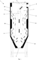
- 1 indicates as a whole an apparatus for processing (in particular, by heating) incoherent material, i.e. in the form of granules and/or micro-granules and/or pellets and/or powder and/or or flakes or similar, in particular hygroscopic incoherent material, with a process gas.
- the hygroscopic incoherent material may include, in particular, incoherent plastics.
- the process gas may comprise, in particular, a heated gas.
- the process gas may include, in particular, air, or an inert gas (for example, nitrogen), or another gas. In this specific example, the process gas is air.
- the apparatus 1 comprises a container 2, in particular a vertically extended container 2.
- the container 2 may include, in particular, a hopper for drying and/or dehumidifying incoherent plastics (polymer granules or pellets).
- the container 2 may comprise, in particular, a vertical central longitudinal axis.
- the apparatus 1 comprises an upper inlet 3 configured for the entry of incoherent material into the container 2.
- the apparatus 1 comprises a lower outlet 4 configured for the exit of incoherent material from the container 2.
- the apparatus 1 comprises at least one first gas port 5 configured to introduce/extract process gas into/from the container 2.
- the apparatus 1 comprises at least one second gas port 6 configured to extract/introduce process gas from/into the container 2.
- the process gas may include, in particular, heated gas (to a controlled temperature value) and/or dehumidified gas (to a controlled dewpoint value).
- the apparatus 1 may comprise, in particular, a closed gas circuit (not shown) configured to withdraw the used process gas (for example, wet process gas) exiting the container 2 (in particular, exiting one of the two gas ports, for example from the second gas port 6), treat (for example, dehumidify) the used process gas and recirculate the treated process gas to reintroduce it into the container 2 (in particular, through the other of the two gas ports, for example through the first gas port 5).
- the apparatus 1 may comprise, in particular (as an alternative or in addition to the closed gas circuit), an open gas circuit (not shown) in which the process gas introduced into the container is not treated process gas coming from an outlet of the container 2 and recirculated, but treated process gas coming, for example, from the external environment.
- the apparatus 1 may comprise, in particular, operating means (not shown) for generating a process gas flow in the (closed or open) gas circuit.
- the operating means may comprise, in particular, a blower (for example a side channel blower), or a fan, or other flow generator.
- the apparatus 1 may comprise, in particular, treatment means (not shown) for treating the process gas to be introduced into the container 2.
- the treatment means may comprise, in particular, dehumidification means for dehumidifying the process gas, for example dehumidification means comprising two dehumidification units arranged in parallel to alternate treatment cycles and regeneration cycles.
- the apparatus 1 may comprise, in particular, regeneration means (not shown) for regenerating the dehumidification means, for example by heating with a regeneration fluid (for example, air heated by at least one heater, in particular an electric resistance heater).
- a regeneration fluid for example, air heated by at least one heater, in particular an electric resistance heater.
- the container 2 internally includes at least one material volume 7 configured to contain the incoherent material.
- the material volume 7 is configured so that the incoherent material can enter the material volume 7 through the upper inlet 3 and can exit the material volume 7 through the lower outlet 4.
- the transport of the incoherent material through the material volume may occur, for example, by descent of the material due to gravity and could be favored by transport promoting means (not shown) comprising, for example, means for stirring the material (for example, a set of rotating blades).
- the container 2 internally includes at least one gas volume separated from the material volume 7.
- the gas volume may comprise, in particular, a volume which is internal to the container, and which is configured to allow the passage of the gas and to avoid the passage of the incoherent material, even if a possible passage (generally unwanted but almost inevitable) of very fine particles (fragments, dust, etc.) present in the incoherent material is possible.
- the gas volume comprises a plurality of portions separated from each other.
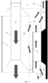
- the plurality of portions of the gas volume comprises at least an inner portion 8, a lower outer portion 9, an intermediate portion 10 and an upper outer portion 11.
- At least a part of the lower outer portion 9 is arranged below the intermediate portion 10 and that at least a part of the upper outer portion 11 is arranged above the intermediate portion 10. It is possible to provide, in particular, that at least a part of the lower outer portion 9 is arranged more externally (with reference to a vertical central axis of the container 2) with respect to the intermediate portion 10 and that at least a part of the upper outer portion 11 is arranged more externally (with reference to a vertical central axis of the container 2) with respect to the intermediate portion 10. It is possible to provide, in particular, that at least a part of the inner portion 8 is arranged more internally (with reference to a vertical central axis of the container 2) with respect to the intermediate portion 10.
- the inner portion 8 may occupy, in particular, at least in part a central area of the container 2. A part of the inner portion 8 is separated from the material volume 7 by a first gas-material interface 12 permeable to the gas.
- the lower outer portion 9 is at least partly annular in shape and is arranged so as to surround a part of the material volume 7.
- the lower outer portion 9 is separated from the material volume 7 by a second gas-material interface 13 permeable to gas.
- the second gas-material interface 13 internally delimits the lower outer portion 9.
- the intermediate portion 10 is at least partly annular in shape and is arranged so as to surround a part of the inner portion 8.
- the intermediate portion 10 is separated from the inner portion 8 by a gas-impermeable wall 14 which internally delimits the intermediate portion 10.
- the wall 14 may comprise, in particular, a portion of duct configured to transport the process gas, and which can contribute to define the inner portion 8 of the gas volume.
- the wall 14 may comprise, in particular, a wall at least partly cylindrical in shape.
- the intermediate portion 10 is separated from the material volume 7 by a third gas-material interface 15 that is permeable to the gas.
- the third gas-material interface 15 externally delimits the intermediate portion 10.
- the upper outer portion 11 is at least partly annular in shape and is arranged so as to surround a part of the material volume 7.
- the upper outer portion 11 is arranged above the lower outer portion 9.
- the upper outer portion 11 is separated from the material volume 7 by a fourth gas-permeable gas-material interface 16.
- the fourth gas-material interface 16 internally delimits the upper outer portion 11.
- the inner portion 8 is configured so that the process gas can pass through the inner portion 8 passing between the first gas port 5 and the first gas-material interface 12 (if the first gas port 5 is the gas inlet into the container 2, then the process gas flow will proceed from the first gas port 5 to the first gas-material interface 12, as indicated by the arrows in the attached figures, with a process gas flow direction predominantly downwards).
- the upper outer portion 11 is configured so that the process gas can pass through the upper outer portion 11 passing between the second gas port 6 and the fourth gas-material interface 16 (if the second gas port 6 is the outlet gas from the container 2, then the process gas flow will proceed from the fourth gas-material interface 16 to the second gas port 6, as indicated by the arrows in the attached figures, with a process gas flow direction predominantly upwards).
- a maximum cross-section width D of the intermediate portion 10 is greater than an average cross-section width of the lower outer portion 9, and it is also possible to provide, in addition or alternatively, that the maximum cross-section width D of the intermediate portion 10 is greater than an average cross-section width of the upper outer portion 11, where cross-section width means a dimension in the horizontal direction of a cross-section of the respective portion of the gas volume.
- the maximum cross-section width D of the intermediate portion 10 is greater than both an average cross-section width of the lower outer portion 9 and an average cross-section width of the upper outer portion 11.
- the maximum cross-section width D of the intermediate portion 10 may be, in particular, greater than a maximum cross-section width E of the lower outer portion 9 and/or it may be, in particular, greater than a maximum width F of cross section of the upper outer portion 11.
- a ratio D/E between the maximum cross-section width D of the intermediate portion 10 and the maximum cross-section width E of the lower outer portion 9 is greater than 6/5, more particular greater than 5/4, or greater than 4/3, or greater than 3/2.
- the D/E ratio may be, as in the specific example illustrated, greater than 3/2, or greater than 8/5, for example included in the range 2.0 ⁇ 0.5, or approximately equal to 2.0.
- a ratio D/F between the maximum cross-section width D of the intermediate portion 10 and the maximum cross-section width F of the upper outer portion is greater than 6/5, more particularly greater than 5/4, or greater than 4/3, or greater than 3/2.
- the D/F ratio may be, as in the specific example illustrated, greater than 3/2, or greater than 8/5, for example included in the interval 2.0 ⁇ 0.5, or approximately equal to 2.0.
- the maximum cross-section width D of the intermediate portion 10 may be, in particular, greater than 10.5 cm and/or less than 19.5 cm and/or included in the range between 10.5 cm and 19.5 cm and/or within the range 15 ⁇ 2.5 cm.
- the maximum cross-section width E of the lower outer portion 9 may be, in particular, greater than 2.5 cm and/or included in the range 7.5 ⁇ 2.5 cm.
- the maximum cross-section width F of the upper outer portion 11 may be, in particular, greater than 3 cm and/or included in the range 7.5 ⁇ 2.5 cm.
- the maximum cross-section width D of the intermediate portion 10 is greater than 10.5 cm
- the maximum cross-section width E of the lower outer portion 9 is greater than 2.5 cm
- the maximum cross-section width F of the upper outer portion 11 is greater than 3 cm.
- the maximum cross-section width D of the intermediate portion 10 is less than 19.5 cm
- the maximum cross-section width E of the lower outer portion 9 is less than 12.7 cm
- the maximum cross-section width F of the upper outer portion 11 is less than 11.9 cm.
- An average cross-sectional width of the intermediate portion 10 may be, in particular, greater than the average cross-sectional width of the lower outer portion 9.
- An average cross-sectional width of the intermediate portion 10 may be, in particular, greater than average cross-sectional width of the upper outer portion 11.
- a lower end portion of the intermediate portion 10 is internally delimited by a gas-impermeable annular wall 17 and flared downwards (i.e. which increases its diameter by proceeding downwards).
- the annular wall 17 may be, in particular, of a truncated cone shape (with a smaller upper base and a greater lower base).
- the annular wall 17 may include, in particular, a portion of the conduit which is configured to transport the process gas and which can contribute to defining the inner portion 8 of the gas volume.
- the annular wall 17 may, in particular, be joined with the wall 14.
- the annular wall 17 may be shaped so that the lower end portion of the intermediate portion 10 has a cross-section width that decreases downwards (see Figure 4 or 5 ). It has been seen that the shape of the annular wall 17 and/or of the lower end portion of the intermediate portion 10 contributes to promoting a certain accumulation of any thinner particles of material, which pass through the third gas-material interface 15, on the bottom of the intermediate portion 10, favoring the flow of the process gas along its path inside the container 2, also reducing the risk that these thinner particles could be transported in flight and reach the gas outlet (i.e. the second gas port 6).
- At least a part of the lower end portion of the intermediate portion 10 is arranged alongside at the same vertical height, for a height H, an upper end portion of the lower outer portion 9.
- a lower end portion of the upper outer portion 11 is delimited externally by an annular wall 18 which is impermeable to gas and flared downwards (i.e. which decreases its diameter by proceeding downwards).
- the annular wall 18 may, in particular, be of a truncated cone shape.
- the annular wall 18 may be shaped so that the lower end portion of the upper outer portion 11 has a cross-sectional width that decreases downwards (see Figure 3 or 4 ). It has been seen that the shape of the annular wall 18 and/or of the lower end portion of the upper outer portion 11 contributes to promoting a certain accumulation of any finer particles of material, which pass through the fourth gas-material interface 16, on the bottom of the upper outer portion 11, favoring the flow of the process gas along its path inside the container 2, also reducing the risk that these thinner particles could be transported in flight and reach the gas outlet (i.e. the second gas port 6).
- a K/J ratio is greater than 1/3, where K is a minimum vertical distance between the second gas-material interface 13 and the fourth gas-material interface 16 and J is a total height of the third gas-material interface 15. It is possible to provide, more specifically, that the K/J ratio is greater than 1/2, or included in an interval 2/3 ⁇ 1/6, or approximately equal to 2/3. In other examples, the K/J ratio may be expected to be within a range of 3/5 ⁇ 1/5, or approximately equal to 3/5. It has been seen that the choice of these K/J ratios improves the efficiency of the thermal process on the incoherent material in container 2, obtaining a valid compromise between the pressure drops in the process gas flow and the transfer of thermal energy from the gas to the material.
- the third gas-material interface 15 may include, in particular, a lower portion placed horizontally alongside, for a section of height H, an upper portion of the second gas-material interface 13. It is possible to provide, in particular, that the height H is less than the minimum vertical distance K between the second gas-material interface 13 and the fourth gas-material interface 16. It is possible to provide, in particular, that the H/K ratio is less than 4/5, or less than 3/4, or less than 2/3, or less than 1/2, or within the range 1/2 ⁇ 1/4. It has been seen that, also in this case, the choice of these H/K ratios improves the performance of the thermal process on the incoherent material in container 2 and reduces the risk of localized overheating.
- the height H of the side-by-side positioning between the intermediate portion 10 and the lower outer portion 9 may be, in particular, greater than 15.5 cm and/or less than 25.3 cm and/or included in the range between 15.5 cm and 25.3 cm and/or within the range of 20.4 ⁇ 3.6 cm.
- the minimum vertical distance K between the second gas-material interface 13 and the fourth gas-material interface 16 may be, in particular, greater than 45 cm and/or less than 72.5 cm and/or included in the range between 45 cm and 72.5 cm and/or within the range 58.5 ⁇ 8.5 cm.
- the total height J of the third gas-material interface 15 may be, in particular, greater than 83 cm and/or less than 117.5 cm and/or included in the range between 83 cm and 117.5 cm and/or included in the range 100 ⁇ 12 cm.
- the first gas-material interface 12 may comprise, in particular, at least one downward frusto-conical portion with a C1 taper, where taper of a frusto-conical portion means, in this description, the ratio between the difference of the diameters of two cross sections of the frusto-conical section and the axial distance between the same cross sections.
- the second gas-material interface 13 may comprise, in particular, at least one downward frusto-conical portion with a C2 taper. It is possible to provide, in particular, that C1 > C2, in particular C1 - C2 > 0.05, more specifically C1 - C2 > 0.10. It has been seen that a certain difference in taper between C1 and C2 improves the homogeneity of the heat transfer from the process gas to the incoherent material.
- the lower outer portion 9 may be, in particular, at least partially externally delimited by a flared wall 19 which is impermeable to gas and which has a shape that flares downwards.
- the flared wall 19 may comprise, in particular, a frusto-conical wall with a C3 taper.
- the flared wall 19 may, in particular, be arranged at the same height level as at least a part of the frusto-conical portion with a conicity C2 of the second gas-material interface 13, in which C3 > C2, in particular C3 - C2 > 0.05, more specifically C3 - C2 > 0.10. It has been seen, also in this case, that a certain difference between the C2 and C3 tapers makes it possible to improve the homogeneity of the heat transfer from the process gas to the incoherent material.
- the taper C1 may be, in particular, greater than 0.85 and/or less than 1.2 and/or included in the range between 0.85 and 1.2 and/or included in the range 1.02 ⁇ 0.15.
- the C2 taper may be, in particular, greater than 0.63.
- 20 indicates a casing (impermeable to gas, for example an insulated casing) which surrounds and encloses the material volume and the gas volume.
- a casing imppermeable to gas, for example an insulated casing
- Each of the gas-material interfaces 12, 13, 15 and 16 may comprise, in particular, a perforated wall.
- the second gas-material interface 13 may comprise, as in the specific illustrated example, a lower part with a flared shape (in particular, frusto-conical) towards the bottom and an upper part with a cylindrical shape. This flared lower part may be joined to the cylindrical upper part.
- the apparatus 1 it is possible to implement a method for processing (in particular, for heating) incoherent material with a process gas.
- the processed incoherent material includes plastics (polymer granules) which is introduced into the material volume 7 through the upper inlet 3 and is extracted from the container 2 through the lower outlet 4.
- the process gas is heated and then introduced into the gas volume through the first gas port 5 (or the second gas port 6, in examples not illustrated) and is extracted from the second gas port 6 (or from the first gas port 5, in examples not illustrated).
- the processed incoherent plastics comprise polyolefins and/or polyethylenes and/or polyamides.
- the processed incoherent plastics may comprise, in particular, at least in part PCR (Post-Consumer Recycled) recycled material, for example with a weight percentage of PCR incoherent plastics between 20% and 100%.
- the processed incoherent plastic material may include, in particular, particles within certain grain size ranges, for example cylindrical granules or pellets with a diameter between 1.5 mm and 4 mm and a length between 2 mm and 6 mm and/or spherical granules or pellets with a diameter between 1.5 mm and 5 mm and/or ellipsoidal granules or pellets with a major diameter between 2.5 mm and 6 mm and a smaller diameter between 1.5 mm and 4 mm and/or flakes with a thickness between 0.1 mm and 1 mm, with a width between 1 mm and 10 mm and with a length between 1 mm and 10 mm.
- particles within certain grain size ranges for example cylindrical granules or pellets with a diameter between 1.5 mm and 4 mm and a length between 2 mm and 6 mm and/or spherical granules or pellets with a diameter between 1.5 mm and 5 mm and/or ellipsoidal gran
- the process gas for example, heated and/or dehumidified air
- the process gas enters the inner portion 8 and descends downwards to then enter the material volume 7 through the first gas-material interface 12.
- a part of the process gas exiting from the first gas-material interface 12 will be able to ascend along the material volume 7 crossing countercurrent the incoherent material that descends towards the lower outlet 4, while another part of the process gas exiting from the first gas-material interface 12 will be able to pass through the incoherent material for a certain distance and then enter the lower outer portion 9 and then exit from the same lower outer portion 9 and return to the material volume 7, always passing through the second gas-material interface 13.
- a part of the process gas that rises along the material volume 7 may enter the intermediate portion 10 and then exit from the same intermediate portion 10 (in particular after having ascended a portion of the intermediate portion 10) and then return to the material volume 7, always passing through the third gas-material interface 15.
Landscapes
- Engineering & Computer Science (AREA)
- Mechanical Engineering (AREA)
- General Engineering & Computer Science (AREA)
- Physics & Mathematics (AREA)
- Thermal Sciences (AREA)
- Life Sciences & Earth Sciences (AREA)
- Microbiology (AREA)
- Devices And Processes Conducted In The Presence Of Fluids And Solid Particles (AREA)
Applications Claiming Priority (1)
| Application Number | Priority Date | Filing Date | Title |
|---|---|---|---|
| IT102023000010956A IT202300010956A1 (it) | 2023-05-30 | 2023-05-30 | Apparato e metodo per processare materiale incoerente |
Publications (1)
| Publication Number | Publication Date |
|---|---|
| EP4470742A1 true EP4470742A1 (de) | 2024-12-04 |
Family
ID=88097975
Family Applications (1)
| Application Number | Title | Priority Date | Filing Date |
|---|---|---|---|
| EP24170413.9A Pending EP4470742A1 (de) | 2023-05-30 | 2024-04-16 | Vorrichtung und verfahren zur verarbeitung inkohärenten materials |
Country Status (2)
| Country | Link |
|---|---|
| EP (1) | EP4470742A1 (de) |
| IT (1) | IT202300010956A1 (de) |
Citations (7)
| Publication number | Priority date | Publication date | Assignee | Title |
|---|---|---|---|---|
| US6405454B1 (en) * | 1998-09-04 | 2002-06-18 | Motan Holding Gmbh | Method and apparatus for heating and/or drying flowable loose material |
| WO2010053090A1 (ja) * | 2008-11-05 | 2010-05-14 | 株式会社松井製作所 | 粉粒体材料の乾燥方法、及び粉粒体材料の乾燥装置 |
| DE102009049275A1 (de) * | 2009-10-13 | 2011-04-14 | Gräff, Roderich W., Dr.-Ing. | Verfahren und Vorrichtung zum Trocknen von Kunststoffgranulaten |
| DE102010024917A1 (de) | 2010-06-18 | 2011-12-22 | Ralf Schneider Holding Gmbh | Vorrichtung zum Trocknen von fließfähigem Schüttgut |
| US8763273B2 (en) * | 2010-08-03 | 2014-07-01 | Moretto S.P.A. | Hopper structure, dehumidification plant and method for dehumidifying granular plastic material |
| US20210387380A1 (en) | 2018-10-24 | 2021-12-16 | Stefan Bock | Method and device for the fast and efficient heating of plastic granulates for preparing for the processing in a plasticization |
| IT202000018232A1 (it) * | 2020-07-28 | 2022-01-28 | Piovan Spa | Apparato e metodo di deodorizzazione |
-
2023
- 2023-05-30 IT IT102023000010956A patent/IT202300010956A1/it unknown
-
2024
- 2024-04-16 EP EP24170413.9A patent/EP4470742A1/de active Pending
Patent Citations (7)
| Publication number | Priority date | Publication date | Assignee | Title |
|---|---|---|---|---|
| US6405454B1 (en) * | 1998-09-04 | 2002-06-18 | Motan Holding Gmbh | Method and apparatus for heating and/or drying flowable loose material |
| WO2010053090A1 (ja) * | 2008-11-05 | 2010-05-14 | 株式会社松井製作所 | 粉粒体材料の乾燥方法、及び粉粒体材料の乾燥装置 |
| DE102009049275A1 (de) * | 2009-10-13 | 2011-04-14 | Gräff, Roderich W., Dr.-Ing. | Verfahren und Vorrichtung zum Trocknen von Kunststoffgranulaten |
| DE102010024917A1 (de) | 2010-06-18 | 2011-12-22 | Ralf Schneider Holding Gmbh | Vorrichtung zum Trocknen von fließfähigem Schüttgut |
| US8763273B2 (en) * | 2010-08-03 | 2014-07-01 | Moretto S.P.A. | Hopper structure, dehumidification plant and method for dehumidifying granular plastic material |
| US20210387380A1 (en) | 2018-10-24 | 2021-12-16 | Stefan Bock | Method and device for the fast and efficient heating of plastic granulates for preparing for the processing in a plasticization |
| IT202000018232A1 (it) * | 2020-07-28 | 2022-01-28 | Piovan Spa | Apparato e metodo di deodorizzazione |
Also Published As
| Publication number | Publication date |
|---|---|
| IT202300010956A1 (it) | 2024-11-30 |
Similar Documents
| Publication | Publication Date | Title |
|---|---|---|
| EP0125516B1 (de) | Vorrichtung zum Granulieren | |
| US5199184A (en) | Fluidized-bed or effervescent bed chamber, treatment tower and process in two stages | |
| US8763273B2 (en) | Hopper structure, dehumidification plant and method for dehumidifying granular plastic material | |
| US5052123A (en) | Drying and heating of polyamide granules | |
| US8142551B2 (en) | Energy recuperating filtration apparatus | |
| US6148540A (en) | Pulverized body drying method and apparatus | |
| FI82980B (fi) | Foerfarande och anordning foer avlaegsnande av vatten fraon partikelformigt material. | |
| CN105043016A (zh) | 用于松散物料的烘干和/或结晶的方法以及用于实施这种方法的设备 | |
| KR20070087076A (ko) | 일련의 원통형 챔버의 회전 유동층 장치 및 방법 | |
| KR102134561B1 (ko) | 펠릿 건조 및 탈기 방법 | |
| US11913721B2 (en) | Apparatus, a bottom plate component and a method for drying bulk particulate material | |
| EP4470742A1 (de) | Vorrichtung und verfahren zur verarbeitung inkohärenten materials | |
| EP3722717B1 (de) | Hopper für thermisches konditionieren von kunststoffe, anlage einschliesslich eines solchen hoppers und verfahren zur verwendung eines solchen hoppers | |
| US3028681A (en) | Apparatus for treating granular materials | |
| US6716959B2 (en) | Device and method for treating plastic material | |
| KR101081354B1 (ko) | 유동층 건조 및 분류장치 | |
| RU2182297C1 (ru) | Сушилка с активной гидродинамикой и пофракционной обработкой материала | |
| EP4286128B1 (de) | Vorrichtung und verfahren zur verarbeitung von material in einem trichter | |
| CN207894121U (zh) | 颗粒物料连续分级筛选气流干燥器 | |
| CN210211161U (zh) | 一种高分子材料注塑装置 | |
| CN101579610A (zh) | 用于松散材料的快速热处理的设备和方法 | |
| JP3126023B2 (ja) | 連続造粒・コーティング装置 | |
| KR20210151920A (ko) | 미립자 재료들을 냉각하기 위한 디바이스 | |
| IT202200026736A1 (it) | Apparato e Metodo di Deumidificazione | |
| RU15007U1 (ru) | Устройство для сушки материалов |
Legal Events
| Date | Code | Title | Description |
|---|---|---|---|
| PUAI | Public reference made under article 153(3) epc to a published international application that has entered the european phase |
Free format text: ORIGINAL CODE: 0009012 |
|
| STAA | Information on the status of an ep patent application or granted ep patent |
Free format text: STATUS: REQUEST FOR EXAMINATION WAS MADE |
|
| 17P | Request for examination filed |
Effective date: 20241017 |
|
| AK | Designated contracting states |
Kind code of ref document: A1 Designated state(s): AL AT BE BG CH CY CZ DE DK EE ES FI FR GB GR HR HU IE IS IT LI LT LU LV MC ME MK MT NL NO PL PT RO RS SE SI SK SM TR |
|
| P01 | Opt-out of the competence of the unified patent court (upc) registered |
Free format text: CASE NUMBER: APP_9952/2025 Effective date: 20250227 |