EP4470709A1 - Laser processing machine, laser processing method, and laser processing program - Google Patents
Laser processing machine, laser processing method, and laser processing program Download PDFInfo
- Publication number
- EP4470709A1 EP4470709A1 EP22924182.3A EP22924182A EP4470709A1 EP 4470709 A1 EP4470709 A1 EP 4470709A1 EP 22924182 A EP22924182 A EP 22924182A EP 4470709 A1 EP4470709 A1 EP 4470709A1
- Authority
- EP
- European Patent Office
- Prior art keywords
- laser beam
- laser processing
- cell
- along
- laser
- Prior art date
- Legal status (The legal status is an assumption and is not a legal conclusion. Google has not performed a legal analysis and makes no representation as to the accuracy of the status listed.)
- Pending
Links
Images







Classifications
-
- B—PERFORMING OPERATIONS; TRANSPORTING
- B23—MACHINE TOOLS; METAL-WORKING NOT OTHERWISE PROVIDED FOR
- B23K—SOLDERING OR UNSOLDERING; WELDING; CLADDING OR PLATING BY SOLDERING OR WELDING; CUTTING BY APPLYING HEAT LOCALLY, e.g. FLAME CUTTING; WORKING BY LASER BEAM
- B23K26/00—Working by laser beam, e.g. welding, cutting or boring
- B23K26/08—Devices involving relative movement between laser beam and workpiece
- B23K26/082—Scanning systems, i.e. devices involving movement of the laser beam relative to the laser head
-
- B—PERFORMING OPERATIONS; TRANSPORTING
- B23—MACHINE TOOLS; METAL-WORKING NOT OTHERWISE PROVIDED FOR
- B23K—SOLDERING OR UNSOLDERING; WELDING; CLADDING OR PLATING BY SOLDERING OR WELDING; CUTTING BY APPLYING HEAT LOCALLY, e.g. FLAME CUTTING; WORKING BY LASER BEAM
- B23K26/00—Working by laser beam, e.g. welding, cutting or boring
- B23K26/14—Working by laser beam, e.g. welding, cutting or boring using a fluid stream, e.g. a jet of gas, in conjunction with the laser beam; Nozzles therefor
-
- B—PERFORMING OPERATIONS; TRANSPORTING
- B23—MACHINE TOOLS; METAL-WORKING NOT OTHERWISE PROVIDED FOR
- B23K—SOLDERING OR UNSOLDERING; WELDING; CLADDING OR PLATING BY SOLDERING OR WELDING; CUTTING BY APPLYING HEAT LOCALLY, e.g. FLAME CUTTING; WORKING BY LASER BEAM
- B23K26/00—Working by laser beam, e.g. welding, cutting or boring
- B23K26/352—Working by laser beam, e.g. welding, cutting or boring for surface treatment
- B23K26/355—Texturing
-
- B—PERFORMING OPERATIONS; TRANSPORTING
- B23—MACHINE TOOLS; METAL-WORKING NOT OTHERWISE PROVIDED FOR
- B23K—SOLDERING OR UNSOLDERING; WELDING; CLADDING OR PLATING BY SOLDERING OR WELDING; CUTTING BY APPLYING HEAT LOCALLY, e.g. FLAME CUTTING; WORKING BY LASER BEAM
- B23K26/00—Working by laser beam, e.g. welding, cutting or boring
- B23K26/36—Removing material
- B23K26/362—Laser etching
Definitions
- the present invention relates to a laser processing machine, a laser processing method, and a laser processing program.
- a known laser marking device is provided with a laser light source that emits a laser beam, marking sequence control means to output marking data for marking each first cell in the workpiece according to a sequence based on vertical and horizontal numberings of the matrix corresponding to each first cell, and a galvano scanner that sequentially receives the marking data and sequentially marks each first cell in the surface of the workpiece (Patent Literature 1 and the like).
- the marking sequence control means when a plurality of the first cells are adjacent to each other either vertically or horizontally in the matrix, the marking sequence control means outputs the marking data of the first cells in a sequence that does not mark the adjacent first cells consecutively.
- Patent Literature 1 JP 2001-232848 A
- the laser marking device of Patent Literature 1 has a problem in that when marking a cell that is larger than an irradiation diameter of the laser beam, for example, the first cell is marked by radiating the laser beam while meandering in a spiral pattern inside the first cell, and thus the marking of each first cell takes a long time.
- One aspect of the present invention is a laser processing machine, a laser processing method, and a laser processing program capable of engraving a two-dimensional code with high reading accuracy in a short time.
- a laser processing machine is a laser processing machine configured to engrave, in a surface of a workpiece, a matrix-type two-dimensional code in which a first cell as a unit irradiation area and a second cell as a unit non-irradiation area are arranged in a desired array pattern in a first direction and a second direction orthogonal to the first direction, the laser processing machine being provided with a laser processing head configured to irradiate the workpiece with a laser beam, a moving mechanism configured to move the laser beam radiated from the laser processing head in the first direction and the second direction, and a control unit configured to control the moving mechanism, wherein the laser processing machine is configured to irradiate each first cell with the laser beam along both the first direction and the second direction.
- a laser processing method is a laser processing method for engraving, in a surface of a workpiece, a matrix-type two-dimensional code in which a first cell as a unit irradiation area and a second cell as a unit non-irradiation area are arranged in a desired array pattern in a first direction and a second direction orthogonal to the first direction, wherein each first cell is irradiated with a laser beam along both the first direction and the second direction.
- a laser processing program is a laser processing program for engraving, in a surface of a workpiece, a matrix-type two-dimensional code in which a first cell as a unit irradiation area and a second cell as a unit non-irradiation area are arranged in a desired array pattern in a first direction and a second direction orthogonal to the first direction, the laser processing program causing a control unit to execute an engraving process for irradiating each first cell with a laser beam along both the first direction and the second direction.
- the first cell is irradiated with the laser beam along both the first direction and the second direction, whereby a two-dimensional code with high reading accuracy can be engraved in a short time.
- a two-dimensional code with high reading accuracy can be engraved in a short time.
- Figure 1 is a schematic diagram illustrating a laser processing machine according to the embodiment of the present invention.
- the laser processing machine 1 is a laser processing machine that engraves, in a surface of a workpiece W, a matrix-type two-dimensional code in which a first cell as a unit irradiation area and a second cell as a unit non-irradiation area are arranged in a desired array pattern in a first direction and a second direction orthogonal to the first direction.
- the first direction is a Y-axis direction in Figure 1 and the second direction is an X-axis direction in Figure 1 , but the directions are not limited thereto.
- a matrix-type two-dimensional code is a two-dimensional code having an array pattern of n rows and m columns (where n and m are integers equal to or greater than 2) in which square first and second cells are plurally arranged in a freely chosen array.
- a matrix-type two-dimensional is a square or rectangular two-dimensional code such as a QR Code ® or a Data Matrix.
- the laser processing machine 1 includes a laser processing head 30 that irradiates a workpiece W with a laser beam L and a moving mechanism 20 that moves the laser beam L radiated from the laser processing head 30 in a first direction and a second direction, in which each first cell is irradiated with the laser beam L along both the first direction and the second direction.
- the laser processing machine 1 also includes a laser oscillator 10 that generates and emits the laser beam L, a process fiber 12 that conveys the laser beam L emitted by the laser oscillator 10 to the laser processing head 30, a processing table 21 on which the workpiece W is mounted, a control device 50, and an assist gas supply device (not illustrated).
- the laser oscillator 10 generates the laser beam L, and supplies the laser beam L to the laser processing head 30 via the process fiber 12.
- the laser oscillator suitably used as the laser oscillator 10 is, for example, a type in which a seed light emitted by a laser diode excites and amplifies Yb or the like in a resonator to emit the laser beam L at a predetermined wavelength, or a type that directly uses the laser beam L emitted by a laser diode.
- Examples of the laser oscillator 10 as a solid-state laser oscillator include a fiber laser oscillator, a YAG laser oscillator, a disk laser oscillator, a DDL oscillator, and the like.
- the laser oscillator 10 emits the laser beam L in a 1 ⁇ m band with a wavelength of 900 nm to 1100 nm.
- the DDL oscillator emits the laser beam L with a wavelength of 910 nm to 950 nm
- the fiber laser oscillator emits the laser beam L with a wavelength of 1060 nm to 1080 nm.
- the moving mechanism 20 is configured to drive at least one of the laser processing head 30 or the processing table 21 so that the laser processing head 30 and the processing table 21 move relative to one another.
- the moving mechanism 20 includes an X-axis carriage 22 and a Y-axis carriage 23.
- the X-axis carriage 22 is configured in a gate type, is disposed straddling the processing table 21, and is configured to be freely movable over the processing table 21 in the X-axis direction.
- the Y-axis carriage 23 is attached to the X-axis carriage 22 and is configured to be freely movable in the Y-axis direction perpendicular to the X-axis direction.
- the laser processing head 30 is attached to an end of the Y-axis carriage 23.
- the moving mechanism 20 is configured to move the laser processing head 30 in the X-axis direction, the Y-axis direction, or any combined direction of the X and Y axes, along the surface of the workpiece W mounted on the processing table 21.
- the moving mechanism 20 may also be configured such that a position of the laser processing head 30 is fixed and the workpiece W is moved relative to the laser processing head 30.
- Figure 2 is a schematic diagram illustrating the laser processing head of the present embodiment.
- the laser processing head 30 irradiates the workpiece W on the processing table 21 with the laser beam L conveyed from the laser oscillator 10 via the process fiber 12.
- the laser processing head 30 includes a housing 30a including an irradiation center axis of the laser beam L, and inside this housing 30a, the laser processing head 30 includes a collimating lens 31 entered by the laser beam L emitted from the emitting end of the process fiber 12, a galvano scanner unit 32 that functions as a beam vibrating mechanism, and a bend mirror 35 by which the laser beam L emitted from the galvano scanner unit 32 is reflected downward in a Z-axis direction perpendicular to the X and Y axes.
- the laser processing head 30 also includes a condensing lens 36 that focuses the laser beam L reflected by the bend mirror 35
- a tip portion of the housing 30a is provided with a nozzle 30b having a circular aperture for irradiating the workpiece W with the laser beam L.
- This nozzle 30b has a nozzle function for directing a flow of gas supplied from the assist gas supply device to the workpiece W coaxially with the laser beam L in order to remove the molten workpiece W, and is detachably provided on the housing 30a.
- the condensing lens 36 is configured to move freely in directions approaching the workpiece W and going away from the workpiece W by means of a drive section and a moving mechanism not illustrated, in order to adjust a focal position of the laser beam L.
- the galvano scanner unit 32 includes a first scanning section 33 and a second scanning section 34, and is configured to vibrate the laser beam L.
- the first scanning section 33 includes a first scanning mirror 33a to reflect the laser beam L emitted by the collimating lens 31 and a first drive section 33b to rotate the first scanning mirror 33a to be at a predetermined angle.
- the second scanning section 34 includes a second scanning mirror 34a to reflect the laser beam L emitted from the first scanning mirror 33a and a second drive section 34b to rotate the second scanning mirror 34a to be at a predetermined angle.
- the first drive section 33b and the second drive section 34b can reciprocally vibrate the first scanning mirror 33a and the second scanning mirror 34a in a predetermined angular range, respectively, on the basis of control by the control device 50.
- the galvano scanner unit 32 can vibrate the laser beam L radiated from the laser processing head 30 to the workpiece W by reciprocally vibrating one or both of the first scanning mirror 33a and the second scanning mirror 34a.
- the galvano scanner unit 32 may vibrate the laser beam L in a direction orthogonal to the movement direction of the laser beam L, and may also vibrate the laser beam L in the movement direction of the laser beam L and the direction orthogonal to the movement direction of the laser beam L.
- the galvano scanner unit 32 is an example of a beam vibrating mechanism, and the beam vibrating mechanism is not limited to the galvano scanner unit 32 that includes the first scanning section 33 and the second scanning section 34.
- Figure 3 is a functional block diagram schematically illustrating a control device of the present embodiment.
- the control device 50 is an example of a control device that controls each section of the laser processing machine 1. As illustrated in Figure 3 , the control device 50 includes an input unit 51, a display unit 52, a control unit 53, and a storage unit 54.
- the input unit 51 is formed by an input device such as a keyboard, a mouse, a push-button/switch, or the like. By operating the input unit 51, in addition to functions for inputting information normally required in the laser processing machine 1, it is possible to perform operations such as selecting a laser processing program described later in the storage unit 54, for example.
- the display unit 52 includes a display as a display device, and in addition to the functions of a display screen normally required in the laser processing machine 1, displays a selection screen for selecting a laser processing program, for example.
- the display unit 52 may also be configured as a touch panel that includes the functions of the input unit 51. In the case where the display unit 52 is configured as the touch panel, the user can input various information, such as the selection of a laser processing program, to the control device 50 by operating the display unit 52, for example.
- control unit 53 controls the moving mechanism 20 such that the first cells arranged in either the same row or column are each irradiated with the laser beam L consecutively along the first direction, and then the first cells arranged in the other of either the same row or column are each irradiated with the laser beam L consecutively along the second direction.
- the storage unit 54 includes a storage medium such as RAM, ROM, an HDD, or an SSD, and stores various data in a readable and writable way.
- the storage unit 54 stores programs required for control of each unit of the control device 50.
- the storage unit 54 also stores a laser processing program for causing the control unit 53 to execute control of the laser processing machine 1.
- the laser processing program is configured to cause the control unit 53 to perform an engraving process of irradiating each of the first cells with the laser beam L along both the first direction and the second direction.
- the laser processing program is configured to cause the control unit 53 to execute a two-time processing process of irradiating the first cells with the laser beam L along the first direction and then irradiating the first cells with the laser beam L again along the second direction.
- the laser processing machine 1 provided with the above configuration can use the moving mechanism 20 to move the laser processing head 30 relative to the workpiece W and use the galvano scanner unit 32 (beam vibrating mechanism) of the laser processing head 30 to vibrate the laser beam L with which the workpiece W is irradiated, and thereby engrave a highly distinctive matrix-type two-dimensional code on the workpiece W in a short time.
- the laser processing method according to the present embodiment is a laser processing method that irradiates each of the first cells with the laser beam L along both the first direction and the second direction.
- the laser processing method according to the present embodiment irradiates the first cells with the laser beam L along the first direction and then irradiates the first cells with the laser beam L again along the second direction.
- the laser processing machine 1 according to the present embodiment is also capable of engraving a matrix-type two-dimensional code according to a method other than first through fourth laser processing methods indicated below.
- the control unit 53 of the control device 50 controls the moving mechanism 20 to: irradiate, with the laser beam L, first cells in a j-th column (where j is an integer equal to or greater than 1 and less than m) along a first forward direction, and then irradiate, with the laser beam L, first cells in a column other than the j-th column along a first reverse direction; and irradiate, with the laser beam L, first cells in an i-th row (where i is an integer equal to or greater than 1 and less than n) along a second reverse direction, and then irradiate, with the laser beam L, first cells in a row other than the i-th row along a second forward direction.
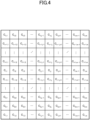
- Figure 4 is a diagram illustrating areas of a matrix-type two-dimensional code of the present embodiment.
- Figure 5 is a diagram illustrating a first processing method by the laser processing machine of the present embodiment. Arrows in Figure 5 indicate the movement directions of the laser processing head 30 (laser beam L).
- Figure 6 is a diagram illustrating the first processing method by a laser processing machine of the present embodiment. Arrows in Figure 6 indicate the movement directions of the laser processing head 30 (laser beam L).
- the laser processing machine 1 irradiates, with the laser beam L, the first cell from the second reverse and forward directions in order starting from the row containing the cell that the laser processing head 30 (laser beam L) last passed.
- the laser processing machine 1 uses the moving mechanism 20 to move the laser processing head 30 from cell C n,m to cell C n,1 in the n-th row along the second reverse direction, and irradiates each first cell in the n-th row with the laser beam L.
- the laser processing machine 1 uses the moving mechanism 20 to move the laser processing head 30 from cell C n-1,1 to cell C n-1,m in the (n-1)-th row along the second forward direction, and irradiates each first cell in the second row with the laser beam L.
- a matrix-type two-dimensional code is engraved in the workpiece W by similarly repeating the above to the first row.
- the laser processing machine 1 uses the moving mechanism 20 to move the laser processing head 30 from cell C 1,m to cell C 1,1 in the first row along the second reverse direction, and irradiates each first cell in the first row with the laser beam L.
- the laser processing machine 1 uses the moving mechanism 20 to move the laser processing head 30 from cell C 2,1 to cell C 2,m in the second row along the second forward direction, and irradiates each first cell in the second row with the laser beam L.
- a matrix-type two-dimensional code is engraved in the workpiece W by similarly repeating the above to the n-th row. According to the above steps, the first laser processing method by the laser processing machine 1 according to the present embodiment is performed.
- the control unit 53 of the control device 50 controls the moving mechanism 20 to: irradiate, with the laser beam L, first cells in the j-th column along the first forward direction, and then irradiate, with the laser beam L, first cells in a column other than the j-th column along the first forward direction; and irradiate, with the laser beam L, first cells in the i-th row along the second reverse direction, and then irradiate, with the laser beam L, first cells in a row other than the i-th row along the second reverse direction.
- Figure 7 is a diagram illustrating the second processing method by the laser processing machine of the present embodiment. Arrows in Figure 7 indicate the movement directions of the laser processing head 30 (laser beam L).
- the laser processing machine 1 irradiates the first cells with the laser beam L from the second direction. Specifically, the laser processing machine 1 uses the moving mechanism 20 to move the laser processing head 30 from cell C n,m to cell C n,1 in the n-th row along the second reverse direction, and irradiates each first cell in the n-th row with the laser beam L. Next, the laser processing machine 1 uses the moving mechanism 20 to move the laser processing head 30 from cell C n-1,m to cell C n-1,1 in the (n-1)-th row along the second reverse direction, and irradiates each first cell in the (n-1)-th row with the laser beam L. A matrix-type two-dimensional code is engraved in the workpiece W by similarly repeating the above to the first row. According to the above steps, the second laser processing method by the laser processing machine 1 according to the present embodiment is performed.
- the third processing method and the fourth processing method are laser processing methods that irradiate first cells with the laser beam L in alternation from the first direction and the second direction.
- the control unit 53 of the control device 50 controls the moving mechanism 20 to, for example: irradiate, with the laser beam L, first cells in the j-th column along the first direction, and then irradiate, with the laser beam L, first cells in the i-th row along the second direction; and irradiate, with the laser beam L, first cells in a column other than the j-th column along the first direction, and then irradiate, with the laser beam L, first cells in a row other than the i-th row along the second direction.
- the third processing method and the fourth processing method will be described in detail.
- the control unit 53 of the control device 50 controls the moving mechanism 20 to: irradiate, with the laser beam L, first cells in the j-th column along the first forward direction, and then irradiate, with the laser beam L, first cells in the (i+1)-th row along the second forward direction; and irradiate, with the laser beam L, first cells in the (j+1)-th column along the first forward direction, and then irradiate, with the laser beam L, first cells in the i-th row along the second forward direction.
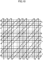
- Figure 10 is a diagram illustrating the third processing method by the laser processing machine of the present embodiment. Arrows in Figure 10 indicate the movement directions of the laser processing head 30 (laser beam L).
- the laser processing machine 1 irradiates the first cells with the laser beam L from the first direction. Specifically, the laser processing machine 1 uses the moving mechanism 20 to move the laser processing head 30 from cell C 1,1 to cell C n,1 in the first column along the first forward direction, and irradiates each first cell in the first column with the laser beam L. Next, the laser processing machine 1 irradiates the first cells with the laser beam L from the second direction. Specifically, the laser processing machine 1 uses the moving mechanism 20 to move the laser processing head 30 from cell C n,1 to cell C n,m in the n-th row along the second forward direction, and irradiates each first cell in the n-th row with the laser beam L.
- the laser processing machine 1 uses the moving mechanism 20 to move the laser processing head 30 from cell C 1,2 to cell C n,2 in the second column along the first forward direction, and irradiates each first cell in the second column with the laser beam L. Thereafter, the laser processing machine 1 uses the moving mechanism 20 to move the laser processing head 30 from cell C n-1,1 to cell C n-1,m in the (n-1)-th row along the second forward direction, and irradiates each first cell in the (n-1)-th row with the laser beam L.
- each first cell in the j-th column is irradiated with the laser beam L along the first forward direction
- each first cell in the (i+1)-th row is irradiated with the laser beam L along the second forward direction.
- each first cell in the (j+1)-th column is irradiated with the laser beam L along the first forward direction
- each first cell in the i-th row is irradiated with the laser beam L along the second forward direction.
- each first cell in the (j+1)-th column is irradiated with the laser beam L along the first forward direction and so on, and each first cell in all rows and columns is irradiated with the laser beam L, thereby engraving a matrix-type two-dimensional code in the workpiece W.
- the third laser processing method by the laser processing machine 1 according to the present embodiment is performed.
- the laser processing machine 1 uses the moving mechanism 20 to move the laser processing head 30 from cell C 1,1 to cell C n,1 in the first column along the first forward direction, and irradiates each first cell in the first column with the laser beam L.
- the laser processing machine 1 uses the moving mechanism 20 to move the laser processing head 30 from cell C 1,1 to cell C 1,m in the first row along the second forward direction, and irradiates each first cell in the first row with the laser beam L.
- the laser processing machine 1 uses the moving mechanism 20 to move the laser processing head 30 from cell C 1,2 to cell C n,2 in the second column along the first forward direction, and irradiates each first cell in the second column with the laser beam L. Thereafter, the laser processing machine 1 uses the moving mechanism 20 to move the laser processing head 30 from cell C 2,1 to cell C 2,m in the second row along the second forward direction, and irradiates each first cell in the second row with the laser beam L.
- the third laser processing method may also be the following example.
- the laser processing machine 1 uses the moving mechanism 20 to move the laser processing head 30 from cell C 1,1 to cell C n,1 in the first column along the first forward direction, and irradiates each first cell in the first column with the laser beam L.
- the laser processing machine 1 uses the moving mechanism 20 to move the laser processing head 30 from cell C n,1 to cell C n,m in the n-th row along the second forward direction, and irradiates each first cell in the n-th row with the laser beam L.
- the laser processing machine 1 uses the moving mechanism 20 to move the laser processing head 30 from cell C 1,m to cell C n,m in the m-th column along the first forward direction, and irradiates each first cell in the m-th column with the laser beam L. Thereafter, the laser processing machine 1 uses the moving mechanism 20 to move the laser processing head 30 from cell C n-1,1 to cell C n-1,m in the (n-1) -th row along the second forward direction, and irradiates each first cell in the (n-1)-th row with the laser beam L.
- the control unit 53 of the control device 50 controls the moving mechanism 20 to: irradiate, with the laser beam L, first cells in the j-th column along the first forward direction, and then irradiate, with the laser beam L, first cells in the (i+1)-th row along the second forward direction; and irradiate, with the laser beam L, first cells in the (j+1)-th column along the first reverse direction, and then irradiate, with the laser beam L, first cells in the i-th row along the second reverse direction.
- Figure 11 is a diagram illustrating the fourth processing method by the laser processing machine of the present embodiment. Arrows in Figure 11 indicate the movement directions of the laser processing head 30 (laser beam L).
- the laser processing machine 1 uses the moving mechanism 20 to move the laser processing head 30 from cell C n,2 to cell C 1,2 in the second column along the first reverse direction, and irradiates each first cell in the second column with the laser beam L. Thereafter, the laser processing machine 1 uses the moving mechanism 20 to move the laser processing head 30 from cell C n-1,m to cell C n-1,1 in the (n-1)-th row along the second reverse direction, and irradiates each first cell in the (n-1)-th row with the laser beam L.
- each first cell in the (j-1)-th column is irradiated with the laser beam L along the first forward direction
- each first cell in the i-th row is irradiated with the laser beam L along the second forward direction.
- each first cell in the j-th column is irradiated with the laser beam L along the first reverse direction
- each first cell in the (i-1)-th row is irradiated with the laser beam L along the second reverse direction.
- each first cell in the (j+1)-th column is irradiated with the laser beam L along the first forward direction and so on, and each first cell in all rows and columns is irradiated with the laser beam L, thereby engraving a matrix-type two-dimensional code in the workpiece W.
- the fourth laser processing method by the laser processing machine 1 according to the present embodiment is performed.
- the laser processing machine 1 uses the moving mechanism 20 to move the laser processing head 30 from cell C 1,1 to cell C n,1 in the first column along the first forward direction, and irradiates each first cell in the first column with the laser beam L.
- the laser processing machine 1 uses the moving mechanism 20 to move the laser processing head 30 from cell C n,1 to cell C n,m in the n-th row along the second forward direction, and irradiates each first cell in the n-th row with the laser beam L.
- the laser processing machine 1 uses the moving mechanism 20 to move the laser processing head 30 from cell C n,m-1 to cell C 1,m-1 in the (m-1)-th column along the first reverse direction, and irradiates each first cell in the (m-1)-th column with the laser beam L. Thereafter, the laser processing machine 1 uses the moving mechanism 20 to move the laser processing head 30 from cell C 2,m to cell C 2,1 in the second row along the second reverse direction, and irradiates each first cell in the second row with the laser beam L.
- the fourth laser processing method may also be the following example.
- the laser processing machine 1 uses the moving mechanism 20 to move the laser processing head 30 from cell C 1,1 to cell C n,1 in the first column along the first forward direction, and irradiates each first cell in the first column with the laser beam L.
- the laser processing machine 1 uses the moving mechanism 20 to move the laser processing head 30 from cell C n-1,1 to cell C n-1,m in the (n-1)-th row along the second forward direction, and irradiates each first cell in the (n-1)-th row with the laser beam L.
- the laser processing machine 1 uses the moving mechanism 20 to move the laser processing head 30 from cell C n,m-1 to cell C 1,m-1 in the (m-1)-th column along the first reverse direction, and irradiates each first cell in the (m-1)-th column with the laser beam L. Thereafter, the laser processing machine 1 uses the moving mechanism 20 to move the laser processing head 30 from cell C 1,m to cell C 1,1 in the first row along the second reverse direction, and irradiates each first cell in the first row with the laser beam L.
- the laser processing machine 1 is a laser processing machine that engraves, in a surface of a workpiece W, a matrix-type two-dimensional code in which a first cell as a unit irradiation area and a second cell as a unit non-irradiation area are arranged in a desired array pattern in a first direction and a second direction orthogonal to the first direction, the laser processing machine being provided with a laser processing head 30 that irradiates the workpiece W with a laser beam L, a moving mechanism 20 that moves the laser beam L radiated from the laser processing head 30 in the first direction and the second direction, and a control unit 53 that controls the moving mechanism 20, wherein each first cell is irradiated with the laser beam L along both the first direction and the second direction.
- the laser processing machine 1 has the advantage that the first cell is irradiated with the laser beam L along both the first direction and the second direction, whereby a two-dimensional code with high reading accuracy can be engraved in a short time.
- the matrix-type two-dimensional code has an array pattern of n rows and m columns (where n and m are integers equal to or greater than 2)
- the control unit 53 controls the moving mechanism 20 to: irradiate, with the laser beam L, first cells in a j-th column (where j is an integer equal to or greater than 1 and less than m) along a first forward direction, and then irradiate, with the laser beam L, first cells in a column other than the j-th column along a first reverse direction; and irradiate, with the laser beam L, first cells in an i-th row (where i is an integer equal to or greater than 1 and less than n) along a second reverse direction, and then irradiate, with the laser beam L, first cells in a row other than the i-th row along a second forward direction.
- Providing such a configuration has the advantage that the laser processing head 30 moves by turning back over rows or columns, whereby
- the matrix-type two-dimensional code has an array pattern of n rows and m columns (where n and m are integers equal to or greater than 2)
- the control unit 53 controls the moving mechanism 20 to: irradiate, with the laser beam L, first cells in a j-th column (where j is an integer equal to or greater than 1 and less than m) along a first forward direction, and then irradiate, with the laser beam L, first cells in a column other than the j-th column along the first forward direction; and irradiate, with the laser beam L, first cells in an i-th row (where i is an integer equal to or greater than 1 and less than n) along a second reverse direction, and then irradiate, with the laser beam L, first cells in a row other than the i-th row along the second reverse direction.
- the matrix-type two-dimensional code has an array pattern of n rows and m columns (where n and m are integers equal to or greater than 2)
- the control unit 53 controls the moving mechanism 20 to: irradiate, with the laser beam L, first cells in a j-th column (where j is an integer equal to or greater than 1 and less than m) along a first direction, and then irradiate, with the laser beam L, first cells in an i-th row (where i is an integer equal to or greater than 1 and less than n) along a second direction; and irradiate, with the laser beam L, first cells in a column other than the j-th column along the first direction, and then irradiate, with the laser beam L, first cells in a row other than the i-th row along the second direction.
- the matrix-type two-dimensional code has an array pattern of n rows and m columns (where n and m are integers equal to or greater than 2)
- the control unit 53 controls the moving mechanism 20 to: irradiate, with the laser beam L, first cells in a j-th column (where j is an integer equal to or greater than 1 and less than m) along a first forward direction, and then irradiate, with the laser beam L, first cells in an (i+1)-th row (where i is an integer equal to or greater than 1 and less than n) along a second forward direction; and irradiate, with the laser beam L, first cells in the (j+1)-th column along the first forward direction, and then irradiate, with the laser beam L, first cells in the i-th row along the second forward direction.
- Providing such a configuration has the advantage that a total distance moved by the laser processing head 30 is shortened and all first cells are irradiated with the laser beam L from the same directions, whereby uneven brightness of reflected light in each of the first cells can be suppressed while shortening the processing time.
- the laser processing machine 1 is provided with a beam vibrating mechanism (galvano scanner unit 32), wherein the beam vibrating mechanism (galvano scanner unit 32) is configured to vibrate the laser beam L, and the control unit 53 uses the moving mechanism 20 to move the laser beam L along one of either the first direction or the second direction while using the beam vibrating mechanism (galvano scanner unit 32) to vibrate the laser beam L along the other of either the first direction or the second direction.
- a beam vibrating mechanism galvano scanner unit 32
- the control unit 53 uses the moving mechanism 20 to move the laser beam L along one of either the first direction or the second direction while using the beam vibrating mechanism (galvano scanner unit 32) to vibrate the laser beam L along the other of either the first direction or the second direction.
- the beam vibrating mechanism (galvano scanner unit 32) vibrates the laser beam L in a direction orthogonal to the movement direction of the laser beam L.
- the beam vibrating mechanism (galvano scanner unit 32) vibrates the laser beam L in the movement direction of the laser beam L and the direction orthogonal to the movement direction of the laser beam L.
- control unit 53 is described as controlling the moving mechanism 20 such that the first cells arranged in either the same row or column are each irradiated with the laser beam L consecutively along the first direction, and then the first cells arranged in the other of either the same row or column are each irradiated with the laser beam L consecutively along the second direction, but is not limited thereto.
- the control unit 53 may also not control the moving mechanism 20 for every first cell such that the first cell is irradiated with the laser beam L along the first direction and then irradiated with the laser beam L again along the second direction.
- control unit 53 is described as controlling the moving mechanism 20 to irradiate first cells with the laser beam L according to the first through fourth laser processing methods, but is not limited thereto, and may also control the moving mechanism 20 to irradiate first cells with the laser beam L according to laser processing methods other than the first through fourth laser processing methods.
- Laser processing methods other than the first through fourth laser processing methods include following first through fourth modifications, for example.
- control unit 53 of the control device 50 controls the moving mechanism 20 to: irradiate, with the laser beam L, first cells in the j-th column along the first forward direction, and then irradiate, with the laser beam L, first cells in a column other than the j-th column along the first reverse direction; and irradiate, with the laser beam L, first cells in the i-th row along the second forward direction, and then irradiate, with the laser beam L, first cells in a row other than the i-th row along the second reverse direction.
- the laser processing machine 1 irradiates the first cells with the laser beam L from the first direction. Specifically, the laser processing machine 1 uses the moving mechanism 20 to move the laser processing head 30 from cell C 1,1 to cell C n,1 in the first column along the first forward direction, and irradiates each first cell in the first column with the laser beam L. Next, the laser processing machine 1 uses the moving mechanism 20 to move the laser processing head 30 from cell C n,2 to cell C 1,2 in the second column along the first reverse direction, and irradiates each first cell in the second column with the laser beam L. The above is repeated similarly to the m-th column.
- Figure 12 is a diagram illustrating the first modification of the laser processing method by the laser processing machine of the present embodiment. Arrows in Figure 12 indicate the movement directions of the laser processing head 30 (laser beam L).
- the laser processing machine 1 irradiates the first cells with the laser beam L from the second direction. Specifically, the laser processing machine 1 uses the moving mechanism 20 to move the laser processing head 30 from cell C 1,1 to cell C 1,m in the first row along the second forward direction, and irradiates each first cell in the first row with the laser beam L. Next, the laser processing machine 1 uses the moving mechanism 20 to move the laser processing head 30 from cell C 2,m to cell C 2,1 in the second row along the second reverse direction, and irradiates each first cell in the second row with the laser beam L. A matrix-type two-dimensional code is engraved in the workpiece W by similarly repeating the above to the n-th row. According to the above steps, the first modification of the laser processing method by the laser processing machine 1 according to the present embodiment is performed.
- control unit 53 of the control device 50 controls the moving mechanism 20 to: irradiate, with the laser beam L, first cells in the j-th column along the first forward direction, and then irradiate, with the laser beam L, first cells in a column other than the j-th column along the first reverse direction; and irradiate, with the laser beam L, first cells in the i-th row along the second forward direction in order starting from the row containing the cell that the laser processing head 30 (laser beam L) last passed, and then irradiate, with the laser beam L, first cells in a row other than the i-th row along the second reverse direction.
- the laser processing machine 1 irradiates the first cells with the laser beam L from the first direction. Specifically, the laser processing machine 1 uses the moving mechanism 20 to move the laser processing head 30 from cell C 1,1 to cell C n,1 in the first column along the first forward direction, and irradiates each first cell in the first column with the laser beam L. Next, the laser processing machine 1 uses the moving mechanism 20 to move the laser processing head 30 from cell C n,2 to cell C 1,2 in the second column along the first reverse direction, and irradiates each first cell in the second column with the laser beam L. The above is repeated similarly to the m-th column.
- the laser processing machine 1 uses the moving mechanism 20 to move the laser processing head 30 from cell C n,1 to cell C n,m in the n-th row along the second forward direction, and irradiates each first cell in the n-th row with the laser beam L.
- the laser processing machine 1 uses the moving mechanism 20 to move the laser processing head 30 from cell C n-1,m to cell C n-1,1 in the (n-1)-th row along the second reverse direction, and irradiates each first cell in the (n-1)-th row with the laser beam L.
- a matrix-type two-dimensional code is engraved in the workpiece W by similarly repeating the above to the first row.
- the laser processing machine 1 uses the moving mechanism 20 to move the laser processing head 30 from cell C 1,1 to cell C 1,m in the first row along the second forward direction, and irradiates each first cell in the first row with the laser beam L.
- the laser processing machine 1 uses the moving mechanism 20 to move the laser processing head 30 from cell C 2,m to cell C 2,1 in the second row along the second reverse direction, and irradiates each first cell in the second row with the laser beam L.
- a matrix-type two-dimensional code is engraved in the workpiece W by similarly repeating the above to the n-th row. According to the above steps, the second modification of the laser processing method by the laser processing machine 1 according to the present embodiment is performed.
- control unit 53 of the control device 50 controls the moving mechanism 20 to: irradiate, with the laser beam L, first cells in the j-th column along the first forward direction, and then irradiate, with the laser beam L, first cells in a column other than the j-th column along the first forward direction; and irradiate, with the laser beam L, first cells in the i-th row along the second forward direction, and then irradiate, with the laser beam L, first cells in a row other than the i-th row along the second forward direction.
- the laser processing machine 1 irradiates the first cells with the laser beam L from the first direction. Specifically, the laser processing machine 1 uses the moving mechanism 20 to move the laser processing head 30 from cell C 1,1 to cell C n,1 in the first column along the first forward direction, and irradiates each first cell in the first column with the laser beam L. Next, the laser processing machine 1 uses the moving mechanism 20 to move the laser processing head 30 from cell C 1,2 to cell C n,2 in the second column along the first forward direction, and irradiates each first cell in the second column with the laser beam L. The above is repeated similarly to the m-th column.
- Figure 13 is a diagram illustrating the third modification of the laser processing method by the laser processing machine of the present embodiment. Arrows in Figure 13 indicate the movement directions of the laser processing head 30 (laser beam L).
- the laser processing machine 1 irradiates the first cells with the laser beam L from the second direction. Specifically, the laser processing machine 1 uses the moving mechanism 20 to move the laser processing head 30 from cell C 1,1 to cell C 1,m in the first row along the second forward direction, and irradiates each first cell in the first row with the laser beam L. Next, the laser processing machine 1 uses the moving mechanism 20 to move the laser processing head 30 from cell C 2,1 to cell C 2,m in the second row along the second forward direction, and irradiates each first cell in the second row with the laser beam L. A matrix-type two-dimensional code is engraved in the workpiece W by similarly repeating the above to the n-th row. According to the above steps, the third modification of the laser processing method by the laser processing machine 1 according to the present embodiment is performed.
- the laser processing machine 1 irradiates the first cells with the laser beam L from the first direction. Specifically, the laser processing machine 1 uses the moving mechanism 20 to move the laser processing head 30 from cell C 1,1 to cell C n,1 in the first column along the first forward direction, and irradiates each first cell in the first column with the laser beam L. Next, the laser processing machine 1 uses the moving mechanism 20 to move the laser processing head 30 from cell C 1,2 to cell C n,2 in the second column along the first forward direction, and irradiates each first cell in the second column with the laser beam L. The above is repeated similarly to the m-th column.
- the laser processing machine 1 irradiates the first cells with the laser beam L from the second direction. Specifically, the laser processing machine 1 uses the moving mechanism 20 to move the laser processing head 30 from cell C n,1 to cell C n,m in the n-th row along the second forward direction, and irradiates each first cell in the first row with the laser beam L. Next, the laser processing machine 1 uses the moving mechanism 20 to move the laser processing head 30 from cell C n-1,1 to cell C n-1,m in the (n-1)-th row along the second forward direction, and irradiates each first cell in the (n-1)-th row with the laser beam L. A matrix-type two-dimensional code is engraved in the workpiece W by similarly repeating the above to the first row. According to the above steps, the fourth modification of the laser processing method by the laser processing machine 1 according to the present embodiment is performed.
- the laser processing machine 1 is described as being provided with a beam vibrating mechanism (galvano scanner unit 32), wherein the beam vibrating mechanism (galvano scanner unit 32) is configured to vibrate the laser beam L, and the control unit 53 uses the moving mechanism 20 to move the laser beam L along one of either the first direction or the second direction while using the beam vibrating mechanism (galvano scanner unit 32) to vibrate the laser beam L along the other of either the first direction or the second direction, but the laser processing machine 1 is not limited thereto.
- the laser processing machine 1 may also not be provided with the beam vibrating mechanism (galvano scanner unit 32).
- the beam vibrating mechanism (galvano scanner unit 32) is described as vibrating the laser beam L in the direction orthogonal to the movement direction of the laser beam L, or in the movement direction of the laser beam L and the direction orthogonal to the movement direction of the laser beam L, but is not limited thereto.
- the beam vibrating mechanism may also vibrate the laser beam L in the movement direction of the laser beam L.
- the moving mechanism 20 is described as being configured to drive at least one of the laser processing head 30 and the processing table 21 so that the laser processing head 30 and the processing table 21 move relative to one another, but is not limited thereto.
- the laser processing head 30 and the processing table 21 may both be fixed, and the galvano scanner unit 32 may function as the moving mechanism 20 by moving the laser beam L radiated from the laser processing head 30 in the first direction and the second direction.
- a matrix-type two-dimensional code that is larger than the movable range of the galvano scanner unit 32 can be engraved.
Landscapes
- Physics & Mathematics (AREA)
- Optics & Photonics (AREA)
- Engineering & Computer Science (AREA)
- Plasma & Fusion (AREA)
- Mechanical Engineering (AREA)
- Laser Beam Processing (AREA)
Abstract
Description
- The present invention relates to a laser processing machine, a laser processing method, and a laser processing program.
- In laser marking devices of the related art that mark, in a surface of a workpiece, a two-dimensional code in which a first cell as a unit irradiation area and a second cell as a unit non-irradiation area are arranged in a matrix according to a desired array pattern, a known laser marking device is provided with a laser light source that emits a laser beam, marking sequence control means to output marking data for marking each first cell in the workpiece according to a sequence based on vertical and horizontal numberings of the matrix corresponding to each first cell, and a galvano scanner that sequentially receives the marking data and sequentially marks each first cell in the surface of the workpiece (
Patent Literature 1 and the like). - In the laser marking device of
Patent Literature 1, when a plurality of the first cells are adjacent to each other either vertically or horizontally in the matrix, the marking sequence control means outputs the marking data of the first cells in a sequence that does not mark the adjacent first cells consecutively. - Patent Literature 1:
JP 2001-232848 A - However, the laser marking device of
Patent Literature 1 has a problem in that when marking a cell that is larger than an irradiation diameter of the laser beam, for example, the first cell is marked by radiating the laser beam while meandering in a spiral pattern inside the first cell, and thus the marking of each first cell takes a long time. - One aspect of the present invention is a laser processing machine, a laser processing method, and a laser processing program capable of engraving a two-dimensional code with high reading accuracy in a short time.
- A laser processing machine according to one aspect of the present invention is a laser processing machine configured to engrave, in a surface of a workpiece, a matrix-type two-dimensional code in which a first cell as a unit irradiation area and a second cell as a unit non-irradiation area are arranged in a desired array pattern in a first direction and a second direction orthogonal to the first direction, the laser processing machine being provided with a laser processing head configured to irradiate the workpiece with a laser beam, a moving mechanism configured to move the laser beam radiated from the laser processing head in the first direction and the second direction, and a control unit configured to control the moving mechanism, wherein the laser processing machine is configured to irradiate each first cell with the laser beam along both the first direction and the second direction.
- A laser processing method according to one aspect of the present invention is a laser processing method for engraving, in a surface of a workpiece, a matrix-type two-dimensional code in which a first cell as a unit irradiation area and a second cell as a unit non-irradiation area are arranged in a desired array pattern in a first direction and a second direction orthogonal to the first direction, wherein each first cell is irradiated with a laser beam along both the first direction and the second direction.
- A laser processing program according to one aspect of the present invention is a laser processing program for engraving, in a surface of a workpiece, a matrix-type two-dimensional code in which a first cell as a unit irradiation area and a second cell as a unit non-irradiation area are arranged in a desired array pattern in a first direction and a second direction orthogonal to the first direction, the laser processing program causing a control unit to execute an engraving process for irradiating each first cell with a laser beam along both the first direction and the second direction.
- According to a laser processing machine, a laser processing method, and a laser processing program as in one aspect of the present invention, the first cell is irradiated with the laser beam along both the first direction and the second direction, whereby a two-dimensional code with high reading accuracy can be engraved in a short time.
- According to a laser processing machine, a laser processing method, and a laser processing program as in one aspect of the present invention, a two-dimensional code with high reading accuracy can be engraved in a short time.
-
- [
Figure 1] Figure 1 is a schematic diagram illustrating a laser processing machine according to an embodiment of the present invention. - [
Figure 2] Figure 2 is a schematic diagram illustrating a laser processing head of the present embodiment. - [
Figure 3] Figure 3 is a functional block diagram schematically illustrating a control device of the present embodiment. - [
Figure 4] Figure 4 is a diagram illustrating a row and column layout of cells in a matrix-type two-dimensional code of the present embodiment. - [
Figure 5] Figure 5 is a diagram illustrating a first processing method by the laser processing machine of the present embodiment. - [
Figure 6] Figure 6 is a diagram illustrating the first processing method by the laser processing machine of the present embodiment. - [
Figure 7] Figure 7 is a diagram illustrating a second processing method by the laser processing machine of the present embodiment. - [
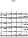
Figure 8] Figure 8 is a diagram illustrating the second processing method by the laser processing machine of the present embodiment. - [
Figure 9] Figure 9 is a diagram illustrating a third processing method by the laser processing machine of the present embodiment. - [
Figure 10] Figure 10 is a diagram illustrating the third processing method by the laser processing machine of the present embodiment. - [
Figure 11] Figure 11 is a diagram illustrating a fourth processing method by the laser processing machine of the present embodiment. - [
Figure 12] Figure 12 is a diagram illustrating a laser processing method by a first modification of the laser processing machine of the present embodiment. - [
Figure 13] Figure 13 is a diagram illustrating a laser processing method by a third modification of the laser processing machine of the present embodiment. - Hereinafter, the best embodiment for carrying out the present invention will be described using the drawings. Note that the following embodiment does not limit the invention as in the claims, and not all of the combinations of features described in the embodiment are essential to the solution of the invention.
-
Figure 1 is a schematic diagram illustrating a laser processing machine according to the embodiment of the present invention. - First,
Figure 1 will be referenced to give an outline of alaser processing machine 1 according to the embodiment of the present invention. Thelaser processing machine 1 according to the present embodiment is a laser processing machine that engraves, in a surface of a workpiece W, a matrix-type two-dimensional code in which a first cell as a unit irradiation area and a second cell as a unit non-irradiation area are arranged in a desired array pattern in a first direction and a second direction orthogonal to the first direction. - Note that in the present embodiment, the first direction is a Y-axis direction in
Figure 1 and the second direction is an X-axis direction inFigure 1 , but the directions are not limited thereto. - A matrix-type two-dimensional code is a two-dimensional code having an array pattern of n rows and m columns (where n and m are integers equal to or greater than 2) in which square first and second cells are plurally arranged in a freely chosen array. Specifically, a matrix-type two-dimensional is a square or rectangular two-dimensional code such as a QR Code® or a Data Matrix.
- The
laser processing machine 1 includes alaser processing head 30 that irradiates a workpiece W with a laser beam L and amoving mechanism 20 that moves the laser beam L radiated from thelaser processing head 30 in a first direction and a second direction, in which each first cell is irradiated with the laser beam L along both the first direction and the second direction. Thelaser processing machine 1 also includes alaser oscillator 10 that generates and emits the laser beam L, aprocess fiber 12 that conveys the laser beam L emitted by thelaser oscillator 10 to thelaser processing head 30, a processing table 21 on which the workpiece W is mounted, acontrol device 50, and an assist gas supply device (not illustrated). - The
laser oscillator 10 generates the laser beam L, and supplies the laser beam L to thelaser processing head 30 via theprocess fiber 12. The laser oscillator suitably used as thelaser oscillator 10 is, for example, a type in which a seed light emitted by a laser diode excites and amplifies Yb or the like in a resonator to emit the laser beam L at a predetermined wavelength, or a type that directly uses the laser beam L emitted by a laser diode. Examples of thelaser oscillator 10 as a solid-state laser oscillator include a fiber laser oscillator, a YAG laser oscillator, a disk laser oscillator, a DDL oscillator, and the like. - The
laser oscillator 10 emits the laser beam L in a 1 µm band with a wavelength of 900 nm to 1100 nm. For example, the DDL oscillator emits the laser beam L with a wavelength of 910 nm to 950 nm, while the fiber laser oscillator emits the laser beam L with a wavelength of 1060 nm to 1080 nm. - The
moving mechanism 20 is configured to drive at least one of thelaser processing head 30 or the processing table 21 so that thelaser processing head 30 and the processing table 21 move relative to one another. Specifically, themoving mechanism 20 includes anX-axis carriage 22 and a Y-axis carriage 23. TheX-axis carriage 22 is configured in a gate type, is disposed straddling the processing table 21, and is configured to be freely movable over the processing table 21 in the X-axis direction. The Y-axis carriage 23 is attached to theX-axis carriage 22 and is configured to be freely movable in the Y-axis direction perpendicular to the X-axis direction. Also, thelaser processing head 30 is attached to an end of the Y-axis carriage 23. By being provided with such a configuration, themoving mechanism 20 is configured to move thelaser processing head 30 in the X-axis direction, the Y-axis direction, or any combined direction of the X and Y axes, along the surface of the workpiece W mounted on the processing table 21. - Note that instead of moving the
laser processing head 30 along the surface of the workpiece W, themoving mechanism 20 may also be configured such that a position of thelaser processing head 30 is fixed and the workpiece W is moved relative to thelaser processing head 30. -
Figure 2 is a schematic diagram illustrating the laser processing head of the present embodiment. - The
laser processing head 30 irradiates the workpiece W on the processing table 21 with the laser beam L conveyed from thelaser oscillator 10 via theprocess fiber 12. Specifically, as illustrated inFigure 2 , thelaser processing head 30 includes ahousing 30a including an irradiation center axis of the laser beam L, and inside thishousing 30a, thelaser processing head 30 includes acollimating lens 31 entered by the laser beam L emitted from the emitting end of theprocess fiber 12, agalvano scanner unit 32 that functions as a beam vibrating mechanism, and abend mirror 35 by which the laser beam L emitted from thegalvano scanner unit 32 is reflected downward in a Z-axis direction perpendicular to the X and Y axes. Thelaser processing head 30 also includes acondensing lens 36 that focuses the laser beam L reflected by thebend mirror 35 - A tip portion of the
housing 30a is provided with anozzle 30b having a circular aperture for irradiating the workpiece W with the laser beam L. Thisnozzle 30b has a nozzle function for directing a flow of gas supplied from the assist gas supply device to the workpiece W coaxially with the laser beam L in order to remove the molten workpiece W, and is detachably provided on thehousing 30a. - The condensing
lens 36 is configured to move freely in directions approaching the workpiece W and going away from the workpiece W by means of a drive section and a moving mechanism not illustrated, in order to adjust a focal position of the laser beam L. - The
galvano scanner unit 32 includes afirst scanning section 33 and asecond scanning section 34, and is configured to vibrate the laser beam L. Thefirst scanning section 33 includes afirst scanning mirror 33a to reflect the laser beam L emitted by thecollimating lens 31 and afirst drive section 33b to rotate thefirst scanning mirror 33a to be at a predetermined angle. Thesecond scanning section 34 includes asecond scanning mirror 34a to reflect the laser beam L emitted from thefirst scanning mirror 33a and asecond drive section 34b to rotate thesecond scanning mirror 34a to be at a predetermined angle. - The
first drive section 33b and thesecond drive section 34b can reciprocally vibrate thefirst scanning mirror 33a and thesecond scanning mirror 34a in a predetermined angular range, respectively, on the basis of control by thecontrol device 50. By being provided with such a configuration, thegalvano scanner unit 32 can vibrate the laser beam L radiated from thelaser processing head 30 to the workpiece W by reciprocally vibrating one or both of thefirst scanning mirror 33a and thesecond scanning mirror 34a. - The
galvano scanner unit 32 may vibrate the laser beam L in a direction orthogonal to the movement direction of the laser beam L, and may also vibrate the laser beam L in the movement direction of the laser beam L and the direction orthogonal to the movement direction of the laser beam L. - Note that the
galvano scanner unit 32 is an example of a beam vibrating mechanism, and the beam vibrating mechanism is not limited to thegalvano scanner unit 32 that includes thefirst scanning section 33 and thesecond scanning section 34. -
Figure 3 is a functional block diagram schematically illustrating a control device of the present embodiment. - The
control device 50 is an example of a control device that controls each section of thelaser processing machine 1. As illustrated inFigure 3 , thecontrol device 50 includes aninput unit 51, adisplay unit 52, acontrol unit 53, and astorage unit 54. - The
input unit 51 is formed by an input device such as a keyboard, a mouse, a push-button/switch, or the like. By operating theinput unit 51, in addition to functions for inputting information normally required in thelaser processing machine 1, it is possible to perform operations such as selecting a laser processing program described later in thestorage unit 54, for example. - The
display unit 52 includes a display as a display device, and in addition to the functions of a display screen normally required in thelaser processing machine 1, displays a selection screen for selecting a laser processing program, for example. Thedisplay unit 52 may also be configured as a touch panel that includes the functions of theinput unit 51. In the case where thedisplay unit 52 is configured as the touch panel, the user can input various information, such as the selection of a laser processing program, to thecontrol device 50 by operating thedisplay unit 52, for example. - Note that the configuration of the
input unit 51 and thedisplay unit 52 is not limited to the configuration described above, and insofar as the configuration has equivalent functions in place of theinput unit 51 and the display unit 52 (such as remotely usable display means and input means, for example), the configuration is not limited thereto. - The
control unit 53 includes amovement control unit 53a to control the movingmechanism 20, and alaser control unit 53b. Themovement control unit 53a is configured to control movement operations by theX-axis carriage 22 and the Y-axis carriage 23 of the movingmechanism 20. Thelaser control unit 53b is configured to be able to control the power, intensity, and focal point adjustment of the laser beam L radiated from thelaser processing head 30, and the driving of afirst drive section 33b and asecond drive section 34b of thegalvano scanner unit 32 of thelaser processing head 30. - The
control unit 53 provided with such a configuration uses the movingmechanism 20 to move the laser beam L along one of either the first direction or the second direction while using thegalvano scanner unit 32 to vibrate the laser beam L along the other of either the first direction or the second direction. Also, thecontrol unit 53 controls the movingmechanism 20 such that the first cell is irradiated with the laser beam L along the first direction and then irradiated with the laser beam L again along the second direction. - Specifically, the
control unit 53 controls the movingmechanism 20 such that the first cells arranged in either the same row or column are each irradiated with the laser beam L consecutively along the first direction, and then the first cells arranged in the other of either the same row or column are each irradiated with the laser beam L consecutively along the second direction. - The
storage unit 54 includes a storage medium such as RAM, ROM, an HDD, or an SSD, and stores various data in a readable and writable way. Thestorage unit 54 stores programs required for control of each unit of thecontrol device 50. Thestorage unit 54 also stores a laser processing program for causing thecontrol unit 53 to execute control of thelaser processing machine 1. The laser processing program is configured to cause thecontrol unit 53 to perform an engraving process of irradiating each of the first cells with the laser beam L along both the first direction and the second direction. - Also, the laser processing program is configured to cause the
control unit 53 to execute a two-time processing process of irradiating the first cells with the laser beam L along the first direction and then irradiating the first cells with the laser beam L again along the second direction. - The
laser processing machine 1 provided with the above configuration can use the movingmechanism 20 to move thelaser processing head 30 relative to the workpiece W and use the galvano scanner unit 32 (beam vibrating mechanism) of thelaser processing head 30 to vibrate the laser beam L with which the workpiece W is irradiated, and thereby engrave a highly distinctive matrix-type two-dimensional code on the workpiece W in a short time. - A matrix-type two-dimensional code laser processing method by the
laser processing machine 1 according to the present embodiment will be described. In outline, the laser processing method according to the present embodiment is a laser processing method that irradiates each of the first cells with the laser beam L along both the first direction and the second direction. The laser processing method according to the present embodiment irradiates the first cells with the laser beam L along the first direction and then irradiates the first cells with the laser beam L again along the second direction. - Next, the laser processing method according to the present embodiment will be described in detail. Note that the
laser processing machine 1 according to the present embodiment is also capable of engraving a matrix-type two-dimensional code according to a method other than first through fourth laser processing methods indicated below. - In outline, in the first processing method, the
control unit 53 of thecontrol device 50 controls the movingmechanism 20 to: irradiate, with the laser beam L, first cells in a j-th column (where j is an integer equal to or greater than 1 and less than m) along a first forward direction, and then irradiate, with the laser beam L, first cells in a column other than the j-th column along a first reverse direction; and irradiate, with the laser beam L, first cells in an i-th row (where i is an integer equal to or greater than 1 and less than n) along a second reverse direction, and then irradiate, with the laser beam L, first cells in a row other than the i-th row along a second forward direction. -
Figure 4 is a diagram illustrating areas of a matrix-type two-dimensional code of the present embodiment. -
Figure 5 is a diagram illustrating a first processing method by the laser processing machine of the present embodiment. Arrows inFigure 5 indicate the movement directions of the laser processing head 30 (laser beam L). - First, as illustrated in
Figures 4 and5 , thelaser processing machine 1 irradiates the first cells with the laser beam L from the first direction. Specifically, thelaser processing machine 1 uses the movingmechanism 20 to move thelaser processing head 30 from cell C1,1 to cell Cn,1 in the first column along the first forward direction, and irradiates each first cell in the first column with the laser beam L. Next, thelaser processing machine 1 uses the movingmechanism 20 to move thelaser processing head 30 from cell Cn,2 to cell C1,2 in a second column along the first reverse direction, and irradiates each first cell in the second column with the laser beam L. The above is repeated similarly to the m-th column. -
Figure 6 is a diagram illustrating the first processing method by a laser processing machine of the present embodiment. Arrows inFigure 6 indicate the movement directions of the laser processing head 30 (laser beam L). - Thereafter, as illustrated in
Figures 4 and6 , thelaser processing machine 1 irradiates, with the laser beam L, the first cell from the second reverse and forward directions in order starting from the row containing the cell that the laser processing head 30 (laser beam L) last passed. Specifically, in a case where the matrix-type two-dimensional code has an odd number of columns (m is an odd number), thelaser processing machine 1 uses the movingmechanism 20 to move thelaser processing head 30 from cell Cn,m to cell Cn,1 in the n-th row along the second reverse direction, and irradiates each first cell in the n-th row with the laser beam L. Next, thelaser processing machine 1 uses the movingmechanism 20 to move thelaser processing head 30 from cell Cn-1,1 to cell Cn-1,m in the (n-1)-th row along the second forward direction, and irradiates each first cell in the second row with the laser beam L. A matrix-type two-dimensional code is engraved in the workpiece W by similarly repeating the above to the first row. - Also, in the case where the matrix-type two-dimensional code has an even number of columns (m is an even number), the
laser processing machine 1 uses the movingmechanism 20 to move thelaser processing head 30 from cell C1,m to cell C1,1 in the first row along the second reverse direction, and irradiates each first cell in the first row with the laser beam L. Next, thelaser processing machine 1 uses the movingmechanism 20 to move thelaser processing head 30 from cell C2,1 to cell C2,m in the second row along the second forward direction, and irradiates each first cell in the second row with the laser beam L. A matrix-type two-dimensional code is engraved in the workpiece W by similarly repeating the above to the n-th row. According to the above steps, the first laser processing method by thelaser processing machine 1 according to the present embodiment is performed. - In outline, in the second laser processing method, the
control unit 53 of thecontrol device 50 controls the movingmechanism 20 to: irradiate, with the laser beam L, first cells in the j-th column along the first forward direction, and then irradiate, with the laser beam L, first cells in a column other than the j-th column along the first forward direction; and irradiate, with the laser beam L, first cells in the i-th row along the second reverse direction, and then irradiate, with the laser beam L, first cells in a row other than the i-th row along the second reverse direction. -
Figure 7 is a diagram illustrating the second processing method by the laser processing machine of the present embodiment. Arrows inFigure 7 indicate the movement directions of the laser processing head 30 (laser beam L). - First, as illustrated in
Figures 4 and7 , thelaser processing machine 1 irradiates the first cells with the laser beam L from the first direction. Specifically, thelaser processing machine 1 uses the movingmechanism 20 to move thelaser processing head 30 from cell C1,1 to cell Cn,1 in the first column along the first forward direction, and irradiates each first cell in the first column with the laser beam L. Next, thelaser processing machine 1 uses the movingmechanism 20 to move thelaser processing head 30 from cell C1,2 to cell Cn,2 in the second column along the first forward direction, and irradiates each first cell in the second column with the laser beam L. The above is repeated similarly to the m-th column. -
Figure 8 is a diagram illustrating the second processing method by the laser processing machine of the present embodiment. Arrows inFigure 8 indicate the movement directions of the laser processing head 30 (laser beam L). - Thereafter, as illustrated in
Figures 4 and8 , thelaser processing machine 1 irradiates the first cells with the laser beam L from the second direction. Specifically, thelaser processing machine 1 uses the movingmechanism 20 to move thelaser processing head 30 from cell Cn,m to cell Cn,1 in the n-th row along the second reverse direction, and irradiates each first cell in the n-th row with the laser beam L. Next, thelaser processing machine 1 uses the movingmechanism 20 to move thelaser processing head 30 from cell Cn-1,m to cell Cn-1,1 in the (n-1)-th row along the second reverse direction, and irradiates each first cell in the (n-1)-th row with the laser beam L. A matrix-type two-dimensional code is engraved in the workpiece W by similarly repeating the above to the first row. According to the above steps, the second laser processing method by thelaser processing machine 1 according to the present embodiment is performed. - In outline, the third processing method and the fourth processing method are laser processing methods that irradiate first cells with the laser beam L in alternation from the first direction and the second direction. The
control unit 53 of thecontrol device 50 controls the movingmechanism 20 to, for example: irradiate, with the laser beam L, first cells in the j-th column along the first direction, and then irradiate, with the laser beam L, first cells in the i-th row along the second direction; and irradiate, with the laser beam L, first cells in a column other than the j-th column along the first direction, and then irradiate, with the laser beam L, first cells in a row other than the i-th row along the second direction. Hereinafter, the third processing method and the fourth processing method will be described in detail. -
Figure 9 is a diagram illustrating the third processing method by the laser processing machine of the present embodiment. Arrows inFigure 9 indicate the movement directions of the laser processing head 30 (laser beam L). - In outline, as illustrated in
Figures 4 and9 , in the third processing method, thecontrol unit 53 of thecontrol device 50 controls the movingmechanism 20 to: irradiate, with the laser beam L, first cells in the j-th column along the first forward direction, and then irradiate, with the laser beam L, first cells in the (i+1)-th row along the second forward direction; and irradiate, with the laser beam L, first cells in the (j+1)-th column along the first forward direction, and then irradiate, with the laser beam L, first cells in the i-th row along the second forward direction. -
Figure 10 is a diagram illustrating the third processing method by the laser processing machine of the present embodiment. Arrows inFigure 10 indicate the movement directions of the laser processing head 30 (laser beam L). - First, as illustrated in
Figures 4 and10 , thelaser processing machine 1 irradiates the first cells with the laser beam L from the first direction. Specifically, thelaser processing machine 1 uses the movingmechanism 20 to move thelaser processing head 30 from cell C1,1 to cell Cn,1 in the first column along the first forward direction, and irradiates each first cell in the first column with the laser beam L. Next, thelaser processing machine 1 irradiates the first cells with the laser beam L from the second direction. Specifically, thelaser processing machine 1 uses the movingmechanism 20 to move thelaser processing head 30 from cell Cn,1 to cell Cn,m in the n-th row along the second forward direction, and irradiates each first cell in the n-th row with the laser beam L. - Subsequently, the
laser processing machine 1 uses the movingmechanism 20 to move thelaser processing head 30 from cell C1,2 to cell Cn,2 in the second column along the first forward direction, and irradiates each first cell in the second column with the laser beam L. Thereafter, thelaser processing machine 1 uses the movingmechanism 20 to move thelaser processing head 30 from cell Cn-1,1 to cell Cn-1,m in the (n-1)-th row along the second forward direction, and irradiates each first cell in the (n-1)-th row with the laser beam L. - Similarly, each first cell in the j-th column is irradiated with the laser beam L along the first forward direction, and each first cell in the (i+1)-th row is irradiated with the laser beam L along the second forward direction. Also, each first cell in the (j+1)-th column is irradiated with the laser beam L along the first forward direction, and each first cell in the i-th row is irradiated with the laser beam L along the second forward direction. Further still, each first cell in the (j+1)-th column is irradiated with the laser beam L along the first forward direction and so on, and each first cell in all rows and columns is irradiated with the laser beam L, thereby engraving a matrix-type two-dimensional code in the workpiece W. According to the above steps, the third laser processing method by the
laser processing machine 1 according to the present embodiment is performed. - Note that the third laser processing method is not limited to the example described above. For example, the
laser processing machine 1 uses the movingmechanism 20 to move thelaser processing head 30 from cell C1,1 to cell Cn,1 in the first column along the first forward direction, and irradiates each first cell in the first column with the laser beam L. Next, thelaser processing machine 1 uses the movingmechanism 20 to move thelaser processing head 30 from cell C1,1 to cell C1,m in the first row along the second forward direction, and irradiates each first cell in the first row with the laser beam L. - Subsequently, the
laser processing machine 1 uses the movingmechanism 20 to move thelaser processing head 30 from cell C1,2 to cell Cn,2 in the second column along the first forward direction, and irradiates each first cell in the second column with the laser beam L. Thereafter, thelaser processing machine 1 uses the movingmechanism 20 to move thelaser processing head 30 from cell C2,1 to cell C2,m in the second row along the second forward direction, and irradiates each first cell in the second row with the laser beam L. - The third laser processing method may also be the following example. For example, the
laser processing machine 1 uses the movingmechanism 20 to move thelaser processing head 30 from cell C1,1 to cell Cn,1 in the first column along the first forward direction, and irradiates each first cell in the first column with the laser beam L. Next, thelaser processing machine 1 uses the movingmechanism 20 to move thelaser processing head 30 from cell Cn,1 to cell Cn,m in the n-th row along the second forward direction, and irradiates each first cell in the n-th row with the laser beam L. - Subsequently, the
laser processing machine 1 uses the movingmechanism 20 to move thelaser processing head 30 from cell C1,m to cell Cn,m in the m-th column along the first forward direction, and irradiates each first cell in the m-th column with the laser beam L. Thereafter, thelaser processing machine 1 uses the movingmechanism 20 to move thelaser processing head 30 from cell Cn-1,1 to cell Cn-1,m in the (n-1) -th row along the second forward direction, and irradiates each first cell in the (n-1)-th row with the laser beam L. - In outline, in the fourth processing method, the
control unit 53 of thecontrol device 50 controls the movingmechanism 20 to: irradiate, with the laser beam L, first cells in the j-th column along the first forward direction, and then irradiate, with the laser beam L, first cells in the (i+1)-th row along the second forward direction; and irradiate, with the laser beam L, first cells in the (j+1)-th column along the first reverse direction, and then irradiate, with the laser beam L, first cells in the i-th row along the second reverse direction. -
Figure 11 is a diagram illustrating the fourth processing method by the laser processing machine of the present embodiment. Arrows inFigure 11 indicate the movement directions of the laser processing head 30 (laser beam L). - First, as illustrated in
Figures 4 and11 , thelaser processing machine 1 irradiates the first cells with the laser beam L from the first direction. Specifically, thelaser processing machine 1 uses the movingmechanism 20 to move thelaser processing head 30 from cell C1,1 to cell Cn,1 in the first column along the first forward direction, and irradiates each first cell in the first column with the laser beam L. Next, thelaser processing machine 1 irradiates the first cells with the laser beam L from the second direction. Specifically, thelaser processing machine 1 uses the movingmechanism 20 to move thelaser processing head 30 from cell Cn,1 to cell Cn,m in the n-th row along the second forward direction, and irradiates each first cell in the n-th row with the laser beam L. - Subsequently, the
laser processing machine 1 uses the movingmechanism 20 to move thelaser processing head 30 from cell Cn,2 to cell C1,2 in the second column along the first reverse direction, and irradiates each first cell in the second column with the laser beam L. Thereafter, thelaser processing machine 1 uses the movingmechanism 20 to move thelaser processing head 30 from cell Cn-1,m to cell Cn-1,1 in the (n-1)-th row along the second reverse direction, and irradiates each first cell in the (n-1)-th row with the laser beam L. - Similarly, each first cell in the (j-1)-th column is irradiated with the laser beam L along the first forward direction, and each first cell in the i-th row is irradiated with the laser beam L along the second forward direction. Also, each first cell in the j-th column is irradiated with the laser beam L along the first reverse direction, and each first cell in the (i-1)-th row is irradiated with the laser beam L along the second reverse direction. Further still, each first cell in the (j+1)-th column is irradiated with the laser beam L along the first forward direction and so on, and each first cell in all rows and columns is irradiated with the laser beam L, thereby engraving a matrix-type two-dimensional code in the workpiece W. According to the above steps, the fourth laser processing method by the
laser processing machine 1 according to the present embodiment is performed. - Note that the fourth laser processing method is not limited to the example described above. For example, the
laser processing machine 1 uses the movingmechanism 20 to move thelaser processing head 30 from cell C1,1 to cell Cn,1 in the first column along the first forward direction, and irradiates each first cell in the first column with the laser beam L. Next, thelaser processing machine 1 uses the movingmechanism 20 to move thelaser processing head 30 from cell Cn,1 to cell Cn,m in the n-th row along the second forward direction, and irradiates each first cell in the n-th row with the laser beam L. - Subsequently, the
laser processing machine 1 uses the movingmechanism 20 to move thelaser processing head 30 from cell Cn,m-1 to cell C1,m-1 in the (m-1)-th column along the first reverse direction, and irradiates each first cell in the (m-1)-th column with the laser beam L. Thereafter, thelaser processing machine 1 uses the movingmechanism 20 to move thelaser processing head 30 from cell C2,m to cell C2,1 in the second row along the second reverse direction, and irradiates each first cell in the second row with the laser beam L. - The fourth laser processing method may also be the following example. For example, the
laser processing machine 1 uses the movingmechanism 20 to move thelaser processing head 30 from cell C1,1 to cell Cn,1 in the first column along the first forward direction, and irradiates each first cell in the first column with the laser beam L. Next, thelaser processing machine 1 uses the movingmechanism 20 to move thelaser processing head 30 from cell Cn-1,1 to cell Cn-1,m in the (n-1)-th row along the second forward direction, and irradiates each first cell in the (n-1)-th row with the laser beam L. - Subsequently, the
laser processing machine 1 uses the movingmechanism 20 to move thelaser processing head 30 from cell Cn,m-1 to cell C1,m-1 in the (m-1)-th column along the first reverse direction, and irradiates each first cell in the (m-1)-th column with the laser beam L. Thereafter, thelaser processing machine 1 uses the movingmechanism 20 to move thelaser processing head 30 from cell C1,m to cell C1,1 in the first row along the second reverse direction, and irradiates each first cell in the first row with the laser beam L. - As described above, the
laser processing machine 1 according to the present embodiment is a laser processing machine that engraves, in a surface of a workpiece W, a matrix-type two-dimensional code in which a first cell as a unit irradiation area and a second cell as a unit non-irradiation area are arranged in a desired array pattern in a first direction and a second direction orthogonal to the first direction, the laser processing machine being provided with alaser processing head 30 that irradiates the workpiece W with a laser beam L, a movingmechanism 20 that moves the laser beam L radiated from thelaser processing head 30 in the first direction and the second direction, and acontrol unit 53 that controls the movingmechanism 20, wherein each first cell is irradiated with the laser beam L along both the first direction and the second direction. - Additionally, by being provided with such a configuration, the
laser processing machine 1 according to the present embodiment has the advantage that the first cell is irradiated with the laser beam L along both the first direction and the second direction, whereby a two-dimensional code with high reading accuracy can be engraved in a short time. - Also, in the
laser processing machine 1 according to the present embodiment, thecontrol unit 53 controls the movingmechanism 20 such that the first cell is irradiated with the laser beam L along the first direction and then irradiated with the laser beam L again along the second direction. Providing such a configuration has the advantage of a short processing time, because the first cells arranged in either the same row or column are each irradiated with the laser beam L consecutively along the first direction, and then the first cells arranged in the other of either the same row or column are each irradiated with the laser beam L consecutively along the second direction. - Further, in the
laser processing machine 1 according to the present embodiment, the matrix-type two-dimensional code has an array pattern of n rows and m columns (where n and m are integers equal to or greater than 2), and thecontrol unit 53 controls the movingmechanism 20 to: irradiate, with the laser beam L, first cells in a j-th column (where j is an integer equal to or greater than 1 and less than m) along a first forward direction, and then irradiate, with the laser beam L, first cells in a column other than the j-th column along a first reverse direction; and irradiate, with the laser beam L, first cells in an i-th row (where i is an integer equal to or greater than 1 and less than n) along a second reverse direction, and then irradiate, with the laser beam L, first cells in a row other than the i-th row along a second forward direction. Providing such a configuration has the advantage that thelaser processing head 30 moves by turning back over rows or columns, whereby the processing time can be shortened further. - Further still, in the
laser processing machine 1 according to the present embodiment, the matrix-type two-dimensional code has an array pattern of n rows and m columns (where n and m are integers equal to or greater than 2), and thecontrol unit 53 controls the movingmechanism 20 to: irradiate, with the laser beam L, first cells in a j-th column (where j is an integer equal to or greater than 1 and less than m) along a first forward direction, and then irradiate, with the laser beam L, first cells in a column other than the j-th column along the first forward direction; and irradiate, with the laser beam L, first cells in an i-th row (where i is an integer equal to or greater than 1 and less than n) along a second reverse direction, and then irradiate, with the laser beam L, first cells in a row other than the i-th row along the second reverse direction. Providing such a configuration has the advantage that all first cells are irradiated with the laser beam L from the same directions, whereby uneven brightness of reflected light in each of the first cells can be suppressed. - Also, in the
laser processing machine 1 according to the present embodiment, the matrix-type two-dimensional code has an array pattern of n rows and m columns (where n and m are integers equal to or greater than 2), and thecontrol unit 53 controls the movingmechanism 20 to: irradiate, with the laser beam L, first cells in a j-th column (where j is an integer equal to or greater than 1 and less than m) along a first direction, and then irradiate, with the laser beam L, first cells in an i-th row (where i is an integer equal to or greater than 1 and less than n) along a second direction; and irradiate, with the laser beam L, first cells in a column other than the j-th column along the first direction, and then irradiate, with the laser beam L, first cells in a row other than the i-th row along the second direction. Providing such a configuration has the advantage that alternating processing is performed from the first direction and the second direction, whereby a distance moved by thelaser processing head 30 when moving to another row or column is shorter and the processing time can be reduced. - Further, in the
laser processing machine 1 according to the present embodiment, the matrix-type two-dimensional code has an array pattern of n rows and m columns (where n and m are integers equal to or greater than 2), and thecontrol unit 53 controls the movingmechanism 20 to: irradiate, with the laser beam L, first cells in a j-th column (where j is an integer equal to or greater than 1 and less than m) along a first forward direction, and then irradiate, with the laser beam L, first cells in an (i+1)-th row (where i is an integer equal to or greater than 1 and less than n) along a second forward direction; and irradiate, with the laser beam L, first cells in the (j+1)-th column along the first forward direction, and then irradiate, with the laser beam L, first cells in the i-th row along the second forward direction. Providing such a configuration has the advantage that a total distance moved by thelaser processing head 30 is shortened and all first cells are irradiated with the laser beam L from the same directions, whereby uneven brightness of reflected light in each of the first cells can be suppressed while shortening the processing time. - Also, the
laser processing machine 1 according to the present embodiment is provided with a beam vibrating mechanism (galvano scanner unit 32), wherein the beam vibrating mechanism (galvano scanner unit 32) is configured to vibrate the laser beam L, and thecontrol unit 53 uses the movingmechanism 20 to move the laser beam L along one of either the first direction or the second direction while using the beam vibrating mechanism (galvano scanner unit 32) to vibrate the laser beam L along the other of either the first direction or the second direction. Providing such a configuration has the advantage that a large area can be processed with a single laser irradiation. - Further, in the
laser processing machine 1 according to the present embodiment, the beam vibrating mechanism (galvano scanner unit 32) vibrates the laser beam L in a direction orthogonal to the movement direction of the laser beam L. Providing such a configuration has the advantage that processing can be performed to fill a first cell. - Further still, in the
laser processing machine 1 according to the present embodiment, the beam vibrating mechanism (galvano scanner unit 32) vibrates the laser beam L in the movement direction of the laser beam L and the direction orthogonal to the movement direction of the laser beam L. Providing such a configuration has the advantage that the periphery of the movement direction of the laser beam L can be evenly processed, and uneven brightness of reflected light in the first cells can be suppressed. - The above describes the preferred embodiment of the present invention, but the technical scope of the present invention is not limited to the scope indicated in the embodiment described above. Various changes or alterations can be applied to the embodiment described above.
- For example, in the embodiment described above, the
control unit 53 is described as controlling the movingmechanism 20 such that the first cells arranged in either the same row or column are each irradiated with the laser beam L consecutively along the first direction, and then the first cells arranged in the other of either the same row or column are each irradiated with the laser beam L consecutively along the second direction, but is not limited thereto. Thecontrol unit 53 may also not control the movingmechanism 20 for every first cell such that the first cell is irradiated with the laser beam L along the first direction and then irradiated with the laser beam L again along the second direction. - In the embodiment described above, the
control unit 53 is described as controlling the movingmechanism 20 to irradiate first cells with the laser beam L according to the first through fourth laser processing methods, but is not limited thereto, and may also control the movingmechanism 20 to irradiate first cells with the laser beam L according to laser processing methods other than the first through fourth laser processing methods. Laser processing methods other than the first through fourth laser processing methods include following first through fourth modifications, for example. - In outline, the
control unit 53 of thecontrol device 50 controls the movingmechanism 20 to: irradiate, with the laser beam L, first cells in the j-th column along the first forward direction, and then irradiate, with the laser beam L, first cells in a column other than the j-th column along the first reverse direction; and irradiate, with the laser beam L, first cells in the i-th row along the second forward direction, and then irradiate, with the laser beam L, first cells in a row other than the i-th row along the second reverse direction. - First, as illustrated in
Figures 4 and5 , thelaser processing machine 1 irradiates the first cells with the laser beam L from the first direction. Specifically, thelaser processing machine 1 uses the movingmechanism 20 to move thelaser processing head 30 from cell C1,1 to cell Cn,1 in the first column along the first forward direction, and irradiates each first cell in the first column with the laser beam L. Next, thelaser processing machine 1 uses the movingmechanism 20 to move thelaser processing head 30 from cell Cn,2 to cell C1,2 in the second column along the first reverse direction, and irradiates each first cell in the second column with the laser beam L. The above is repeated similarly to the m-th column. -
Figure 12 is a diagram illustrating the first modification of the laser processing method by the laser processing machine of the present embodiment. Arrows inFigure 12 indicate the movement directions of the laser processing head 30 (laser beam L). - Thereafter, as illustrated in
Figures 4 and12 , thelaser processing machine 1 irradiates the first cells with the laser beam L from the second direction. Specifically, thelaser processing machine 1 uses the movingmechanism 20 to move thelaser processing head 30 from cell C1,1 to cell C1,m in the first row along the second forward direction, and irradiates each first cell in the first row with the laser beam L. Next, thelaser processing machine 1 uses the movingmechanism 20 to move thelaser processing head 30 from cell C2,m to cell C2,1 in the second row along the second reverse direction, and irradiates each first cell in the second row with the laser beam L. A matrix-type two-dimensional code is engraved in the workpiece W by similarly repeating the above to the n-th row. According to the above steps, the first modification of the laser processing method by thelaser processing machine 1 according to the present embodiment is performed. - In outline, the
control unit 53 of thecontrol device 50 controls the movingmechanism 20 to: irradiate, with the laser beam L, first cells in the j-th column along the first forward direction, and then irradiate, with the laser beam L, first cells in a column other than the j-th column along the first reverse direction; and irradiate, with the laser beam L, first cells in the i-th row along the second forward direction in order starting from the row containing the cell that the laser processing head 30 (laser beam L) last passed, and then irradiate, with the laser beam L, first cells in a row other than the i-th row along the second reverse direction. - First, in a manner similar to the first modification, the
laser processing machine 1 irradiates the first cells with the laser beam L from the first direction. Specifically, thelaser processing machine 1 uses the movingmechanism 20 to move thelaser processing head 30 from cell C1,1 to cell Cn,1 in the first column along the first forward direction, and irradiates each first cell in the first column with the laser beam L. Next, thelaser processing machine 1 uses the movingmechanism 20 to move thelaser processing head 30 from cell Cn,2 to cell C1,2 in the second column along the first reverse direction, and irradiates each first cell in the second column with the laser beam L. The above is repeated similarly to the m-th column. - Thereafter, in a case where the matrix-type two-dimensional code has an odd number of columns, the
laser processing machine 1 uses the movingmechanism 20 to move thelaser processing head 30 from cell Cn,1 to cell Cn,m in the n-th row along the second forward direction, and irradiates each first cell in the n-th row with the laser beam L. Next, thelaser processing machine 1 uses the movingmechanism 20 to move thelaser processing head 30 from cell Cn-1,m to cell Cn-1,1 in the (n-1)-th row along the second reverse direction, and irradiates each first cell in the (n-1)-th row with the laser beam L. A matrix-type two-dimensional code is engraved in the workpiece W by similarly repeating the above to the first row. - Also, in a case where the matrix-type two-dimensional code has an even number of columns, the
laser processing machine 1 uses the movingmechanism 20 to move thelaser processing head 30 from cell C1,1 to cell C1,m in the first row along the second forward direction, and irradiates each first cell in the first row with the laser beam L. Next, thelaser processing machine 1 uses the movingmechanism 20 to move thelaser processing head 30 from cell C2,m to cell C2,1 in the second row along the second reverse direction, and irradiates each first cell in the second row with the laser beam L. A matrix-type two-dimensional code is engraved in the workpiece W by similarly repeating the above to the n-th row. According to the above steps, the second modification of the laser processing method by thelaser processing machine 1 according to the present embodiment is performed. - In outline, the
control unit 53 of thecontrol device 50 controls the movingmechanism 20 to: irradiate, with the laser beam L, first cells in the j-th column along the first forward direction, and then irradiate, with the laser beam L, first cells in a column other than the j-th column along the first forward direction; and irradiate, with the laser beam L, first cells in the i-th row along the second forward direction, and then irradiate, with the laser beam L, first cells in a row other than the i-th row along the second forward direction. - First, as illustrated in
Figures 4 and7 , thelaser processing machine 1 irradiates the first cells with the laser beam L from the first direction. Specifically, thelaser processing machine 1 uses the movingmechanism 20 to move thelaser processing head 30 from cell C1,1 to cell Cn,1 in the first column along the first forward direction, and irradiates each first cell in the first column with the laser beam L. Next, thelaser processing machine 1 uses the movingmechanism 20 to move thelaser processing head 30 from cell C1,2 to cell Cn,2 in the second column along the first forward direction, and irradiates each first cell in the second column with the laser beam L. The above is repeated similarly to the m-th column. -
Figure 13 is a diagram illustrating the third modification of the laser processing method by the laser processing machine of the present embodiment. Arrows inFigure 13 indicate the movement directions of the laser processing head 30 (laser beam L). - Thereafter, as illustrated in
Figures 4 and13 , thelaser processing machine 1 irradiates the first cells with the laser beam L from the second direction. Specifically, thelaser processing machine 1 uses the movingmechanism 20 to move thelaser processing head 30 from cell C1,1 to cell C1,m in the first row along the second forward direction, and irradiates each first cell in the first row with the laser beam L. Next, thelaser processing machine 1 uses the movingmechanism 20 to move thelaser processing head 30 from cell C2,1 to cell C2,m in the second row along the second forward direction, and irradiates each first cell in the second row with the laser beam L. A matrix-type two-dimensional code is engraved in the workpiece W by similarly repeating the above to the n-th row. According to the above steps, the third modification of the laser processing method by thelaser processing machine 1 according to the present embodiment is performed. - First, in a manner similar to the third modification, the
laser processing machine 1 irradiates the first cells with the laser beam L from the first direction. Specifically, thelaser processing machine 1 uses the movingmechanism 20 to move thelaser processing head 30 from cell C1,1 to cell Cn,1 in the first column along the first forward direction, and irradiates each first cell in the first column with the laser beam L. Next, thelaser processing machine 1 uses the movingmechanism 20 to move thelaser processing head 30 from cell C1,2 to cell Cn,2 in the second column along the first forward direction, and irradiates each first cell in the second column with the laser beam L. The above is repeated similarly to the m-th column. - Thereafter, the
laser processing machine 1 irradiates the first cells with the laser beam L from the second direction. Specifically, thelaser processing machine 1 uses the movingmechanism 20 to move thelaser processing head 30 from cell Cn,1 to cell Cn,m in the n-th row along the second forward direction, and irradiates each first cell in the first row with the laser beam L. Next, thelaser processing machine 1 uses the movingmechanism 20 to move thelaser processing head 30 from cell Cn-1,1 to cell Cn-1,m in the (n-1)-th row along the second forward direction, and irradiates each first cell in the (n-1)-th row with the laser beam L. A matrix-type two-dimensional code is engraved in the workpiece W by similarly repeating the above to the first row. According to the above steps, the fourth modification of the laser processing method by thelaser processing machine 1 according to the present embodiment is performed. - In the embodiment described above, the
laser processing machine 1 is described as being provided with a beam vibrating mechanism (galvano scanner unit 32), wherein the beam vibrating mechanism (galvano scanner unit 32) is configured to vibrate the laser beam L, and thecontrol unit 53 uses the movingmechanism 20 to move the laser beam L along one of either the first direction or the second direction while using the beam vibrating mechanism (galvano scanner unit 32) to vibrate the laser beam L along the other of either the first direction or the second direction, but thelaser processing machine 1 is not limited thereto. Thelaser processing machine 1 may also not be provided with the beam vibrating mechanism (galvano scanner unit 32). - In the embodiment described above, the beam vibrating mechanism (galvano scanner unit 32) is described as vibrating the laser beam L in the direction orthogonal to the movement direction of the laser beam L, or in the movement direction of the laser beam L and the direction orthogonal to the movement direction of the laser beam L, but is not limited thereto. The beam vibrating mechanism (galvano scanner unit 32) may also vibrate the laser beam L in the movement direction of the laser beam L.
- In the embodiment described above, the moving
mechanism 20 is described as being configured to drive at least one of thelaser processing head 30 and the processing table 21 so that thelaser processing head 30 and the processing table 21 move relative to one another, but is not limited thereto. For example, thelaser processing head 30 and the processing table 21 may both be fixed, and thegalvano scanner unit 32 may function as the movingmechanism 20 by moving the laser beam L radiated from thelaser processing head 30 in the first direction and the second direction. In the case where the movingmechanism 20 is configured to drive at least one of thelaser processing head 30 and the processing table 21 so that thelaser processing head 30 and the processing table 21 move relative to one another, a matrix-type two-dimensional code that is larger than the movable range of thegalvano scanner unit 32 can be engraved. -
- 1: laser processing machine
- 10: laser oscillator
- 12: process fiber
- 20: moving mechanism
- 21: processing table
- 22: X-axis carriage
- 23: Y-axis carriage
- 30: laser processing head
- 30a: housing
- 30b: nozzle
- 31: collimating lens
- 32: galvano scanner unit (beam vibrating mechanism)
- 33: first scanning section
- 33a: first scanning mirror
- 33b: first drive section
- 34: second scanning section
- 34a: second scanning mirror
- 34b: second drive section
- 35: bend mirror
- 36: condensing lens
- 50: control device
- 51: input unit
- 52: display unit
- 53: control unit
- 53a: movement control unit
- 53b: laser control unit
- 54: storage unit
- L: laser beam
- W: workpiece
Claims (14)
- A laser processing machine configured to engrave, in a surface of a workpiece, a matrix-type two-dimensional code in which a first cell as a unit irradiation area and a second cell as a unit non-irradiation area are arranged in a desired array pattern in a first direction and a second direction orthogonal to the first direction, the laser processing machine comprising:a laser processing head configured to irradiate the workpiece with a laser beam;a moving mechanism configured to move the laser beam radiated from the laser processing head in the first direction and the second direction; anda control unit configured to control the moving mechanism, whereinthe laser processing machine is configured to irradiate each first cell with the laser beam along both the first direction and the second direction.
- The laser processing machine according to claim 1, wherein
the control unit is configured to control the moving mechanism such that the first cell is irradiated with the laser beam along the first direction and then irradiated with the laser beam again along the second direction. - The laser processing machine according to claim 1 or 2, whereinthe matrix-type two-dimensional code has an array pattern of n rows and m columns (where n and m are integers equal to or greater than 2), andthe control unit is configured to control the moving mechanism to: irradiate, with the laser beam, first cells in a j-th column (where j is an integer equal to or greater than 1 and less than m) along a first forward direction, and then irradiate, with the laser beam, first cells in a column other than the j-th column along a first reverse direction; and irradiate, with the laser beam, first cells in an i-th row (where i is an integer equal to or greater than 1 and less than n) along a second reverse direction, and then irradiate, with the laser beam, first cells in a row other than the i-th row along a second forward direction.
- The laser processing machine according to claim 1 or 2, whereinthe matrix-type two-dimensional code has an array pattern of n rows and m columns (where n and m are integers equal to or greater than 2), andthe control unit is configured to control the moving mechanism to: irradiate, with the laser beam, first cells in a j-th column (where j is an integer equal to or greater than 1 and less than m) along a first forward direction, and then irradiate, with the laser beam, first cells in a column other than the j-th column along the first forward direction; and irradiate, with the laser beam, first cells in an i-th row (where i is an integer equal to or greater than 1 and less than n) along a second reverse direction, and then irradiate, with the laser beam, first cells in a row other than the i-th row along the second reverse direction.
- The laser processing machine according to claim 1 or 2, whereinthe matrix-type two-dimensional code has an array pattern of n rows and m columns (where n and m are integers equal to or greater than 2), andthe control unit is configured to control the moving mechanism to: irradiate, with the laser beam, first cells in a j-th column (where j is an integer equal to or greater than 1 and less than m) along the first direction, and then irradiate, with the laser beam, first cells in an i-th row (where i is an integer equal to or greater than 1 and less than n) along the second direction; and irradiate, with the laser beam, first cells in a column other than the j-th column along the first direction, and then irradiate, with the laser beam, first cells in a row other than the i-th row along the second direction.
- The laser processing machine according to claim 1 or 2, whereinthe matrix-type two-dimensional code has an array pattern of n rows and m columns (where n and m are integers equal to or greater than 2), andthe control unit is configured to control the moving mechanism to: irradiate, with the laser beam, first cells in a j-th column (where j is an integer equal to or greater than 1 and less than m) along a first forward direction, and then irradiate, with the laser beam, first cells in an (i+1)-th row (where i is an integer equal to or greater than 1 and less than n) along a second forward direction; and irradiate, with the laser beam, first cells in the (j+1)-th column along the first forward direction, and then irradiate, with the laser beam, first cells in the i-th row along the second forward direction.
- The laser processing machine according to claim 1 or 2, whereinthe matrix-type two-dimensional code has an array pattern of n rows and m columns (where n and m are integers equal to or greater than 2), andthe control unit is configured to control the moving mechanism to: irradiate, with the laser beam, first cells in a j-th column (where j is an integer equal to or greater than 1 and less than m) along a first forward direction, and then irradiate, with the laser beam, first cells in an (i+1)-th row (where i is an integer equal to or greater than 1 and less than n) along a second forward direction; and irradiate, with the laser beam, first cells in the (j+1)-th column along a first reverse direction, and then irradiate, with the laser beam, first cells in the i-th row along a second reverse direction.
- The laser processing machine according to any one of claims 1 to 7, comprising:a beam vibrating mechanism, whereinthe beam vibrating mechanism is configured to vibrate the laser beam, andthe control unit is configured to use the moving mechanism to move the laser beam along one of either the first direction or the second direction while using the beam vibrating mechanism to vibrate the laser beam along the other of either the first direction or the second direction.
- The laser processing machine according to claim 8, wherein
the beam vibrating mechanism is configured to vibrate the laser beam in a direction orthogonal to a movement direction of the laser beam. - The laser processing machine according to claim 8, wherein
the beam vibrating mechanism is configured to vibrate the laser beam in a movement direction of the laser beam and a direction orthogonal to the movement direction of the laser beam. - A laser processing method for engraving, in a surface of a workpiece, a matrix-type two-dimensional code in which a first cell as a unit irradiation area and a second cell as a unit non-irradiation area are arranged in a desired array pattern in a first direction and a second direction orthogonal to the first direction, the laser processing method comprising:
irradiating the each first cell with a laser beam along both the first direction and the second direction. - The laser processing method according to claim 11, wherein
the first cell is irradiated with the laser beam along the first direction and then irradiated with the laser beam again along the second direction. - A laser processing program for engraving, in a surface of a workpiece, a matrix-type two-dimensional code in which a first cell as a unit irradiation area and a second cell as a unit non-irradiation area are arranged in a desired array pattern in a first direction and a second direction orthogonal to the first direction, the laser processing program:
causing a control unit to perform an engraving process for irradiating the each first cell with a laser beam along both the first direction and the second direction. - The laser processing program according to claim 13, the laser processing program:
causing a control unit to perform a two-time processing process for irradiating the first cell with the laser beam along the first direction and then irradiating the first cell with the laser beam again along the second direction.
Applications Claiming Priority (2)
| Application Number | Priority Date | Filing Date | Title |
|---|---|---|---|
| JP2022009989A JP7333430B2 (en) | 2022-01-26 | 2022-01-26 | LASER MACHINE, LASER PROCESSING METHOD AND LASER PROCESSING PROGRAM |
| PCT/JP2022/047453 WO2023145335A1 (en) | 2022-01-26 | 2022-12-22 | Laser processing machine, laser processing method, and laser processing program |
Publications (2)
| Publication Number | Publication Date |
|---|---|
| EP4470709A1 true EP4470709A1 (en) | 2024-12-04 |
| EP4470709A4 EP4470709A4 (en) | 2025-07-09 |
Family
ID=87471668
Family Applications (1)
| Application Number | Title | Priority Date | Filing Date |
|---|---|---|---|
| EP22924182.3A Pending EP4470709A4 (en) | 2022-01-26 | 2022-12-22 | LASER PROCESSING MACHINE, LASER PROCESSING METHOD AND LASER PROCESSING PROGRAM |
Country Status (3)
| Country | Link |
|---|---|
| EP (1) | EP4470709A4 (en) |
| JP (1) | JP7333430B2 (en) |
| WO (1) | WO2023145335A1 (en) |
Family Cites Families (9)
| Publication number | Priority date | Publication date | Assignee | Title |
|---|---|---|---|---|
| JP2680256B2 (en) * | 1993-12-27 | 1997-11-19 | 川崎重工業株式会社 | Laser processing equipment |
| JPH10175084A (en) * | 1996-12-17 | 1998-06-30 | Komatsu Ltd | Line type laser marker device, its optical device and its engraving method |
| JP2001232848A (en) | 2000-02-18 | 2001-08-28 | Sunx Ltd | Device and method for laser marking |
| JP4255051B2 (en) * | 2002-10-11 | 2009-04-15 | Tdk株式会社 | Two-dimensional barcode printing method and apparatus |
| JP4943069B2 (en) * | 2006-06-29 | 2012-05-30 | 株式会社キーエンス | Laser processing equipment, laser processing condition setting equipment |
| JP2009083249A (en) * | 2007-09-28 | 2009-04-23 | Sony Corp | Laser marking method |
| JP2017094388A (en) * | 2015-11-28 | 2017-06-01 | 菊池紙工株式会社 | Marking method and laser marking device of qr code |
| CN109534286A (en) * | 2018-11-05 | 2019-03-29 | 广州大学 | A kind of material surface nesting nanostructure and preparation method thereof |
| CN113579480B (en) * | 2021-07-29 | 2023-06-16 | 湖北工业大学 | Preparation method of composite structure for reducing light reflectivity of titanium alloy surface |
-
2022
- 2022-01-26 JP JP2022009989A patent/JP7333430B2/en active Active
- 2022-12-22 EP EP22924182.3A patent/EP4470709A4/en active Pending
- 2022-12-22 WO PCT/JP2022/047453 patent/WO2023145335A1/en not_active Ceased
Also Published As
| Publication number | Publication date |
|---|---|
| EP4470709A4 (en) | 2025-07-09 |
| JP7333430B2 (en) | 2023-08-24 |
| WO2023145335A1 (en) | 2023-08-03 |
| JP2023108769A (en) | 2023-08-07 |
Similar Documents
| Publication | Publication Date | Title |
|---|---|---|
| US5329090A (en) | Writing on silicon wafers | |
| CN101432094B (en) | Laser processing method and laser processing device | |
| CN100544877C (en) | Flexible scan field | |
| JP5062838B2 (en) | Laser marking device | |
| JP2526717B2 (en) | Laser processing equipment | |
| EP1987911A1 (en) | Laser machining apparatus | |
| JP4956107B2 (en) | Laser processing data generation apparatus, laser processing data generation method, computer program, and laser marking system | |
| JPH11167602A (en) | Laser marking method for 2D barcode | |
| CN1376100A (en) | Laser drilling processing method and processing device | |
| CN114746206B (en) | Coordinate pattern file making device, trajectory pattern making device and laser processing machine control method | |
| JP2004268144A (en) | Laser processing equipment | |
| JP2008006460A5 (en) | ||
| JP2006068762A (en) | Laser processing method and laser processing apparatus | |
| JP2015100808A (en) | Laser marking apparatus | |
| KR101026356B1 (en) | Laser scanning device | |
| JPWO2007077630A1 (en) | Laser processing apparatus, program creation apparatus, and laser processing method | |
| EP4470708A1 (en) | Laser processing machine, laser processing method, and laser processing program | |
| JP7333430B2 (en) | LASER MACHINE, LASER PROCESSING METHOD AND LASER PROCESSING PROGRAM | |
| JP2005131668A (en) | Laser beam machining apparatus and method for adjusting work distance | |
| JP2008006466A5 (en) | ||
| JP2012035297A (en) | Laser beam machining method and laser beam machining apparatus | |
| JP2003010987A (en) | Beam processing method and apparatus, and touch panel substrate manufacturing method | |
| KR20090022844A (en) | Laser Marking Device and Method | |
| JP4318669B2 (en) | Laser processing equipment | |
| CN113325671A (en) | Device and method for laser direct imaging on uneven surface of workpiece |
Legal Events
| Date | Code | Title | Description |
|---|---|---|---|
| STAA | Information on the status of an ep patent application or granted ep patent |
Free format text: STATUS: THE INTERNATIONAL PUBLICATION HAS BEEN MADE |
|
| PUAI | Public reference made under article 153(3) epc to a published international application that has entered the european phase |
Free format text: ORIGINAL CODE: 0009012 |
|
| STAA | Information on the status of an ep patent application or granted ep patent |
Free format text: STATUS: REQUEST FOR EXAMINATION WAS MADE |
|
| 17P | Request for examination filed |
Effective date: 20240725 |
|
| AK | Designated contracting states |
Kind code of ref document: A1 Designated state(s): AL AT BE BG CH CY CZ DE DK EE ES FI FR GB GR HR HU IE IS IT LI LT LU LV MC ME MK MT NL NO PL PT RO RS SE SI SK SM TR |
|
| DAV | Request for validation of the european patent (deleted) | ||
| DAX | Request for extension of the european patent (deleted) | ||
| REG | Reference to a national code |
Ref country code: DE Ref legal event code: R079 Free format text: PREVIOUS MAIN CLASS: B23K0026000000 Ipc: B23K0026352000 |
|
| A4 | Supplementary search report drawn up and despatched |
Effective date: 20250605 |
|
| RIC1 | Information provided on ipc code assigned before grant |
Ipc: B23K 26/362 20140101ALI20250530BHEP Ipc: B23K 26/14 20140101ALI20250530BHEP Ipc: B23K 26/082 20140101ALI20250530BHEP Ipc: B23K 26/352 20140101AFI20250530BHEP |
|
| GRAP | Despatch of communication of intention to grant a patent |
Free format text: ORIGINAL CODE: EPIDOSNIGR1 |
|
| STAA | Information on the status of an ep patent application or granted ep patent |
Free format text: STATUS: GRANT OF PATENT IS INTENDED |
|
| INTG | Intention to grant announced |
Effective date: 20260102 |
|
| GRAJ | Information related to disapproval of communication of intention to grant by the applicant or resumption of examination proceedings by the epo deleted |
Free format text: ORIGINAL CODE: EPIDOSDIGR1 |
|
| STAA | Information on the status of an ep patent application or granted ep patent |
Free format text: STATUS: REQUEST FOR EXAMINATION WAS MADE |