EP4467882A2 - Vorrichtung zum kochen von lebensmitteln - Google Patents
Vorrichtung zum kochen von lebensmitteln Download PDFInfo
- Publication number
- EP4467882A2 EP4467882A2 EP24205736.2A EP24205736A EP4467882A2 EP 4467882 A2 EP4467882 A2 EP 4467882A2 EP 24205736 A EP24205736 A EP 24205736A EP 4467882 A2 EP4467882 A2 EP 4467882A2
- Authority
- EP
- European Patent Office
- Prior art keywords
- cooking
- fumes
- filter
- cooking food
- path
- Prior art date
- Legal status (The legal status is an assumption and is not a legal conclusion. Google has not performed a legal analysis and makes no representation as to the accuracy of the status listed.)
- Pending
Links
Images


Classifications
-
- F—MECHANICAL ENGINEERING; LIGHTING; HEATING; WEAPONS; BLASTING
- F24—HEATING; RANGES; VENTILATING
- F24C—DOMESTIC STOVES OR RANGES ; DETAILS OF DOMESTIC STOVES OR RANGES, OF GENERAL APPLICATION
- F24C15/00—Details
- F24C15/20—Removing cooking fumes
- F24C15/2042—Devices for removing cooking fumes structurally associated with a cooking range e.g. downdraft
-
- F—MECHANICAL ENGINEERING; LIGHTING; HEATING; WEAPONS; BLASTING
- F24—HEATING; RANGES; VENTILATING
- F24C—DOMESTIC STOVES OR RANGES ; DETAILS OF DOMESTIC STOVES OR RANGES, OF GENERAL APPLICATION
- F24C15/00—Details
- F24C15/20—Removing cooking fumes
- F24C15/2035—Arrangement or mounting of filters
Definitions
- the present invention relates to an apparatus for cooking food, in accordance with the preamble of claim 1.
- the present invention relates to an apparatus for cooking food which integrates an oven, a hob and a hood of the type commercially known as a recessed or downdraft hood.
- some of such apparatuses have downdraft hoods integrated in the hob or alternatively in the top of a kitchen cabinet where the apparatus for cooking food is housed.
- Such a downdraft hood is configured to generate a descending current greater than the ascending speed of the fumes due to cooking so that such fumes are sucked towards an opening provided in the hob itself with motion having a downwards direction.
- document US 6,455,818 B1 shows an apparatus for cooking food comprising an oven and a hob arranged vertically above the oven.
- Such a hob has a central opening arranged between a plurality of cooking zones and is in fluid communication with a suction unit, positioned below the hob.
- the suction unit is configured to generate a negative pressure which results in a suction effect of the cooking fumes through the central slot.
- Said apparatus for cooking food comprises a filter unit arranged in the slot and vertically removable from the hob to carry out filter cleaning and replacing operations.
- such a filter unit extends vertically between the hob and the oven thus reducing the useful volume of the cooking chamber of the oven itself.
- the filter unit extending vertically between the hob and the oven prevents making oven cooking chambers which extend vertically up to near the hob. This limits the usability of the oven by the user.
- the inlet opening of the fumes being arranged in a central portion of the hob, reduces the useful surface area thereof usable for cooking food.
- This reduction of the useful surface cooking area is all the more disadvantageous if the hob is of the "free induction" type, i.e., if the entire surface of the hob can be used for cooking food.
- an object underlying the present invention is to provide an apparatus for cooking food capable of maximising the useful volume and surface area for cooking food.
- the present invention it is possible to provide an apparatus for cooking food having an oven cavity which, with the same installation conditions, allows to maximise the useful volume of the oven's cooking chamber. In particular, this is all the more advantageous if the apparatus of the present invention is installed in a modular cabinet of a kitchen having standard dimensions. In fact, in this configuration, thanks to the present invention it is possible to dedicate only a part of the available space of the cabinet to the apparatus for cooking food in accordance with the present invention while preserving the other parts both in terms of intended use and functionality.
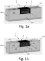
- the present invention relates to an apparatus for cooking food, indicated by 1 in the accompanying figures
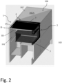
- the cooking apparatus 1 object of the present invention is configured to be recessed inside a special compartment 101 of a kitchen cabinet 100 having standard dimensions.
- the compartment can have a height of 360mm, a width of 900mm, and a depth which varies as a function of the specific applications.
- the kitchen cabinet envisages that its compartments are occupied by drawers 103, for example 360mm tall, arranged on opposite sides of the compartment 101, and a lower drawer 104 arranged vertically below the compartment 101.
- the kitchen cabinet 100 includes the apparatus for cooking food 1 which occupies a compartment of the cabinet 100.
- such an apparatus 1 for cooking food comprises an oven 2 having a cavity 3 and a door 4 associated to a front surface 3A of the cavity.
- the cavity 3 is configured to accommodate one or more foods to bake therein.
- the cavity 3 of the oven 2 has a width equal to 660mm, a height equal to 210mm and a depth equal to 405mm.
- the door 4 is configured to selectively provide access inside the cavity 3 of the oven 2 so as to allow the food to be cooked to be loaded and the cooked food to be unloaded.
- such a door 4 is constrained in rotation to the apparatus 1 so as to be able to switch it between a first configuration of use, for example of cooking, in which the door 4 closes the cavity 3 frontally, and a second configuration of use, for example of loading/unloading food, in which the cavity 3 is frontally accessible.
- the food loading/unloading configuration will also be indicated hereinafter as a maintenance configuration, as it allows the ordinary maintenance operations to be carried out on some components of the apparatus 1. More details on this will be provided later in the description.
- the apparatus 1 of the present invention further comprises a hob 6 having a predetermined width "L", length "l” and height "H.
- Such a hob 6 defines an upper surface 1A, which limits the apparatus 6 above, and a lower surface 1B, opposite the upper surface 1A.
- the upper surface 1A represents the visible or in-view side for the user while the lower surface 1B represents the surface hidden from the user's view, for example because it is recessed.
- the surface 1A is arranged seamlessly (i.e., continuously, uninterruptedly) with an outer surface 102A of a top 102 of the kitchen cabinet 100, as shown in figure 2 and in figure 1a .
- the hob 6 comprises at least one heating element 7 at which a container containing the food to be heated is available.
- the hob 6 comprises a plurality of heating elements 7 suitably distributed on the upper surface 1A and, in particular, capable of transmitting energy to the bottom of the containers in which the food to be heated is kept.
- the at least one heating element 7 is embodied in a resistive, or gas or, preferably, inductive heating element.
- the plurality of heating elements can be distributed on the upper surface 1A by means of a plurality of micro-inductors homogeneously distributed throughout the entire hob 6.
- the upper surface 1A is embodied in a sheet of glass or material having similar properties.
- the apparatus 1 of the present invention further comprises at least one inlet opening 8 on the upper surface 1A of the hob 6.
- the inlet opening 8 extends between the upper surface 1A and the lower surface 1B through the entire height "H" of the hob 6.
- the inlet opening 8 thus takes the form of a through hole in the hob 6.
- the inlet opening 8 is rectangular in shape and one of its two dimensions is much larger with respect to the other. Preferably its smaller dimension is between 2 - 3.5 cm.
- the apparatus 1 comprises two or more inlet openings 8 each of which is arranged near a respective perimeter edge P of the hob 6.
- the perimeter edge P comprises two side edges PL, which extend along the length "l" of the hob 6, a front edge PA extending along the width "L” of the hob 6 at the oven door 4, and a rear edge PP extending along the width "L” of the hob 6 opposite the front edge.
- the inlet openings can extend along the length "l" of the hob at both side edges, and along the width "L” only at the rear edge.
- the apparatus 1 further comprises an outlet opening 9 in fluid communication with the at least one inlet opening 8.
- Such an outlet opening 9 represents the ejection point of the sucked fumes.
- the apparatus 1 comprises a downdraft-type hood 10.
- the downdraft-type hood 10 can be operated in suction or filtering mode.
- the hood 10 in suction mode the hood 10 is configured to eject the cooking fumes in an environment outside the room in which the hood 10 is arranged, preferably an open environment, while in filtering mode the hood 10 ejects the cooking fumes inside the room in which the hood 10 is arranged.
- Such a downdraft hood 10 has one or more suction units 11 each of which is configured to suck the cooking fumes through the at least one inlet opening 8 and to eject them through a respective outlet opening 9.
- the suction unit 11 is configured to generate a negative pressure (less than atmospheric) responsible for the suction effect of the cooking fumes through the at least one inlet opening 8.
- the suction unit 11 comprises a conveyor 11a adapted to channel the cooking fumes.
- the apparatus 1 object of the present invention comprises a suction chamber 16 inside which the suction unit is arranged. Even more preferably, said suction chamber 16 contains the conveyor 11a entirely therein.
- Said suction chamber 16 comprises a bottom 16a shaped to collect fluids such as water/grease flowing from the inlet opening 8.
- the bottom can comprise a liquid collection basin (not shown) which can be removed from the suction chamber 16, or it can have a drainage tap (not shown) accessible by a user and arranged at a liquid collection cavity so as to allow the liquid accumulated therein to be emptied.
- a rib of predetermined height projecting from the bottom of the suction chamber 16 is included, which extends between the rear and front edge of the chamber itself along a direction perpendicular to both edges.
- the apparatus 1 comprises a duct system 12 comprising a first path of cooking fumes 12a.
- the sucked cooking fumes flowing along the first path of cooking fumes 12a flow between the at least one inlet opening 8 and the outlet opening 9.
- the first path of cooking fumes 12a fluid-dynamically connects the inlet opening 8 and the outlet opening 9.
- the duct system 12 is made of metallic material to better resist the heat emanating from the cavity 3 of the oven 2 during its operation.
- metallic material can be used instead of metallic.
- the duct system 12 comprises a path of the cooking fumes for each inlet opening 8. That is, the duct system 12 comprises a first and a second path of cooking fumes 12a, 12b each of which is associated to a respective inlet opening but with the same outlet opening.
- the present invention comprises two inlet openings 8
- the first and second paths of cooking fumes 12a, 12b are in fluid communication with the suction chamber upstream of the suction unit 11.
- said duct system 12 comprises a third and a fourth path of cooking fumes 12c, 12d respectively in fluid communication with the first and second path 12a, 12b.
- Such third and fourth paths of cooking fumes 12c, 12d are configured to conduct the sucked cooking fumes through the further inlet openings 8 to the outlet opening, through the first and second path of cooking fumes 12a, 12b.
- the apparatus 1 comprises a filter 13 for filtering the sucked cooking fumes.
- Such a filter 13 is preferably arranged in the first path of cooking fumes 12a of the duct system 12, in particular upstream of the suction unit 11.
- the cooking fumes once sucked through the at least one inlet opening 8 by the suction effect generated by the suction unit 11, then proceed along the first path of cooking fumes 12a passing through the filter 13 to thus reach the suction unit 11 and then the outlet opening 9.
- the second path of cooking fumes 12b comprises a respective filter 13 adapted to filter the cooking fumes flowing between the respective inlet openings 8 and the outlet opening 9. Therefore, in this case part of the cooking fumes will flow along the first path 12a and part along the second path 12b to then reach the suction unit 11 and then the outlet opening 9
- the duct 12 in which the filter is arranged is shaped to create a shape coupling with such a filter.
- the filter comprises a grease filter 13a configured to filter the greases present in the cooking fumes.
- the grease filter and is arranged transversely to a main extension direction Y-Y of the first path of cooking fumes 12a so as to maximise the surface of the grease filter 13a exposed to the cooking fumes flow.
- the grease filter is arranged in the duct so as to occupy the entire section, so that the entire flow is filtered.
- the grease filter 12a is made of a metal grille (or other material having similar features) retained by a metal or plastic profile arranged peripherally to the grille.
- the filter 13 comprises an odour filter 13b configured to filter the molecules responsible for the odours of the cooking fumes, eliminating them.
- said odour filter 13b is arranged downstream of the grease filter 13a, i.e., the flow of cooking fumes passes first through the grease filter 13a and then through the odour filter 13b.
- the odour filter 13b as well as the grease filter 13a is arranged in the duct so as to occupy the entire section thereof, so that the entire flow is filtered.
- the odour filter 13b comprises a set of filters housed in respective cavities of a filter holder element 131 extending along a main extension direction A-A.
- the odour filter 13b is an activated carbon filter.
- the grease filter 13a and the odour filter 13b are constrained together so as to be removable/insertable as a single filter.
- the grease filter 13a is separate and distinct from the odour filter 13b, i.e., each grease and odour filter is removable/insertable independently of the other, i.e., they are individually movable.
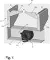
- the apparatus 1 comprises an extraction/insertion opening 14 configured to allow the extraction and insertion of the filter 13 inside the first path of cooking fumes 12a.
- the extraction/insertion opening 14 is sized to allow the extraction and insertion of the filter 13 inside the first path of cooking fumes 12a.
- Such an extraction/insertion opening 14 is preferably arranged on the front surface 3A of the cavity 3 of the oven 2, and the filter 13 is removable/insertable along a direction perpendicular to said front surface 3A.
- this extraction/insertion opening 14 is arranged laterally with respect to a perimeter contour F which surrounds an access mouth to the cavity 3 of the oven 2 on the front surface 3A.
- said extraction/insertion opening 14 is rectangular in shape and extends along a vertical direction at the filter 13, so as to allow the user to move the filter to and from the duct of the first path of fumes 12a.
- the extraction/insertion opening 14 can extend along the vertical direction Y-Y at both the grease filter 13a and the odour filter 13b, so as to allow the user to grasp and move them both or individually to and from the duct 12 in which they are housed.
- the opening 14 defines a surface, for example equal to 65x190mm.
- the extraction/insertion opening 14 extends along the vertical direction Y-Y only at the odour filter 13b so as to extract only the odour filter.
- the opening 14 defines a surface, for example equal to 65x50mm.
- the extraction/insertion opening 14 extends along the vertical direction Y-Y only at the odour filter 13b, then it is possible for the grease filter 13a to be extracted from the inlet opening 8 along a direction perpendicular to the hob, i.e., substantially parallel to the vertical direction Y-Y.
- the apparatus 1 object of the present invention comprises closing means 15 associated to the extraction/insertion opening 14 to tightly close it.
- the closing means 15 are shaped to hermetically plug the extraction/insertion opening 14 so as to prevent the creation of an air flow through the extraction/insertion opening 14, at least when the door 4 of the oven 2 is in the cooking configuration.
- closing means 15 have a surface which must be at least equal to or greater than that of the extraction/insertion opening 14.
- the closing means 15 are associated to the door 4 of the oven 2.
- the oven door 4 comprises a surface adapted to close the extraction/insertion opening 14 when the door 4 closes the cavity 3 of the oven 2, i.e., when the apparatus is in the cooking mode.
- the extraction/insertion opening 14 is closed by switching the oven door 4 from the food loading/unloading configuration to the cooking configuration.
- the closing means 15 are associated to the front surface 3A by pressure or hinging.
- the closing means 15 are a sort of 'cap' which snaps into the front surface 3A to close the extraction/insertion opening 14.
- the closing means 15 can be hinged to the front surface 3A, so that by rotating with respect to the front surface they are arranged at the extraction/insertion opening 14 to close it.
- the closing means 15 are associated to a head end 130 of the filter 13 which, abutting against the extraction/insertion opening 14, when the filter is housed in the duct 12, is able to completely close it.
- both the odour filter 13b and the grease filter 13a comprise a relative closing surface arranged at a head end adapted to close the extraction/insertion opening 14, when the filter 13 is housed in the duct 12.
- the closing means 15 comprise a closing surface 131a arranged at the head end 130 of the odour filter 13b only.
- Such a head end 130 is oriented transversely, preferably orthogonally, to the main extension direction A-A of the filter holder 131.
- the relative closing surface 131a arranged at a head end 130 of the odour filter 13b is adapted to close the extraction/insertion opening 14, when the filter 13b is housed in the duct 12.
- the closing means 15 are associated only with the head end 130 of the odour filter 13b while the grease filter 13a lacks them.
- the odour filter 13b by means of the relative closing surface 131a arranged at a head end 130, plugs the opening 14 and is removable/insertable through such an opening 14 while the grease filter 13 is removable/insertable from the respective inlet opening 8 (in the case of two or more inlet openings).
Landscapes
- Engineering & Computer Science (AREA)
- Chemical & Material Sciences (AREA)
- Combustion & Propulsion (AREA)
- Mechanical Engineering (AREA)
- General Engineering & Computer Science (AREA)
- Baking, Grill, Roasting (AREA)
- Electric Stoves And Ranges (AREA)
- Cookers (AREA)
- Table Devices Or Equipment (AREA)
Applications Claiming Priority (3)
| Application Number | Priority Date | Filing Date | Title |
|---|---|---|---|
| IT102021000002570A IT202100002570A1 (it) | 2021-02-05 | 2021-02-05 | Apparecchio per la cottura di pietanze |
| PCT/IB2022/050943 WO2022167966A1 (en) | 2021-02-05 | 2022-02-03 | Apparatus for cooking food |
| EP22706671.9A EP4288700B1 (de) | 2021-02-05 | 2022-02-03 | Vorrichtung zum kochen von lebensmitteln |
Related Parent Applications (1)
| Application Number | Title | Priority Date | Filing Date |
|---|---|---|---|
| EP22706671.9A Division EP4288700B1 (de) | 2021-02-05 | 2022-02-03 | Vorrichtung zum kochen von lebensmitteln |
Publications (2)
| Publication Number | Publication Date |
|---|---|
| EP4467882A2 true EP4467882A2 (de) | 2024-11-27 |
| EP4467882A3 EP4467882A3 (de) | 2025-01-29 |
Family
ID=75769707
Family Applications (2)
| Application Number | Title | Priority Date | Filing Date |
|---|---|---|---|
| EP24205736.2A Pending EP4467882A3 (de) | 2021-02-05 | 2022-02-03 | Vorrichtung zum kochen von lebensmitteln |
| EP22706671.9A Active EP4288700B1 (de) | 2021-02-05 | 2022-02-03 | Vorrichtung zum kochen von lebensmitteln |
Family Applications After (1)
| Application Number | Title | Priority Date | Filing Date |
|---|---|---|---|
| EP22706671.9A Active EP4288700B1 (de) | 2021-02-05 | 2022-02-03 | Vorrichtung zum kochen von lebensmitteln |
Country Status (8)
| Country | Link |
|---|---|
| US (1) | US20240102667A1 (de) |
| EP (2) | EP4467882A3 (de) |
| CN (1) | CN116964381A (de) |
| CA (1) | CA3206957A1 (de) |
| ES (1) | ES3004862T3 (de) |
| IT (1) | IT202100002570A1 (de) |
| PL (1) | PL4288700T3 (de) |
| WO (1) | WO2022167966A1 (de) |
Families Citing this family (1)
| Publication number | Priority date | Publication date | Assignee | Title |
|---|---|---|---|---|
| EP3951270A1 (de) * | 2020-08-05 | 2022-02-09 | Electrolux Appliances Aktiebolag | Kombinationsgerät |
Citations (1)
| Publication number | Priority date | Publication date | Assignee | Title |
|---|---|---|---|---|
| US6455818B1 (en) | 2001-08-23 | 2002-09-24 | Maytag Corporation | Downdraft filter assembly for a cooking appliance |
Family Cites Families (15)
| Publication number | Priority date | Publication date | Assignee | Title |
|---|---|---|---|---|
| US3587555A (en) * | 1969-05-13 | 1971-06-28 | Jenn Air Corp | Ventilated range |
| US3797375A (en) * | 1972-03-16 | 1974-03-19 | Jenn Air Corp | Stove with selectively interchangeable cooking apparatus |
| US3954427A (en) * | 1973-10-16 | 1976-05-04 | Jenn Air Corporation | Ventilation and filter module for cooking units |
| US4071738A (en) * | 1976-01-06 | 1978-01-31 | Jenn Air Corporation | Ventilated range with convertible radiant convection oven |
| DE2705395B2 (de) * | 1977-02-09 | 1980-08-07 | Bosch-Siemens Hausgeraete Gmbh, 7000 Stuttgart | Herd |
| US4411254A (en) * | 1981-04-24 | 1983-10-25 | The Jenn-Air Corporation | Countertop range with proximity ventilation and electronic air cleaner |
| DE3601460A1 (de) * | 1986-01-20 | 1987-07-23 | Gaggenau Werke | Vorrichtung zum abzug der wrasen an kuechengeraeten |
| CN203068623U (zh) * | 2012-12-14 | 2013-07-17 | 浙江科太厨房电器有限公司 | 一种防漏油的一体式环保灶 |
| US9897328B2 (en) * | 2013-05-02 | 2018-02-20 | William B. McEvoy | Tabletop cooking assembly |
| CN105805805B (zh) * | 2016-05-17 | 2019-05-14 | 浙江帅丰电器股份有限公司 | 一种风道易于清洁的集成灶 |
| DE102018130963A1 (de) * | 2018-12-05 | 2020-06-10 | Miele & Cie. Kg | Dunstabzugseinrichtung für eine Schrank- oder Küchenzeile |
| CN111486487A (zh) * | 2019-01-29 | 2020-08-04 | 宁波矢梁电子科技有限公司 | 一种蒸汽电磁集成灶 |
| US11236913B2 (en) * | 2019-11-27 | 2022-02-01 | Evo America, Llc | Air flow management for cooking system |
| CN111351095A (zh) * | 2020-04-29 | 2020-06-30 | 佛山市顺德区美的洗涤电器制造有限公司 | 集成灶 |
| DE202020103242U1 (de) * | 2020-06-05 | 2020-08-02 | Wesco Ag | Dunstabzugsvorrichtung und Kochfeldsystem |
-
2021
- 2021-02-05 IT IT102021000002570A patent/IT202100002570A1/it unknown
-
2022
- 2022-02-03 WO PCT/IB2022/050943 patent/WO2022167966A1/en not_active Ceased
- 2022-02-03 CA CA3206957A patent/CA3206957A1/en active Pending
- 2022-02-03 ES ES22706671T patent/ES3004862T3/es active Active
- 2022-02-03 US US18/275,432 patent/US20240102667A1/en active Pending
- 2022-02-03 EP EP24205736.2A patent/EP4467882A3/de active Pending
- 2022-02-03 PL PL22706671.9T patent/PL4288700T3/pl unknown
- 2022-02-03 EP EP22706671.9A patent/EP4288700B1/de active Active
- 2022-02-03 CN CN202280020856.8A patent/CN116964381A/zh active Pending
Patent Citations (1)
| Publication number | Priority date | Publication date | Assignee | Title |
|---|---|---|---|---|
| US6455818B1 (en) | 2001-08-23 | 2002-09-24 | Maytag Corporation | Downdraft filter assembly for a cooking appliance |
Also Published As
| Publication number | Publication date |
|---|---|
| ES3004862T3 (en) | 2025-03-13 |
| US20240102667A1 (en) | 2024-03-28 |
| CA3206957A1 (en) | 2022-08-11 |
| EP4288700B1 (de) | 2024-10-16 |
| EP4467882A3 (de) | 2025-01-29 |
| CN116964381A (zh) | 2023-10-27 |
| PL4288700T3 (pl) | 2025-03-17 |
| EP4288700C0 (de) | 2024-10-16 |
| EP4288700A1 (de) | 2023-12-13 |
| WO2022167966A1 (en) | 2022-08-11 |
| IT202100002570A1 (it) | 2022-08-05 |
Similar Documents
| Publication | Publication Date | Title |
|---|---|---|
| EP3593053B1 (de) | Ein kochfeld | |
| KR102800035B1 (ko) | 조리 제품 가열용 장치 | |
| EP3380791B1 (de) | Haube für den hausgebrauch | |
| CN110578943B (zh) | 烟雾排出装置和带有烟雾排出装置和灶台的组合设备 | |
| EP3951270A1 (de) | Kombinationsgerät | |
| EP3390918B1 (de) | Abzugshaube für den haushaltsgebrauch | |
| JP6790247B2 (ja) | 空気取入れ口を有する換気装置 | |
| EP3491296B1 (de) | Kochfeld | |
| CN112752926A (zh) | 炉灶系统和用于向下排出烹饪烟气的烟气排出装置 | |
| EP4288700B1 (de) | Vorrichtung zum kochen von lebensmitteln | |
| US20250334275A1 (en) | Appliance for cooking dishes | |
| US20250334274A1 (en) | Appliance for cooking dishes | |
| IT201800007763A1 (it) | Unita' per l'aspirazione dei fumi e vapori prodotti durante le operazioni di cottura di cibi e pietanze | |
| WO2023237969A1 (en) | Appliance for cooking dishes | |
| CN116529533A (zh) | 包括烹饪灶具和抽取装置的组合器具 | |
| WO2025172826A1 (en) | Cooking hob | |
| WO2025045525A1 (en) | Filter assembly for an extraction device and extraction device or combination appliance | |
| RU2024139138A (ru) | Прибор для приготовления блюд | |
| EA045882B1 (ru) | Варочная панель для приготовления пищи с вытяжкой | |
| IT201800003164U1 (it) | Unita' per l'aspirazione dei fumi e vapori prodotti durante le operazioni di cottura di cibi e pietanze |
Legal Events
| Date | Code | Title | Description |
|---|---|---|---|
| PUAI | Public reference made under article 153(3) epc to a published international application that has entered the european phase |
Free format text: ORIGINAL CODE: 0009012 |
|
| STAA | Information on the status of an ep patent application or granted ep patent |
Free format text: STATUS: THE APPLICATION HAS BEEN PUBLISHED |
|
| AC | Divisional application: reference to earlier application |
Ref document number: 4288700 Country of ref document: EP Kind code of ref document: P |
|
| AK | Designated contracting states |
Kind code of ref document: A2 Designated state(s): AL AT BE BG CH CY CZ DE DK EE ES FI FR GB GR HR HU IE IS IT LI LT LU LV MC MK MT NL NO PL PT RO RS SE SI SK SM TR |
|
| PUAL | Search report despatched |
Free format text: ORIGINAL CODE: 0009013 |
|
| AK | Designated contracting states |
Kind code of ref document: A3 Designated state(s): AL AT BE BG CH CY CZ DE DK EE ES FI FR GB GR HR HU IE IS IT LI LT LU LV MC MK MT NL NO PL PT RO RS SE SI SK SM TR |
|
| RIC1 | Information provided on ipc code assigned before grant |
Ipc: F24C 15/20 20060101AFI20241223BHEP |
|
| STAA | Information on the status of an ep patent application or granted ep patent |
Free format text: STATUS: REQUEST FOR EXAMINATION WAS MADE |
|
| 17P | Request for examination filed |
Effective date: 20250728 |