EP4465495A2 - Rotor für eine rotierende elektrische maschine - Google Patents
Rotor für eine rotierende elektrische maschine Download PDFInfo
- Publication number
- EP4465495A2 EP4465495A2 EP24175186.6A EP24175186A EP4465495A2 EP 4465495 A2 EP4465495 A2 EP 4465495A2 EP 24175186 A EP24175186 A EP 24175186A EP 4465495 A2 EP4465495 A2 EP 4465495A2
- Authority
- EP
- European Patent Office
- Prior art keywords
- rotor
- permanent magnets
- support cylinder
- main permanent
- radially
- Prior art date
- Legal status (The legal status is an assumption and is not a legal conclusion. Google has not performed a legal analysis and makes no representation as to the accuracy of the status listed.)
- Granted
Links
Images


Classifications
-
- H—ELECTRICITY
- H02—GENERATION; CONVERSION OR DISTRIBUTION OF ELECTRIC POWER
- H02K—DYNAMO-ELECTRIC MACHINES
- H02K1/00—Details of the magnetic circuit
- H02K1/06—Details of the magnetic circuit characterised by the shape, form or construction
- H02K1/22—Rotating parts of the magnetic circuit
- H02K1/27—Rotor cores with permanent magnets
- H02K1/2706—Inner rotors
- H02K1/272—Inner rotors the magnetisation axis of the magnets being perpendicular to the rotor axis
- H02K1/274—Inner rotors the magnetisation axis of the magnets being perpendicular to the rotor axis the rotor consisting of two or more circumferentially positioned magnets
- H02K1/2753—Inner rotors the magnetisation axis of the magnets being perpendicular to the rotor axis the rotor consisting of two or more circumferentially positioned magnets the rotor consisting of magnets or groups of magnets arranged with alternating polarity
- H02K1/278—Surface mounted magnets; Inset magnets
- H02K1/2783—Surface mounted magnets; Inset magnets with magnets arranged in Halbach arrays
-
- H—ELECTRICITY
- H02—GENERATION; CONVERSION OR DISTRIBUTION OF ELECTRIC POWER
- H02K—DYNAMO-ELECTRIC MACHINES
- H02K1/00—Details of the magnetic circuit
- H02K1/06—Details of the magnetic circuit characterised by the shape, form or construction
- H02K1/22—Rotating parts of the magnetic circuit
- H02K1/28—Means for mounting or fastening rotating magnetic parts on to, or to, the rotor structures
-
- H—ELECTRICITY
- H02—GENERATION; CONVERSION OR DISTRIBUTION OF ELECTRIC POWER
- H02K—DYNAMO-ELECTRIC MACHINES
- H02K7/00—Arrangements for handling mechanical energy structurally associated with dynamo-electric machines, e.g. structural association with mechanical driving motors or auxiliary dynamo-electric machines
- H02K7/003—Couplings; Details of shafts
-
- H—ELECTRICITY
- H02—GENERATION; CONVERSION OR DISTRIBUTION OF ELECTRIC POWER
- H02K—DYNAMO-ELECTRIC MACHINES
- H02K2213/00—Specific aspects, not otherwise provided for and not covered by codes H02K2201/00 - H02K2211/00
- H02K2213/09—Machines characterised by the presence of elements which are subject to variation, e.g. adjustable bearings, reconfigurable windings, variable pitch ventilators
Definitions
- the present invention relates to a rotor for a rotary electric machine.
- the present invention is advantageously applied to a rotary electric machine for automotive powering, which is installed on board a vehicle and can be utilized as a motor (absorbing electric energy and generating a mechanical driving torque) or as a generator (converting mechanical energy into electric energy).
- a rotary electric machine for automotive powering comprises a shaft, which is mounted in a rotatable manner so as to rotate around a central rotation axis, a rotor which generally has permanent magnets and is fitted to the shaft so as to rotate together with said shaft, and a stator arranged around the rotor so as to enclose, on the inside, said rotor.
- Patent applications EP4135164A1 , DE4107602A1 and US2022029487A1 describe a rotor for a rotary electric machine and comprising: a support cylinder, which has an outer surface and a central cavity; a plurality of permanent magnets, which are axially oriented, rest on the outer surface of the support cylinder, and are arranged beside one another so as to form a closed ring; and two end discs, which are arranged at the axially opposite ends of the support cylinder and define lateral edges of an annular seat containing the main permanent magnets. A radially outer portion of each end disc extending beyond the outer surface of the support cylinder is arranged at a non-zero axial distance from the corresponding permanent magnets.
- the object of the present invention is to provide a rotor for a rotary electric machine which has a simplified assembly of the permanent magnets in the rotor without simultaneously compromising the protection of said permanent magnets with respect to atmospheric agents.
- a rotor for a rotary electric machine is provided as claimed in the appended claims.
- reference numeral 1 indicates, as a whole, a synchronous electric machine for automotive powering of reversible type (i.e. which can operate both as an electric motor, absorbing electric energy and generating a mechanical driving torque, and as an electric generator, absorbing mechanical energy and generating electric energy).
- the electric machine 1 is intended to be installed in an electric or hybrid drive vehicle comprising at least two drive wheels (namely, in an electric or hybrid drive vehicle with two drive wheels or with four drive wheels).
- the electric machine 1 can be connected to the drive wheels (directly or by means of a transmission possibly provided with a clutch); namely, between the electric machine 1 and the drive wheels there can be a direct connection, there can be a simple speed reducer, or there can also be a clutch.
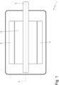
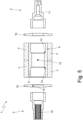
- the electric machine 1 comprises a shaft 2, which is mounted in a rotatable manner so as to rotate around a central rotation axis 3, a rotor 4 with permanent magnets which is fitted to the shaft 2 so as to rotate together with said shaft 2, and a stator 5 with a cylindrical tubular shape arranged around the rotor 4 so as to enclose, on the inside, said rotor 4.
- an air gap with an annular shape is defined, which has a reduced thickness (normally the bare minimum needed in order to allow the rotation of the rotor 4 inside the stator 5 in total safety).
- the rotor 4 comprises a plurality of permanent magnets 6, which are axially oriented and are arranged beside one another around the rotation axis 3 so as to form a closed ring.
- the permanent magnets 6 have a surface arrangement, namely are arranged at the outer surface of the rotor 4 and are not inserted in recesses obtained in the rotor 4.
- the sequence of permanent magnets 6 which constitutes the closed ring entails a circumferential arrangement according to a Halbach array so as to nullify the magnetic field radially on the inside of the permanent magnets 6 and so as to maximize the magnetic field radially on the outside of the permanent magnets 6.
- the permanent magnets 6 are arranged so as to nullify the magnetic field radially on the inside of the permanent magnets 6 (towards the shaft 2) and so as to maximize the magnetic field radially on the outside of the permanent magnets 6 (towards the magnetic core of the stator 5).
- the permanent magnets 6 are circumferentially arranged one following the other according to a Halbach array so as to nullify the magnetic field radially on the inside of the permanent magnets 6 and so as to maximize the magnetic field radially on the outside of the permanent magnets 6.
- a Halbach array is a particular joining (arrangement) of the permanent magnets 6, which are placed so as to strengthen the magnetic field along a face of the array (the radially outermost face in the present embodiment) and simultaneously cancel (nullify) by interference the magnetic field in the opposite face (the radially innermost face in the present embodiment).
- the Halbach array entails cyclically repeating sets of four permanent magnets 6: a permanent magnet 6 having a South-North orientation circumferentially arranged in a clockwise direction, a following permanent magnet 6 having a South-North orientation radially arranged towards the outside (namely, moving away from the central rotation axis 3), a following permanent magnet 6 having a South-North orientation circumferentially arranged in a counterclockwise direction, and a following permanent magnet 6 having a South-North orientation radially arranged towards the inside (namely, moving close to the central rotation axis 3).
- the permanent magnets 6 are not arranged according to a Halbach array.
- each permanent magnet 6 is not monolithic (namely, consisting from the beginning of one single piece of undivided and indivisible magnetic material), but is formed by an axial sequence of (smaller) permanent magnets 7 axially arranged in a single file one after the other, namely each permanent magnet 6 is formed by a plurality of (smaller) permanent magnets 7, which are axially arranged one after the other; in particular, in each permanent magnet 6, twenty to sixty permanent magnets 7 axially arranged in a single file one after the other are generally provided.
- each permanent magnet 6 all the permanent magnets 7 making up the permanent magnet 6 have the same identical orientation, namely are all equally oriented from the point of view of the magnetic field; in other words, in a same permanent magnet 6, the permanent magnets 7 making up the permanent magnet 6 have the magnetic field oriented in the same manner.
- the permanent magnets 6 alternatively have a cross section with a rectangular shape and a cross section with an isosceles trapezoidal shape; according to a different embodiment not illustrated, the permanent magnets 6 all have the same cross section with an isosceles trapezoidal shape (obviously with alternated orientations so as to make up the ring).
- the rotor 4 comprises a support cylinder 8, which houses the permanent magnets 6; in particular, the support cylinder 8 has an outer surface 9 on which the permanent magnets 6 rest.
- the permanent magnets 6 are arranged superficially on the outside of the support cylinder 8.
- the outer surface 9 of the support cylinder 8 is facetted, namely is made up of a plurality of flat faces, each of which provides a flat support to a corresponding permanent magnet 6.
- the support cylinder 8 is coupled to (namely constrained so as to be angularly integral with) the shaft 2 in order to form together one single cohesive block.
- the shaft 2 consists of two half-shafts 10 and 11, each of which is separate and distant from the other and is individually coupled (fixed) to the support cylinder 8; namely, each half-shaft 10 or 11 is independent of and separate from the other half-shaft 11 or 10 and is coupled (fixed) to the support cylinder 8 independently of the other half-shaft 11 or 10 (the two half-shafts 10 and 11 do not touch each other as they are arranged at a certain distance from each other).
- the support cylinder 8 is internally hollow and has a central through cavity 12 into which the two half-shafts 10 and 11 are inserted.
- each half-shaft 10 or 11 is driven through interference (in particular by means of a hot-cold coupling so as to obtain a high fastening force) into the support cylinder 8 (namely, into the central cavity 12 of the support cylinder 8).
- two annular abutments 13 are obtained against which the corresponding half-shafts 10 and 11 rest; namely, the two annular abutments 13 constitute limit stops (of the seats) for the insertion of the half-shafts 10 and 11 into the central cavity 12 of the support cylinder 8.
- the half-shaft 10 is shaped so as to be mounted on a support bearing; moreover, the half-shaft 10 is also shaped so as to be connected to a motion transmission system and thus has a spline machined surface.
- the half-shaft 11 is shaped so as to be mounted on another support bearing; moreover, the half-shaft 11 is also shaped so as to be connected to an angular position sensor (in particular, to a resolver).
- the rotor 4 comprises a pair of end discs 14 (also called balancing discs), which are arranged around the shaft 2 at the two opposite ends of the support cylinder 8 and are designed (among other things) to contain the permanent magnets 6.
- the two end discs 14 constitute the two opposite ends of the rotor 4 and define the lateral edges of an annular seat which contains the permanent magnets 6.
- the end discs 14 are designed to have balancing openings, which balance the rotor 4 around the rotation axis 3 and are manufactured by means of cylindrical drilling or by means of milling.
- balancing openings which balance the rotor 4 around the rotation axis 3 and are manufactured by means of cylindrical drilling or by means of milling.
- the two end discs 14 are utilized, which act as balancers thanks to calibrated asymmetries in their mass generated by the balancing openings (which can be dead openings or through openings and can be arranged in a radial or axial manner).
- the presence, the number, the arrangement and the depth of the balancing holes are absolutely random and can completely vary from rotor 4 to rotor 4, as they depend on the actual unbalance (due to the constructive tolerances) of the rotor 4 at the end of its manufacturing.
- a rotor 4 it is also possible for a rotor 4 to have no balancing holes at all, as, for a fortunate combination of the constructive tolerances, at the end of its manufacturing it has such a reduced unbalance around the rotation axis 3 that no corrections are required.
- Each end disc 14 centrally has a through hole 15 through which a corresponding half-shaft 10 or 11 is arranged (with contact), namely each end disc 14 is fitted around a corresponding half-shaft 10 or 11, which is arranged inside the through hole 15 of the end disc 14.
- each end disc 14 is fitted along a corresponding half-shaft 10 or 11 through its own through hole 15 so as to come into contact with the support cylinder 8.
- each end disc 13 is driven onto said corresponding half-shaft 10 or 11 through interference (in particular, by means of a hot-cold coupling so as to obtain a high fastening force); namely, each end disc 13 centrally has a through hole 15 into which the corresponding half-shaft 10 or 11 is inserted (by means of an interference coupling).
- Each end disc 14 has a larger diameter than a diameter of the support cylinder and extends beyond the outer surface 9 of the support cylinder 8 so as to define an axial containment of the permanent magnets 6; in other words, the two end discs 14 constitute outer edges of the support cylinder 8 which protrude from the outer surface 9 of the support cylinder 8 and delimit said outer surface 9 on both sides.
- the end discs 14 are in axial abutment against the support cylinder 8; namely, the end discs 14 axially " touch " the support cylinder 8 and not the permanent magnets 6 so as to axially press directly against the support cylinder 8, instead of pressing against the permanent magnets 6.
- the support cylinder 8 is axially (slightly, actually a few millimetres) longer than the permanent magnets 6 so as to come into contact with the end discs 14 before the permanent magnets 6.
- a radially outer portion of each end disc 14 extending beyond the outer surface 9 of the support cylinder 8 is arranged at a given non-zero axial distance D from the corresponding permanent magnets 6.
- an axially inner wall 16 of the radially outer portion of each end disc 14 is arranged at a given non-zero axial distance D from an axially outer wall 17 of the corresponding permanent magnets 6.
- This axial distance D between the axially inner wall 16 of the radially outer portion of each end disc 14 and the axially outer wall 17 of the corresponding permanent magnets 6 creates a space 18 that can initially be empty (when the permanent magnets 6 are radially inserted into the support cylinder 8) and is filled with a filler 19 (initially fluid and which solidifies in contact with the atmosphere), which is generally a glue or a resin.
- a filler 19 initially fluid and which solidifies in contact with the atmosphere
- the axial distance D is not constant but progressively decreases (linearly) from the outside to the inside (i.e. progressively decreases towards the rotation axis 3) and thus gives the space 18 a (truncated) "V" shape.
- the rotor 4 comprises a cylindrical and internally hollow containment element (not illustrated), which is arranged around the permanent magnets 6 so as to keep the permanent magnets 6 in contact with the support cylinder 8; namely, the containment element covers the permanent magnets 6 externally so as to provide a radial containment of said permanent magnets 6 in order to prevent the centrifugal force from being able to push the permanent magnets 6 against the magnetic core of the stator 5.
- the half-shaft 10 is made of high-strength steel (or another equivalent material in terms of mechanical features) since it must be able to transmit the torque generated or absorbed by the rotor 4; on the other hand, the half-shaft 11 is made of steel or another metal material having a lower strength than the steel of the half-shaft 10, since the half-shaft 11 does not transmit the torque generated or absorbed by the rotor 4.
- the support cylinder 8 is made of a ferromagnetic metal material (steel), of a non-magnetic metal material (such as stainless steel, aluminium, titanium or magnesium), or even of a non-metal material (typically, a composite material, such as carbon fibre, in order to have the necessary strength).
- a ferromagnetic metal material such as stainless steel, aluminium, titanium or magnesium
- a non-metal material typically, a composite material, such as carbon fibre, in order to have the necessary strength
- the end discs 14 are normally made of non-magnetic stainless steel so as to have the necessary strength, so as to allow the correct balancing of the rotor 4 (the end discs 14 must have a certain mass in order to be able to produce an effective balancing action by effect of the removal of material from said end discs 14) and, at the same time, so as not to disturb the magnetic field generated by the permanent magnets 6.
- each permanent magnet 6 the single permanent magnets 7 are glued to one another by means of the interposition of an assembly glue 20 (which constitutes an electrical insulator) so as to reduce energy losses due to eddy currents.
- each permanent magnet 6 is manufactured by gluing the single permanent magnets 7 to one another by means of the assembly glue 20 (which constitutes an electrical insulator).
- the permanent magnets 6 are directly mounted on the outer surface 9 of the support cylinder 8; in particular, each permanent magnet 6 is glued to the outer wall 9 of the support cylinder 8 by means of an assembly glue, which is preferably an electrical insulator (so as to avoid " short-circuiting " the various permanent magnets 7 of a same permanent magnet 6 through the outer wall 9 of the support cylinder 8).
- an electrically insulating layer consisting of the assembly glue is interposed between the outer wall 9 of the support cylinder 8 and the permanent magnets 6.
- the assembly glue has the function of electrically insulating the permanent magnets 6 from the underlying outer wall 9 of the support cylinder 8 and above all of connecting the permanent magnets 6 to the outer wall 9 of the support cylinder 8 during the construction of the rotor 4 (the mechanical restraint of the permanent magnets 6 is produced by the containment element, since the assembly glue is not capable of withstanding the centrifugal force when the rotor 4 rotates at high speed).
- the rotor 4 described above has numerous advantages.
- the rotor 4 described above allows mounting the permanent magnets 6 on the support cylinder 8 in a very simple manner since it allows inserting the permanent magnets 6 with a radial movement and without any effort thanks to the existing axial distance D between the end discs 14 and the permanent magnets 6.
- the permanent magnets 6 being rested with a radial movement against the outer surface 9 of the support cylinder 8 do not " rub " against the end discs 14 thanks to the axial distance D and therefore their radial insertion does not involve any effort.
- the spaces 18 are filled with the filler 19, which can be the same assembly glue 20 or can be a resin or a glue of a different type.
- V The flared (i.e. "V") shape of the spaces 18 performs a self-centring function, which facilitates the correct axial positioning of the permanent magnets 8 when they rest on the outer surface 9 of the support cylinder 8.
- the rotor 4 described above is easy to manufacture since it is composed of a reduced number of simply shaped pieces that can be quickly combined with one another also in automated processes.
Landscapes
- Engineering & Computer Science (AREA)
- Power Engineering (AREA)
- Permanent Field Magnets Of Synchronous Machinery (AREA)
Applications Claiming Priority (1)
| Application Number | Priority Date | Filing Date | Title |
|---|---|---|---|
| IT102023000010020A IT202300010020A1 (it) | 2023-05-18 | 2023-05-18 | Rotore per una macchina elettrica rotante |
Publications (3)
| Publication Number | Publication Date |
|---|---|
| EP4465495A2 true EP4465495A2 (de) | 2024-11-20 |
| EP4465495A3 EP4465495A3 (de) | 2024-12-25 |
| EP4465495B1 EP4465495B1 (de) | 2026-03-25 |
Family
ID=87418693
Family Applications (1)
| Application Number | Title | Priority Date | Filing Date |
|---|---|---|---|
| EP24175186.6A Active EP4465495B1 (de) | 2023-05-18 | 2024-05-10 | Rotor für eine rotierende elektrische maschine |
Country Status (3)
| Country | Link |
|---|---|
| US (1) | US20240388150A1 (de) |
| EP (1) | EP4465495B1 (de) |
| IT (1) | IT202300010020A1 (de) |
Citations (3)
| Publication number | Priority date | Publication date | Assignee | Title |
|---|---|---|---|---|
| DE4107602A1 (de) | 1991-03-09 | 1992-09-10 | Bosch Gmbh Robert | Permanentmagnetrotor fuer elektrische maschinen |
| US20220029487A1 (en) | 2019-04-10 | 2022-01-27 | Ihi Corporation | Motor rotor with surface treatment |
| EP4135164A1 (de) | 2021-08-12 | 2023-02-15 | FERRARI S.p.A. | Rotor für eine elektrische drehmaschine |
Family Cites Families (17)
| Publication number | Priority date | Publication date | Assignee | Title |
|---|---|---|---|---|
| US4729160A (en) * | 1985-08-14 | 1988-03-08 | Kollmorgen Technologies Corporation | Method for manufacturing a composite sleeve for an electric motor |
| DE3808331A1 (de) * | 1988-03-12 | 1989-09-28 | Kernforschungsanlage Juelich | Magnetische lagerung mit permanentmagneten zur aufnahme der radialen lagerkraefte |
| JP2002272034A (ja) * | 2001-03-07 | 2002-09-20 | Isuzu Ceramics Res Inst Co Ltd | マグネットロータ及びそれを備えた高出力交流機 |
| US8040007B2 (en) * | 2008-07-28 | 2011-10-18 | Direct Drive Systems, Inc. | Rotor for electric machine having a sleeve with segmented layers |
| FR2986919B1 (fr) * | 2012-02-10 | 2016-04-22 | Converteam Tech Ltd | Moteur electrique a grande vitesse |
| TWI751968B (zh) * | 2015-03-24 | 2022-01-11 | 日商日東電工股份有限公司 | 稀土類永久磁石形成用燒結體及具有稀土類永久磁石之旋轉電機 |
| JP6527102B2 (ja) * | 2016-04-22 | 2019-06-05 | ファナック株式会社 | 保持部材、これを備える回転電機の回転子、及びそれを備える回転電機 |
| JP6464117B2 (ja) * | 2016-06-24 | 2019-02-06 | ファナック株式会社 | 回転子部材、回転子、及び電動機 |
| US20190207448A1 (en) * | 2016-07-13 | 2019-07-04 | Ihi Corporation | Motor rotor, turbocharger, and method of manufacturing motor rotor |
| JP6730233B2 (ja) * | 2017-07-26 | 2020-07-29 | ファナック株式会社 | 回転子、回転電機及び回転子の製造方法 |
| FR3076674B1 (fr) * | 2018-01-09 | 2022-03-04 | Whylot Sas | Moteur ou generatrice electromagnetique a deux rotors et quatre stators et systeme de refroidissement integre |
| IT201800003491A1 (it) * | 2018-03-13 | 2019-09-13 | Magneti Marelli Spa | Rotore per una macchina elettrica rotante |
| DE112021003162T5 (de) * | 2020-08-05 | 2023-04-13 | Ihi Corporation | Rotor, elektromotor und rotorherstellungsverfahren |
| US12095340B2 (en) * | 2021-12-09 | 2024-09-17 | Air Products And Chemicals, Inc. | Hydrogen expander magnetic generator apparatus and method |
| US20230268814A1 (en) * | 2022-02-22 | 2023-08-24 | Borgwarner Inc. | Barrier coating for an electric motor rotor assembly |
| CN114552821B (zh) * | 2022-04-26 | 2022-07-19 | 深圳市好盈科技有限公司 | 一种电动机及电动玩具 |
| US12494687B2 (en) * | 2022-10-31 | 2025-12-09 | GM Global Technology Operations LLC | Rotor assembly with a composite sleeve that is optimized for press-fit installation |
-
2023
- 2023-05-18 IT IT102023000010020A patent/IT202300010020A1/it unknown
-
2024
- 2024-05-10 EP EP24175186.6A patent/EP4465495B1/de active Active
- 2024-05-15 US US18/664,940 patent/US20240388150A1/en active Pending
Patent Citations (3)
| Publication number | Priority date | Publication date | Assignee | Title |
|---|---|---|---|---|
| DE4107602A1 (de) | 1991-03-09 | 1992-09-10 | Bosch Gmbh Robert | Permanentmagnetrotor fuer elektrische maschinen |
| US20220029487A1 (en) | 2019-04-10 | 2022-01-27 | Ihi Corporation | Motor rotor with surface treatment |
| EP4135164A1 (de) | 2021-08-12 | 2023-02-15 | FERRARI S.p.A. | Rotor für eine elektrische drehmaschine |
Also Published As
| Publication number | Publication date |
|---|---|
| IT202300010020A1 (it) | 2024-11-18 |
| EP4465495B1 (de) | 2026-03-25 |
| US20240388150A1 (en) | 2024-11-21 |
| EP4465495A3 (de) | 2024-12-25 |
Similar Documents
| Publication | Publication Date | Title |
|---|---|---|
| EP4135164B1 (de) | Rotor für eine elektrische drehmaschine | |
| CN101522501B (zh) | 安装在轴上的电动机用的轮对轴以及驱动单元 | |
| US7952255B2 (en) | Rotor for an electrical machine and electrical machine for a drivetrain in a motor vehicle | |
| US20100139999A1 (en) | Motor having rotors arranged concentrically and driving apparatus having the motor | |
| CN104137395B (zh) | 旋转的电机器 | |
| US20250055335A1 (en) | Rotor for an electric machine | |
| EP4297244A1 (de) | Rotor für eine elektrische drehmaschine | |
| JP3550971B2 (ja) | 電動機 | |
| EP4465495B1 (de) | Rotor für eine rotierende elektrische maschine | |
| CN114402505B (zh) | 转子、电机和用于减小转子的不平衡的方法 | |
| JP2008289213A (ja) | 電動機 | |
| JP2016182015A (ja) | 埋込磁石型電動機、及びこの埋込磁石型電動機を用いたエレベータ用巻上機、及びこのエレベータ用巻上機を用いたエレベータ、及びこの埋込磁石型電動機を用いたインホイールモータ装置 | |
| EP4366138B1 (de) | Rotor und permanentmagnetmotor | |
| RU2580932C1 (ru) | Ротор электромашины | |
| KR20250166933A (ko) | 회전자 및 전기 기계 | |
| EP4203265A1 (de) | Rotor für eine drehende elektrische maschine | |
| WO2025220080A1 (ja) | 回転子及び電動機 | |
| RU2580676C1 (ru) | Ротор электромашины | |
| JP2018164370A (ja) | 回転電機のアウターロータ構造 | |
| GB2608167A (en) | Rotor for an electric machine | |
| EP4042549A1 (de) | Schmiermittelunterstützter elektromotor | |
| JP2007244043A (ja) | 電動機 |
Legal Events
| Date | Code | Title | Description |
|---|---|---|---|
| PUAI | Public reference made under article 153(3) epc to a published international application that has entered the european phase |
Free format text: ORIGINAL CODE: 0009012 |
|
| STAA | Information on the status of an ep patent application or granted ep patent |
Free format text: STATUS: THE APPLICATION HAS BEEN PUBLISHED |
|
| AK | Designated contracting states |
Kind code of ref document: A2 Designated state(s): AL AT BE BG CH CY CZ DE DK EE ES FI FR GB GR HR HU IE IS IT LI LT LU LV MC ME MK MT NL NO PL PT RO RS SE SI SK SM TR |
|
| PUAL | Search report despatched |
Free format text: ORIGINAL CODE: 0009013 |
|
| STAA | Information on the status of an ep patent application or granted ep patent |
Free format text: STATUS: REQUEST FOR EXAMINATION WAS MADE |
|
| AK | Designated contracting states |
Kind code of ref document: A3 Designated state(s): AL AT BE BG CH CY CZ DE DK EE ES FI FR GB GR HR HU IE IS IT LI LT LU LV MC ME MK MT NL NO PL PT RO RS SE SI SK SM TR |
|
| RIC1 | Information provided on ipc code assigned before grant |
Ipc: H02K 1/2783 20220101ALI20241118BHEP Ipc: H02K 1/28 20060101AFI20241118BHEP |
|
| 17P | Request for examination filed |
Effective date: 20241128 |
|
| RBV | Designated contracting states (corrected) |
Designated state(s): AL AT BE BG CH CY CZ DE DK EE ES FI FR GB GR HR HU IE IS IT LI LT LU LV MC ME MK MT NL NO PL PT RO RS SE SI SK SM TR |
|
| GRAP | Despatch of communication of intention to grant a patent |
Free format text: ORIGINAL CODE: EPIDOSNIGR1 |
|
| STAA | Information on the status of an ep patent application or granted ep patent |
Free format text: STATUS: GRANT OF PATENT IS INTENDED |
|
| INTG | Intention to grant announced |
Effective date: 20251030 |
|
| GRAS | Grant fee paid |
Free format text: ORIGINAL CODE: EPIDOSNIGR3 |
|
| GRAA | (expected) grant |
Free format text: ORIGINAL CODE: 0009210 |
|
| STAA | Information on the status of an ep patent application or granted ep patent |
Free format text: STATUS: THE PATENT HAS BEEN GRANTED |
|
| AK | Designated contracting states |
Kind code of ref document: B1 Designated state(s): AL AT BE BG CH CY CZ DE DK EE ES FI FR GB GR HR HU IE IS IT LI LT LU LV MC ME MK MT NL NO PL PT RO RS SE SI SK SM TR |
|
| REG | Reference to a national code |
Ref country code: CH Ref legal event code: F10 Free format text: ST27 STATUS EVENT CODE: U-0-0-F10-F00 (AS PROVIDED BY THE NATIONAL OFFICE) Effective date: 20260325 Ref country code: GB Ref legal event code: FG4D |
|
| REG | Reference to a national code |
Ref country code: DE Ref legal event code: R096 Ref document number: 602024003354 Country of ref document: DE |
|
| REG | Reference to a national code |
Ref country code: IE Ref legal event code: FG4D |