EP4464853A2 - Modulares gebäudebausystem - Google Patents
Modulares gebäudebausystem Download PDFInfo
- Publication number
- EP4464853A2 EP4464853A2 EP24205405.4A EP24205405A EP4464853A2 EP 4464853 A2 EP4464853 A2 EP 4464853A2 EP 24205405 A EP24205405 A EP 24205405A EP 4464853 A2 EP4464853 A2 EP 4464853A2
- Authority
- EP
- European Patent Office
- Prior art keywords
- module
- primary function
- building structure
- modules
- facility
- Prior art date
- Legal status (The legal status is an assumption and is not a legal conclusion. Google has not performed a legal analysis and makes no representation as to the accuracy of the status listed.)
- Pending
Links
Images


Classifications
-
- E—FIXED CONSTRUCTIONS
- E04—BUILDING
- E04H—BUILDINGS OR LIKE STRUCTURES FOR PARTICULAR PURPOSES; SWIMMING OR SPLASH BATHS OR POOLS; MASTS; FENCING; TENTS OR CANOPIES, IN GENERAL
- E04H5/00—Buildings or groups of buildings for industrial or agricultural purposes
- E04H5/02—Buildings or groups of buildings for industrial purposes, e.g. for power-plants or factories
-
- E—FIXED CONSTRUCTIONS
- E04—BUILDING
- E04B—GENERAL BUILDING CONSTRUCTIONS; WALLS, e.g. PARTITIONS; ROOFS; FLOORS; CEILINGS; INSULATION OR OTHER PROTECTION OF BUILDINGS
- E04B1/00—Constructions in general; Structures which are not restricted either to walls, e.g. partitions, or floors or ceilings or roofs
- E04B1/348—Structures composed of units comprising at least considerable parts of two sides of a room, e.g. box-like or cell-like units closed or in skeleton form
- E04B1/34815—Elements not integrated in a skeleton
- E04B1/3483—Elements not integrated in a skeleton the supporting structure consisting of metal
-
- E—FIXED CONSTRUCTIONS
- E04—BUILDING
- E04H—BUILDINGS OR LIKE STRUCTURES FOR PARTICULAR PURPOSES; SWIMMING OR SPLASH BATHS OR POOLS; MASTS; FENCING; TENTS OR CANOPIES, IN GENERAL
- E04H1/00—Buildings or groups of buildings for dwelling or office purposes; General layout, e.g. modular co-ordination or staggered storeys
- E04H1/005—Modulation co-ordination
-
- E—FIXED CONSTRUCTIONS
- E04—BUILDING
- E04B—GENERAL BUILDING CONSTRUCTIONS; WALLS, e.g. PARTITIONS; ROOFS; FLOORS; CEILINGS; INSULATION OR OTHER PROTECTION OF BUILDINGS
- E04B1/00—Constructions in general; Structures which are not restricted either to walls, e.g. partitions, or floors or ceilings or roofs
- E04B1/348—Structures composed of units comprising at least considerable parts of two sides of a room, e.g. box-like or cell-like units closed or in skeleton form
- E04B1/34869—Elements for special technical purposes, e.g. with a sanitary equipment
Definitions
- the present invention relates to a modular building construction system for fabricating a facility and particularly, but not exclusively, relates to a modular building construction system for fabricating a laboratory facility, a medicinal product manufacturing facility, a medical facility, a cleanroom facility or similar.
- Bespoke buildings typically take several years to design, construct and validate/qualify which is slow and by implication costly. Furthermore, building designs are also often subject to changes as a project progresses and, in some circumstances, buildings have to be further modified after completion in order to comply with a change in requirements, expansion or cost constraints.
- a modular building construction system for fabricating a facility comprising a plurality of primary function modules, each primary function module configured to house equipment for a primary function; at least one transition module configured to cooperate with at least two of the plurality of primary function modules in order to allow people to move from at least one of the primary function modules to at least one other of the primary function modules via the transition module, and a support module configured to house equipment for supporting the primary function modules and the at least one transition modules.
- Equipment for supporting the primary function modules and the at least one transition module is service equipment such as a ventilation and air conditioning system, a fluid source, an electricity source and/or other source of a service which is supplied to one or more of the primary function modules and/or the transition modules to support its function, such as to facilitate habitation or operation, such as operation as a laboratory facility.
- service equipment such as a ventilation and air conditioning system, a fluid source, an electricity source and/or other source of a service which is supplied to one or more of the primary function modules and/or the transition modules to support its function, such as to facilitate habitation or operation, such as operation as a laboratory facility.
- Each primary function module may comprise a framework having a plurality of openings and which is configured to provided structural rigidity for the primary function module.
- Each primary function module may further comprise panels which attach to the framework and are configured to provide occlude the openings in the framework.
- Each primary function module may be configured to receive at least one preassembled service module comprising at least one of ventilation ducting, an electrical cable tray, and piping for supply of at least one fluid to the primary function module.
- Each primary function module may be configured such that the preassembled service module is mounted at the ceiling of the primary function module.
- the framework may comprise lateral beams configured such that the preassembled service module is secured to the lateral beams such that it is suspended from the lateral beams.
- the primary function module may be configured to be stacked one above the other.
- Each primary function module may be a laboratory module.
- the support module may be a plant room module configured to house plant machinery.
- the plant machinery may comprises a heating, ventilation and air conditioning (HVAC) system.
- HVAC heating, ventilation and air conditioning
- HVAC heating, ventilation and air conditioning
- HVAC heating, ventilation and air conditioning
- Each of the primary function modules, the transition module and the support module may be fabricated from uprights, beams and panels having standard dimensions.
- the panels may comprise a material certified for a clean-room application.
- Each module may have a length not greater than 20m, a width not greater than 5m and a height not greater than 4.2m.
- a facility comprising: a plurality of primary function modules, each primary function module is configured to house equipment for a primary function; at least one transition module connected with at least two of the plurality of primary function modules such that people are able to move from at least one of the primary function modules to at least one other of the primary function modules via the transition module, and a support module configured to house equipment for supporting the primary function modules and the at least one transition modules.
- the facility may comprise a first floor having at least one primary function module, at least one transition module and at least one support module which houses equipment arranged to support the at least one primary function module and the at least one transition module, and a second floor having at least one primary function module, at least one transition module and at least one support module which houses equipment arranged to support the at least one primary function module and the at least one transition module.
- the facility may further comprise at least one preassembled service module comprising at least one of ventilation ducting, an electrical cable tray, and piping for supply of at least one fluid to the primary function module.
- the at least one preassembled service module may be not greater than 6m in length.
- a method of assembling a facility comprising the steps: providing a plurality of primary function modules, each primary function module configured to house equipment for a primary function; connecting at least one transition module with at least two of the plurality of primary function modules in order to allow people to move from at least one of the primary function modules to at least one other of the primary function modules via the transition module, and connecting at least one support module configured to house equipment for supporting the primary function modules and the at least one transition modules to at least one of the primary function modules and/or the at least one transition module.
- Each of the primary function modules, the at least one transition module and the at least one support module is fabricated remotely from a site at which the facility is assembled, and subsequently transported to the site for assembly with the other of said primary function, transition and support modules.
- a module for use in a modular building construction system comprising: a framework having a plurality of openings and which is configured to provided structural rigidity for the primary function module; panels which attach to the framework and are configured to provide occlude the openings in the framework, and at least one preassembled service module comprising at least one of ventilation ducting, an electrical cable tray, and piping for supply of at least one fluid to the primary function module, wherein the framework comprises lateral beams and the preassembled service module is secured to the lateral beams such that it is suspended from the beams.
- a method of constructing a facility at a predetermined site comprising the steps: providing a building structure at a predetermined site, the building structure having a plurality of primary function rooms and at least one transition room configured to allow people to move from at least one of the primary function rooms to at least one other of the primary function rooms via the at least one transition room; fabricating a support module remote from the predetermined site, wherein the support module is configured to house equipment for supporting the primary function rooms and the at least one transition room; transporting the support module to the predetermined site, and joining the support module to the building structure.
- the method may further comprise the step of cladding the building structure and the support module with a cladding arrangement such that the building structure and the support module create an appearance of an integrated facility.
- Equipment for supporting the primary function rooms and the at least one transition room is disposed within the support module.
- the equipment may be disposed in the support module during fabrication of the support module, after transporting of the support module to the predetermined site and before joining the support module to the building structure or after joining of the support module to the building structure.
- the building structure may comprise at least one service network and the step of joining the support module with the building structure comprises connecting the equipment with at least one service network of the building structure.
- the equipment may comprise a heating, ventilation and air conditioning (HVAC) system and the service network comprises a ventilation network.
- HVAC heating, ventilation and air conditioning
- the support module may be joined to the building structure such that it is disposed externally of the building structure.
- Certain aspects of the invention provide a modular construction system which allows for a bespoke facility to be designed in a way that significantly reduces design and construction time and costs, but which retains the individuality of design that traditional modular construction systems are unable to provide.
- Certain aspects of the invention provide a modular construction system that allow for a significant proportion of construction work to be done offsite (i.e. away from the site at which a facility is located).
- Certain aspects of the invention provide a modular construction system that is a hybrid of traditional onsite construction techniques to provide a building structure and offsite manufacturing to provide bespoke facilities in which time to completion and costs are lower than conventional onsite construction techniques.
- Certain aspects of the invention provide a versatile modular construction system that allows for a facility to be reconfigured partially or wholly during design, build or subsequent operation rapidly, at low cost and with low impact.
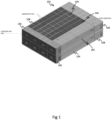
- Figure 1 shows a first embodiment of a laboratory facility 102 fabricated using a modular building construction system.
- the laboratory facility 102 comprises a plurality of primary function modules in the form of laboratory pods 104, two transition modules in the form of corridor pods 106 and two support modules in the form of plant room pods 108.
- the laboratory pods 104 are arranged in pairs, one above the other. Each pair is arranged adjacent another pair of laboratory pods 104. There are 8 laboratory pods 104 in total.
- the two corridor pods 106 are arranged one above the other and are disposed at the ends of the laboratory pods 104 and are configured to allow people, such as laboratory staff, to move between the laboratory pods 104 via the corridor pods 106.
- Each corridor pod 106 defines a corridor or part of a corridor through which persons can move.
- the plant room pods 108 are also arranged one above the other and are disposed at the ends of the laboratory pods 104 opposite the ends at which the corridor pods 106 are disposed.
- the plant room pods 108 are self-contained with easy access at the side of the laboratory facility 102, and can be configured to accommodate plant machinery that supplies selected other pods. This approach can be used to decentralise systems such as ventilation systems which, in turn, can reduce overall energy consumption.
- Each plant room pod 108 provides a room or multiple rooms in which services equipment such as plant machinery, for example a heating, ventilation and air conditioning (HVAC) system, may be located.
- HVAC heating, ventilation and air conditioning
- the facility 102 has a lower first floor (i.e. a ground floor) and an upper second floor, each floor having four laboratory pods 104 connected by a corresponding corridor pod 106, and a plant room pod 108.
- a lower first floor i.e. a ground floor
- an upper second floor each floor having four laboratory pods 104 connected by a corresponding corridor pod 106, and a plant room pod 108.
- Each floor i.e. the upper and lower floors
- Each floor is self-contained in the sense that services are supplied from a plant room pod 108 on the same floor. This allows for floors of the facility 102 to be repurposed and reconfigured with negligible impact on other floors.
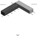
- Figure 2 shows a laboratory pod 104 adjacent a plant room pod 108 of Figure 1 in isolation.
- the laboratory pod 104 comprises four windows 110a, 110b, 110c, 110d and a door 112 at the end that is adjacent the corridor pod 106.
- the plant room pod 108 comprises a door 114.
- each laboratory pod 104 is fabricated from a plurality of beams 116, 118, uprights 120 and panels 122, 124, 126 having standard dimensions. That is to say each beam 116, 118, upright 120 and panel 122, 124, 126 (only one example of each component has been indicated with a reference sign for clarity) has a dimensions, such as length, width and thicknesses, which are not specific to the laboratory pod 104 constructed.
- the panels 122, 124, 126 may be made of a material certified for a clean-room application and may be resistant to vapourised hydrogen peroxide to allow them to be disinfected using vapourised hydrogen peroxide.
- Each laboratory pod 104 provides a laboratory room in which laboratory equipment may be disposed.
- the laboratory pod 104 has a length off 20 metres (m), a width of 5 metres (m) and a height of 4.2 metres (m), and so is configured to a standard size that can be transported using conventional road haulage.
- the laboratory pod 104 is fabricated from twelve uprights 120, five uprights 120 on one side, five uprights 120 on the other side, and one additional upright 120 at each end.
- Longitudinal beams 118 extend along each side, respectively, both top and bottom.
- Lateral beams 116 extend laterally from each side beam to a central longitudinal beam.
- the beams 116, 118 therefore form an open framework having openings between the beams for receiving the panels 122, 124, 126.
- Ceiling panels 122 are provided between the lateral beams 116 and the longitudinal beams 118.
- End panels 124 are provided between the uprights 120 at the ends of the laboratory pod 104.
- the door 112 is provided in the panel 124 on the right hand side as viewed in Figure 3 .
- Windowed panels 126 are provided between the uprights 120 along each side of the laboratory pod 104. Each windowed panel 126 has an elongate window 128 provided in it.
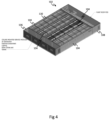
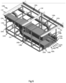
- FIG 4 shows the laboratory facility 102 shown in Figure 1 with the ceiling panels 122 of the laboratory pods 104, corridor pods 106, and plant room pods 108 absent.
- Each laboratory pod 104 is provided with a plurality of ceiling mounted service modules 130.
- a service module 130 is a prefabricated module that may comprise any one or more ventilation ducts, electrical cable trays, lighting connectors, room utilities and piping for delivery of fluids, particularly gases.
- Each service module 130 has a preconfigured arrangement and is configured to occupy a space immediately below a ceiling panel 122 or to occupy a space immediately below a plurality of ceiling panels 122 which corresponds to an exact number of ceiling panels 122.
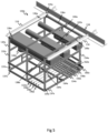
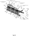
- FIG. 5 shows a first embodiment of a service module 130a.
- the service module 130a comprises a support framework 132a having support uprights 134a and upper and lower support beams 136a, 137a.
- the support beams 136a, 137a extend laterally and are connected to the support uprights 134a to provide structural rigidity.
- the support uprights 134a and upper and lower support beams 136a, 137a may comprise met-strut 41x41 or 82x41 configurations which are assembled by welding the met-struts together.
- Support uprights 134a and upper and lower support beams 136a, 137a may, however, be fabricated for specific loading requirements based on standard British steel sizes which may then be welded or bolted together.
- the upper support beams 136a are configured to be secured to the lateral beams 116 of the laboratory pod 104 such that the service module 130a is suspended below the lateral beams 116.
- the service module 130a has a size and shape which corresponds to the size and shape of ceiling panel 122 and so fits directly under a ceiling panel 122 without protruding laterally from beneath it. This allows service modules 130 to be placed in close proximity to each other under adjacent ceiling panels 122 which, in turn, allows for conveying components such as ventilation ducting, cable trays and piping of adjacent service modules to be connected directly to each other.
- a first air supply ventilation duct 138a is suspended below the upper support beams 136a.
- the first air supplied ventilation duct 138a has a downwardly facing outlet 140a.
- a second air supply ventilation duct 142a is suspended below the upper support beams 136a adjacent the first air supply ventilation duct 138a.
- An air extract ventilation duct 144a is also suspended below the upper support beams 136a adjacent the second air supply ventilation duct 142a.
- each ventilation duct 138a , 142a, 144a is arranged such that they can be connected to ducts of an adjacent service module with which they align.
- each ventilation duct 138a , 142a, 144a comprises a connector at each open end in the form of a flange arrangement that is configured to be directly connected to a corresponding duct of an adjacent service module having a corresponding flange arrangement.
- clamping means such as a G-clamp
- An example of a suitable connector arrangement is a slide-on and crimp flange connector system.
- Each ventilation duct 138a , 142a, 144a may comprise one or more of the following features: straight ducting, bend ducting, such as an elbow for changing the direction in which a duct extends, a reducer, manual and/or automatic dampers (which may be electrically, hydraulically or pneumatically actuated), attenuators, heater batteries, temperature transmitters and gas-tight dampers.
- the ducts may be any suitable configuration including ducts having a rectangular cross-section, circular cross-section, a spiral configuration, or a combination of these depending on requirements. Ducting may also be provided for exhausting specific gases arising from processes.
- Fluid supply pipes comprising an oxygen supply pipe 146a, a nitrogen supply pipe 148a, a compressed air supply pipe 150a, and a carbon dioxide supply pipe 152a are connected to lower support beams 136a such that they extend horizontally.
- the fluid supply pipes 146a, 148a, 150a, 152a are arranged such that they can be directly connected at each of their ends to fluid supply pipes of an adjacent service module with which they align.
- the fluid supply pipes 146a, 148a, 150a, 152a turn through right angles in a horizontal plane as they extend through the service module 130a.
- supply and return pipes for various services and/or pneumatic systems including low-temperature hot water, reverse osmosis, process cooling water, chilled water, boosted cold water, hot water, water for injection, such as high pressure water and/or natural gas.
- Each pipe is provided with a connector arranged to connect to a connector of a corresponding pipe in an adjacent services module.
- a connector may comprise a flange connector, threaded connector, welded connection, coupling connector, ferule and tri-clover TM connector or a press-fit connection depending on requirements and suitability.
- the pipes may also comprise bend sections, such as elbows, for changing the direction in which a pipe extends, reducers, valves and/or inline instrumentation.
- Pipes may be fabricated from suitable materials including stainless steel, such as 304 and 316L, ASME BPE, schedule carbon steel and copper.
- Cable trays 154a, 156a, 158a, 160a, 162a are connected to auxiliary support beams 164a that are situated above the lower support beams 137a and so provide an intermediate level for supporting the cable trays 154a, 156a, 158a, 160a, 162a.
- the cable trays 154a, 156a, 158a, 160a, 162a are arranged to allow electrical cables to be laid along them and can be aligned with cable trays of an adjacent service module having similarly configured cable trays.
- the cable trays 154a, 156a, 158a, 160a, 162a may comprise light, medium and/or heavy-duty cable trays. There may also be provided other cable containment and associated component(s) including ladder rack(s), cable basket(s) and/or cable trunking.
- one or more busbars may be provided to distribute electrical services as an alternative or addition to cables.
- Such services include, low-voltage and high-voltage distribution, data distribution and retrieval, including communication networks, lighting power distribution, Environmental Monitoring System (EMS) distribution and Building Management System (BMS) distribution.
- the busbars are arranged such that they are aligned with at least one respective busbar of an adjacent service module such that the busbars of adjacent service modules can be connected directly to each other by a suitable connector such as a busbar end feed connector.
- Other electrical components that may be supported by the service module include bends/elbows, tee pieces, reducers, joining plates, junction boxes, end feed units, tap off units, junction blocks, distribution boards, remote ethernet IO modules, control panels.
- FIG. 6 shows a second embodiment of a service module 130b.
- the service module 130b is similar to the first embodiment in that it comprises a support framework 132b having support uprights 134b and upper and lower support beams 136b, 137b.
- the support beams 136b, 137b extend laterally and are connected to the support uprights 134b to provide structural rigidity.
- the upper support beams 136b are configured to be secured to the lateral beams 116 of the laboratory pod 104 such that the service module 130b is suspended underneath the lateral beams 116.
- the support beams 136b, 137b are approximately double the length of the support beams of the first embodiment of service module 130a shown in Figure 5 .
- the service module 130b therefore has a size and shape which corresponds to the size and shape of two adjacent ceiling panels 122 and so fits directly under two adjacent ceiling panels 122 without protruding laterally from beneath them.
- a first air supply ventilation duct 138b is suspended below the upper support beams 136b.
- the first air supplied ventilation duct 138a has downwardly facing outlets 140b.
- a second air supply ventilation duct 142b is suspended below the upper support beams 136b adjacent the first air supply ventilation duct 138b.
- An air extract ventilation duct 144b is also suspended below the upper support beams 136a adjacent the second air supply ventilation duct 142b.
- the first air supply ventilation duct 138b extends longitudinally within the service module 130b.
- the second air supply ventilation duct 142b and the air extract ventilation duct 144b are configured to bend within the service module 130b such that the ends of the ducts 142b, 144b are at different height within the service module 130b.
- the ducts 138b, 142b, 144b are arranged such that they can be connected to ducts of an adjacent service module with which they align.
- Fluid supply pipes comprising an oxygen supply pipe 146b, a nitrogen supply pipe 148b, a compressed air supply pipe 150b, and a carbon dioxide supply pipe 152b are connected to lower support beams 136b such that they extend horizontally.
- the fluid supply pipes 146b, 148b, 150b, 152b are arranged such that they can be connected at each of their ends to air supply pipes of an adjacent service module with which they align.
- the fluid supply pipes 146b, 148b, 150b, 152b extend longitudinally within the service module 130b.
- Cable trays 154b, 156b, 158b, 160b, 162b are connected to auxiliary support beams 164b that are situated above the lower support beams 137b.
- the cable trays 154b, 156b, 158b, 160b, 162b are arranged to allow electrical cables along them and can be aligned with cable trays of an adjacent service module having similarly configured cable trays.
- a service module 130 may be configured to a desired specification.
- the service modules may have predefined standard unit widths, lengths and heights. The widths and lengths may vary between service modules, but do so in predefined increments that correspond to a unit width.
- the first embodiment of a service module 130a (shown in Figure 5 ) which occupies the space under a single ceiling panel 122 may be considered to have a single unit width and a single unit length.
- the second embodiment of a service module 130b (shown in Figure 6 ) which occupies the space under two ceiling panels 122 may be considered to have a single unit width and a double unit length.
- Figures 7 , 8 , 9 , 10 and 11 show third, fourth, fifth, sixth and seventh embodiments of a service module 130c, 130d, 130e, 130f, 130g.
- the third embodiment 130c has a unit width and a double unit length.
- the fourth and fifth embodiments 130d, 130e have a single unit width and a unit length.
- the fifth and embodiments 130f, 130g have a single unit width and a quadruple unit length.
- Each embodiment 130c, 130d, 130e, 130f, 130g has components that correspond to at least some of the components of the first and second embodiments 130a, 130b.
- the components take the same reference numbers with the relevant letter for each embodiment.
- the embodiments illustrate how the various components may be arranged in accordance with a specification. For example, cable trays may be arranged two extend perpendicularly with respect to each other or to have bends in them.
- the system provides a means by which ducting, cable, pipes and connectors can be preassembled in modules in accordance with a desired layout whereupon the service modules when connected to a laboratory pod 102 follow a desired layout.
- Multiple service networks can therefore be installed in a predetermined layout by installing the preassembled service modules. This allows for a substantially proportion of the network to be assembled remotely from the building in which it is to be installed and provides a significant reduction in installation time on-site.
- ceiling mounted service modules 130 By providing ceiling mounted service modules 130, ready access is provided to services from above through the ceiling of the laboratory pod 102, such as cables, piping and ducting, which greatly reduces the time taken for installation of services (e.g. traditional first and second 'fix' services) and commissioning.
- services e.g. traditional first and second 'fix' services
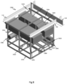
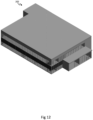
- Figure 12 shows a second embodiment of a laboratory facility 202 fabricated using a modular building construction system.
- the facility 202 is a hybrid arrangement fabricated using a combination of conventional building techniques and a modular building construction system.
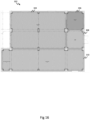
- Figure 13 shows a layout of a first floor (the ground floor) of the laboratory facility 202 shown in Figure 12 .
- the first floor of the laboratory facility 202 comprises three support modules in the form of first, second and third plant room pods 204, 206, 208 which are positioned adjacent a conventional building structure 203.
- the conventional building structure 203 includes an office room 210, which provides office space, a reception space and also a dedicated space preparing food and beverages, each of which may be sub-divisions of the office room 210; a break out room 212, which provides an informal meeting space annexed to the office room 210; a male change room 214, which provides a space for male personnel to change attire; a female change room 216, which provides a space for female personnel to change attire; a water closet room 218, which is subdivided to provide individual toilet cubicles; a computer hardware room 220, which provides a space for accommodating computer hardware; first, second and third meeting room 222, 224 226, which provide private meeting spaces; a conferencing room 228, which provides a conferencing space; a consumables room 230, which provides a storage facility for consumables used in the laboratories such as bottles, carboys, centrifuge tubes, vials slides and petri dishes and which may be transferred to the laboratories as required; a sample delivery room 232, which
- the conventional building structure 203 also includes an entrance room 236, a first stairwell 238 and a second stairwell 240.
- Figure 14 shows a layout of a second floor (an upper floor) of the laboratory facility 202 shown in Figure 12 .
- the second floor of the laboratory facility 202 comprises three support modules in the form of fourth, fifth and sixth plant room pods 242, 244, 246 which are positioned adjacent the building structure 203 and above the first, second and third plant rooms 204, 206, 208.
- the second floor of the conventional building structure 203 includes first, second, third, fourth and fifth laboratory rooms 248, 250, 252, 254, 256.
- Each laboratory room 248, 250, 252, 254, 256 is subdivided into a gowning space and a laboratory space.
- the conventional building structure 203 also comprises a first corridor 258 which extends around the laboratory rooms 248, 250, 252, 254, 256 and also has a portion which extends between the first, second, third and fourth laboratory rooms 248, 250, 252, 254, which are positioned in a line adjacent one another, and the fifth laboratory room 256.
- the corridor 258 is subdivided by three doors 259a, 259b, 259c to form an 'entrance' corridor 258a and an 'exit' corridor 258b.
- the conventional building structure 203 also comprises a third stairwell 260, which is disposed directly above and adjoins the first stairwell 238 to form a single stairwell between the first and second floors, and a second stairwell 262 which is disposed directly above and adjoins the second stairwell 240 to form a single stairwell between the first and second floors.
- Each plant room pod is fabricated using uprights, longitudinal and lateral beams, and panels having standard configurations such as those used in the fabrication of the laboratory pod 104 described with reference to Figure 3 , and is equipped with service modules, as required.
- the plant room pods 204, 206, 208, 242, 244, 246 may be assembled off-site away from the conventional building structure 203 before being transported to the building location and loated in position adacent the conventional building structure 203, as shownin Figures 13 and 14 . Once in position the plant room pods 204, 206, 208, 242, 244, 246 are joined with the conventional building structure and clad with a suitable cladding system that is the same as the cladding system used for the conventional building structure 203 so as to create the appearance of an integrated facility 202.
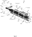
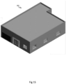
- Figures 15 and 16 show a facility having a single primary function module in the form of a dry room pod 304; two transition modules in the form of an air lock module 306 and a lobby module 308; and a support module in the form of a plant room pod 310.
- Each pod is fabricated using uprights, longitudinal and lateral beams, and panels having standard configurations such as those used in the fabrication of the laboratory pod 104 described with reference to Figure 3 , and is equipped with service modules, as required.
- the modular building construction system may be used for a range of applications including the fabrication of medical, research and manufacturing facilities.
- the modular building construction system may be used to construct vaccine development facilities, cell gene therapy facilities and advanced therapy medicinal product facilities.
- Buildings may use heat recovery, heat pumps and integrated solar panels to reduce or eliminate carbon dioxide emissions.
- the modular building construction system may reduce the amount of space (area) required for a plant room by 50% or more.
Landscapes
- Engineering & Computer Science (AREA)
- Architecture (AREA)
- Civil Engineering (AREA)
- Structural Engineering (AREA)
- Physics & Mathematics (AREA)
- Electromagnetism (AREA)
- Ventilation (AREA)
- Conveying And Assembling Of Building Elements In Situ (AREA)
Applications Claiming Priority (2)
| Application Number | Priority Date | Filing Date | Title |
|---|---|---|---|
| GB2100147.4A GB2602639B (en) | 2021-01-06 | 2021-01-06 | Modular building construction system |
| EP21216454.5A EP4026963B1 (de) | 2021-01-06 | 2021-12-21 | Modulares gebäudebausystem |
Related Parent Applications (1)
| Application Number | Title | Priority Date | Filing Date |
|---|---|---|---|
| EP21216454.5A Division EP4026963B1 (de) | 2021-01-06 | 2021-12-21 | Modulares gebäudebausystem |
Publications (2)
| Publication Number | Publication Date |
|---|---|
| EP4464853A2 true EP4464853A2 (de) | 2024-11-20 |
| EP4464853A3 EP4464853A3 (de) | 2025-02-26 |
Family
ID=74566585
Family Applications (3)
| Application Number | Title | Priority Date | Filing Date |
|---|---|---|---|
| EP24205410.4A Pending EP4467740A3 (de) | 2021-01-06 | 2021-12-21 | Modulares gebäudebausystem |
| EP24205405.4A Pending EP4464853A3 (de) | 2021-01-06 | 2021-12-21 | Modulares gebäudebausystem |
| EP21216454.5A Active EP4026963B1 (de) | 2021-01-06 | 2021-12-21 | Modulares gebäudebausystem |
Family Applications Before (1)
| Application Number | Title | Priority Date | Filing Date |
|---|---|---|---|
| EP24205410.4A Pending EP4467740A3 (de) | 2021-01-06 | 2021-12-21 | Modulares gebäudebausystem |
Family Applications After (1)
| Application Number | Title | Priority Date | Filing Date |
|---|---|---|---|
| EP21216454.5A Active EP4026963B1 (de) | 2021-01-06 | 2021-12-21 | Modulares gebäudebausystem |
Country Status (2)
| Country | Link |
|---|---|
| EP (3) | EP4467740A3 (de) |
| GB (1) | GB2602639B (de) |
Families Citing this family (2)
| Publication number | Priority date | Publication date | Assignee | Title |
|---|---|---|---|---|
| CN115506636B (zh) * | 2021-11-30 | 2025-07-08 | 青岛特锐德电气股份有限公司 | 一种变电站用模块化预制舱及变电站 |
| GB2639017A (en) * | 2024-03-07 | 2025-09-10 | Merit Group Services Ltd | A service network system for an operating theatre |
Family Cites Families (10)
| Publication number | Priority date | Publication date | Assignee | Title |
|---|---|---|---|---|
| KR101075914B1 (ko) * | 2004-12-23 | 2011-10-26 | 재단법인 포항산업과학연구원 | 모듈러 건축물의 모듈간 접합 구조 |
| GB0802416D0 (en) * | 2008-02-08 | 2008-03-19 | Big Steps Ltd | Interconnection modules |
| DK2464913T3 (en) * | 2009-08-16 | 2018-05-22 | G Con Mfg Inc | MODULAR, SELF-STANDARD, MOBILE CLEANING ROOM |
| ES2605598T3 (es) * | 2012-01-23 | 2017-03-15 | Vastint Hospitality B.V. | Panel prefabricado para un edificio |
| ES2642160B1 (es) * | 2016-05-11 | 2018-05-08 | Gabadi, S.L. | Procedimiento de construcción de instalaciones habitables para artefactos flotantes, instalación habitable y contenedor |
| DE102017125886A1 (de) * | 2017-11-06 | 2019-05-09 | Binder Beteiligungs AG | Raumzelle zur Verwendung bei der Errichtung von Gebäuden in Systembauweise |
| US20190277020A1 (en) * | 2018-03-09 | 2019-09-12 | Xtreme Cubes Corporation | System and method for modular building plant oil extraction room |
| FI20185670A1 (en) * | 2018-08-03 | 2020-02-04 | Admares Group Oy | BUILDING |
| CN111561191B (zh) * | 2020-05-14 | 2024-09-03 | 军事科学院系统工程研究院卫勤保障技术研究所 | 一种负压方舱临床检验模块 |
| CN111648477A (zh) * | 2020-05-30 | 2020-09-11 | 江苏上骐重工科技有限公司 | 一种机动模块化多用医疗系统 |
-
2021
- 2021-01-06 GB GB2100147.4A patent/GB2602639B/en active Active
- 2021-12-21 EP EP24205410.4A patent/EP4467740A3/de active Pending
- 2021-12-21 EP EP24205405.4A patent/EP4464853A3/de active Pending
- 2021-12-21 EP EP21216454.5A patent/EP4026963B1/de active Active
Also Published As
| Publication number | Publication date |
|---|---|
| EP4026963A2 (de) | 2022-07-13 |
| GB202100147D0 (en) | 2021-02-17 |
| EP4467740A2 (de) | 2024-11-27 |
| GB2602639B (en) | 2023-04-05 |
| EP4026963A3 (de) | 2022-09-14 |
| EP4467740A3 (de) | 2025-04-23 |
| EP4464853A3 (de) | 2025-02-26 |
| GB2602639A (en) | 2022-07-13 |
| EP4026963B1 (de) | 2024-10-09 |
Similar Documents
| Publication | Publication Date | Title |
|---|---|---|
| EP4026963B1 (de) | Modulares gebäudebausystem | |
| CN105376986B (zh) | 模块化数据中心 | |
| EP2516759B1 (de) | Modulare verarbeitungsanlage | |
| CN108884673A (zh) | 带有集成设备的模块化建筑结构 | |
| KR20170040255A (ko) | 유틸리티를 청정실, 격리 또는 봉쇄 큐비클, 포드 또는 모듈에 공급하는 모듈형 부품 | |
| CN1009845B (zh) | 房间部件特别是船上的小室或住仓 | |
| EP4026964B1 (de) | System zur installation eines servicenetzes | |
| US20240328147A1 (en) | Modular Building Construction System | |
| US20240328148A1 (en) | Modular building construction system | |
| GB2628044A (en) | Modular building construction system | |
| GB2614622A (en) | Modular building construction system | |
| CN212130044U (zh) | 油气田及管道管控式电、控、信集成小屋 | |
| CN111021785A (zh) | 一种便捷拆装的箱式房及其安装方法 | |
| EP3577289A1 (de) | Modulare verarbeitungsanlage mit verteilten kühlsystemen | |
| US20250101759A1 (en) | Modular Building Construction System | |
| CN119998971A (zh) | 用于集成多个燃料电池模块的设备和方法 | |
| CN204254734U (zh) | 锅炉设备系统及其组成和结构元件 | |
| US20250283618A1 (en) | Service Network System for an Operating Theatre | |
| WO2019089694A1 (en) | Cracker modular processing facility | |
| JP7202089B2 (ja) | 配線設計支援システム | |
| KR102894128B1 (ko) | 모듈러의 설비 연결 구조 및 이를 이용한 모듈러의 시공방법 | |
| CN223309422U (zh) | 一种模块化分段式预制舱 | |
| CN221823505U (zh) | 机房和数据中心 | |
| US20260005281A1 (en) | Apparatus and method for integrating a plurality of fuel cell modules | |
| US20250146277A1 (en) | Wall panels and other components for custom enclosures for shipping containers, mobile units and other dwellings |
Legal Events
| Date | Code | Title | Description |
|---|---|---|---|
| PUAI | Public reference made under article 153(3) epc to a published international application that has entered the european phase |
Free format text: ORIGINAL CODE: 0009012 |
|
| STAA | Information on the status of an ep patent application or granted ep patent |
Free format text: STATUS: THE APPLICATION HAS BEEN PUBLISHED |
|
| AC | Divisional application: reference to earlier application |
Ref document number: 4026963 Country of ref document: EP Kind code of ref document: P |
|
| AK | Designated contracting states |
Kind code of ref document: A2 Designated state(s): AL AT BE BG CH CY CZ DE DK EE ES FI FR GB GR HR HU IE IS IT LI LT LU LV MC MK MT NL NO PL PT RO RS SE SI SK SM TR |
|
| REG | Reference to a national code |
Ref country code: DE Ref legal event code: R079 Free format text: PREVIOUS MAIN CLASS: E04B0001348000 Ipc: E04H0001000000 |
|
| PUAL | Search report despatched |
Free format text: ORIGINAL CODE: 0009013 |
|
| AK | Designated contracting states |
Kind code of ref document: A3 Designated state(s): AL AT BE BG CH CY CZ DE DK EE ES FI FR GB GR HR HU IE IS IT LI LT LU LV MC MK MT NL NO PL PT RO RS SE SI SK SM TR |
|
| RIC1 | Information provided on ipc code assigned before grant |
Ipc: E04B 1/348 20060101ALI20250122BHEP Ipc: E04H 1/00 20060101AFI20250122BHEP |
|
| STAA | Information on the status of an ep patent application or granted ep patent |
Free format text: STATUS: REQUEST FOR EXAMINATION WAS MADE |
|
| 17P | Request for examination filed |
Effective date: 20250821 |