EP4464833A1 - Vorrichtung zur behandlung von kleidungsstücken - Google Patents
Vorrichtung zur behandlung von kleidungsstücken Download PDFInfo
- Publication number
- EP4464833A1 EP4464833A1 EP23839768.1A EP23839768A EP4464833A1 EP 4464833 A1 EP4464833 A1 EP 4464833A1 EP 23839768 A EP23839768 A EP 23839768A EP 4464833 A1 EP4464833 A1 EP 4464833A1
- Authority
- EP
- European Patent Office
- Prior art keywords
- piston
- bobbin
- friction member
- radial
- treating apparatus
- Prior art date
- Legal status (The legal status is an assumption and is not a legal conclusion. Google has not performed a legal analysis and makes no representation as to the accuracy of the status listed.)
- Pending
Links
Images


Classifications
-
- D—TEXTILES; PAPER
- D06—TREATMENT OF TEXTILES OR THE LIKE; LAUNDERING; FLEXIBLE MATERIALS NOT OTHERWISE PROVIDED FOR
- D06F—LAUNDERING, DRYING, IRONING, PRESSING OR FOLDING TEXTILE ARTICLES
- D06F37/00—Details specific to washing machines covered by groups D06F21/00 - D06F25/00
- D06F37/20—Mountings, e.g. resilient mountings, for the rotary receptacle, motor, tub or casing; Preventing or damping vibrations
- D06F37/22—Mountings, e.g. resilient mountings, for the rotary receptacle, motor, tub or casing; Preventing or damping vibrations in machines with a receptacle rotating or oscillating about a horizontal axis
- D06F37/225—Damping vibrations by displacing, supplying or ejecting a material, e.g. liquid, into or from counterbalancing pockets
-
- D—TEXTILES; PAPER
- D06—TREATMENT OF TEXTILES OR THE LIKE; LAUNDERING; FLEXIBLE MATERIALS NOT OTHERWISE PROVIDED FOR
- D06F—LAUNDERING, DRYING, IRONING, PRESSING OR FOLDING TEXTILE ARTICLES
- D06F39/00—Details of washing machines not specific to a single type of machines covered by groups D06F9/00 - D06F27/00
- D06F39/12—Casings; Tubs
- D06F39/125—Supporting arrangements for the casing, e.g. rollers or legs
-
- F—MECHANICAL ENGINEERING; LIGHTING; HEATING; WEAPONS; BLASTING
- F16—ENGINEERING ELEMENTS AND UNITS; GENERAL MEASURES FOR PRODUCING AND MAINTAINING EFFECTIVE FUNCTIONING OF MACHINES OR INSTALLATIONS; THERMAL INSULATION IN GENERAL
- F16F—SPRINGS; SHOCK-ABSORBERS; MEANS FOR DAMPING VIBRATION
- F16F7/00—Vibration-dampers; Shock-absorbers
- F16F7/08—Vibration-dampers; Shock-absorbers with friction surfaces rectilinearly movable along each other
- F16F7/09—Vibration-dampers; Shock-absorbers with friction surfaces rectilinearly movable along each other in dampers of the cylinder-and-piston type
-
- F—MECHANICAL ENGINEERING; LIGHTING; HEATING; WEAPONS; BLASTING
- F16—ENGINEERING ELEMENTS AND UNITS; GENERAL MEASURES FOR PRODUCING AND MAINTAINING EFFECTIVE FUNCTIONING OF MACHINES OR INSTALLATIONS; THERMAL INSULATION IN GENERAL
- F16F—SPRINGS; SHOCK-ABSORBERS; MEANS FOR DAMPING VIBRATION
- F16F9/00—Springs, vibration-dampers, shock-absorbers, or similarly-constructed movement-dampers using a fluid or the equivalent as damping medium
- F16F9/10—Springs, vibration-dampers, shock-absorbers, or similarly-constructed movement-dampers using a fluid or the equivalent as damping medium using liquid only; using a fluid of which the nature is immaterial
- F16F9/14—Devices with one or more members, e.g. pistons, vanes, moving to and fro in chambers and using throttling effect
-
- F—MECHANICAL ENGINEERING; LIGHTING; HEATING; WEAPONS; BLASTING
- F16—ENGINEERING ELEMENTS AND UNITS; GENERAL MEASURES FOR PRODUCING AND MAINTAINING EFFECTIVE FUNCTIONING OF MACHINES OR INSTALLATIONS; THERMAL INSULATION IN GENERAL
- F16F—SPRINGS; SHOCK-ABSORBERS; MEANS FOR DAMPING VIBRATION
- F16F9/00—Springs, vibration-dampers, shock-absorbers, or similarly-constructed movement-dampers using a fluid or the equivalent as damping medium
- F16F9/32—Details
- F16F9/53—Means for adjusting damping characteristics by varying fluid viscosity, e.g. electromagnetically
- F16F9/535—Magnetorheological [MR] fluid dampers
-
- D—TEXTILES; PAPER
- D06—TREATMENT OF TEXTILES OR THE LIKE; LAUNDERING; FLEXIBLE MATERIALS NOT OTHERWISE PROVIDED FOR
- D06F—LAUNDERING, DRYING, IRONING, PRESSING OR FOLDING TEXTILE ARTICLES
- D06F39/00—Details of washing machines not specific to a single type of machines covered by groups D06F9/00 - D06F27/00
- D06F39/12—Casings; Tubs
-
- F—MECHANICAL ENGINEERING; LIGHTING; HEATING; WEAPONS; BLASTING
- F16—ENGINEERING ELEMENTS AND UNITS; GENERAL MEASURES FOR PRODUCING AND MAINTAINING EFFECTIVE FUNCTIONING OF MACHINES OR INSTALLATIONS; THERMAL INSULATION IN GENERAL
- F16F—SPRINGS; SHOCK-ABSORBERS; MEANS FOR DAMPING VIBRATION
- F16F2222/00—Special physical effects, e.g. nature of damping effects
- F16F2222/04—Friction
Definitions
- the present disclosure relates to a clothes treating apparatus, and more particularly, to a clothes treating apparatus including an improved damper.
- clothes treating apparatuses include a washing machine for washing clothes put into the drum through friction by rotating the clothes together with a detergent by using a driving force of the motor, and a dryer for drying objects to be dried by rotating the drum in which the objects are accommodated.
- the cylinder may include a radial protrusion protruding from an inner surface of the bobbin forming the inside space to accommodate the friction member.
- the bobbin may further include: a support plate extending in a radial direction of the bobbin to be in contact with the yoke; and an extension portion extending from the support plate along a longitudinal direction of the piston, wherein a radius length of the extension portion is smaller than a radius length of the support plate, and the damper may further include a coil configured to surround an outer circumference of the extension portion and interwork with the friction member including the magneto-rheological fluid.
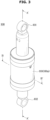
- FIG. 1 is a perspective view of a clothes treating apparatus according to an embodiment of the disclosure.
- FIG. 2 is a perspective view showing some components of the clothes treating apparatus shown in FIG. 1 .
- a clothes treating apparatus 1 may include a washing machine 1.
- the washing machine 1 may include a cabinet 10 forming an appearance, a tub 12 installed inside the cabinet 10 and storing washing water, and a drum 11 rotatably installed inside the tub 12 and being in the shape of a cylinder, wherein a plurality of dehydrating holes may be formed in a wall of the tub 12.
- a door 20 for opening or closing the openings of the tub 12 and the drum 11 may be mounted.
- the piston 120 may extend in one direction.
- the piston 120 may be movable inside the cylinder 100a.
- the piston 120 may be referred to as a rod 120.
- vibrations of the tub 12 may be damped by friction between the piston 120 and the cylinder 100a, which is generated by the piston 120 moving back and forth in an inside space 100b of the cylinder 100a.
- the second fixing portion 102 may be provided at one end of the piston 120.
- the second fixing portion 102 may be formed at one end of the piston 120, which is not inserted in the inside space 100b of the cylinder 100a.
- the second fixing portion 102 may be fixed to the bottom plate 10d, although not limited thereto. However, the second fixing portion 102 may be fixed to the tub 12.
- first case 111, the second case 112, the third case 113, the fourth case 114, the fifth case 115, and the sixth case 116 are shown to be separate components, however, the first case 111, the second case 112, the third case 113, the fourth case 114, the fifth case 115, and the sixth case 116 may be integrated into one body.
- the first case 111 may be positioned at one end of the cylinder case 110.
- the first case 111 may be coupled to the second case 112.
- the first fixing portion 101 may be formed at one end of the first case 111.
- the first case 111 may accommodate a portion of the piston 120 therein.
- the third case 113 may be coupled to the second case 112 and the fourth case 114.
- the third case 113 may cover a portion of the piston 120, and accommodate a sealing member 170.
- the piston 120 may penetrate the cavity 113a of the third case 113.
- the cylinder 100a may further include the yoke 130 and the bobbin 140.
- the yoke 130 may have a cavity forming the inside space 100b of the cylinder 100a.
- the yoke 130 may include a cavity 133.
- the cavity 133 may be formed by an inner surface 131.
- the cavity 133 may be referred to as an inside space 133 of the yoke 130.
- the inside space 100b of the cylinder 100a may include the cavity 133 of the yoke 130.
- the piston 120 may be accommodated and/or inserted in the cavity 133.
- a plurality of yokes 130 may be provided.
- the plurality of yokes 130 may include a first yoke 130a, a second yoke 130b, a third yoke 130c, and a fourth yoke 130d.
- the bobbin 140 may be positioned between the plurality of yokes 130.
- a first bobbin 140a may be positioned between the first yoke 130a and the second yoke 130b
- a second bobbin 140b may be positioned between the second yoke 130b and the third yoke 130c
- a third bobbin 140c may be positioned between the third yoke 130c and the fourth yoke 130d.
- the yoke 130 may further include a coil guide 132 and a coupling protrusion (not shown).
- the coil guide 132 may guide the coil 150 that is wound on the bobbin 140.
- the coil guide 132 may be depressed inward along a radial direction of the yoke 130 and/or the cylinder 100a from an outer circumferential surface of the yoke 130.
- the coupling protrusion may couple the yoke 130 to the bobbin 140.
- the bobbin 130 may be coupled to the yoke 130 by a coupling portion formed in the bobbin 140 and the coupling protrusion formed in the yoke 130.
- the coil guide 132 is shown to be positioned only in the second yoke 130b and the third yoke 130c. However, a location of the coil guide 132 is not limited to this. Also, the coil guide 132 and the coupling protrusion may be selective components. For example, the coil guide 132 and the coupling protrusion may be omitted.
- the bobbin 140 may be positioned between the plurality of yokes 130 to space the plurality of yokes 130 from each other.
- the coil 150 may be wound on the bobbin 140.
- the coil 150 may be wound on an extension portion 147 of the bobbin 140 (see FIG. 6 ).
- the bobbin 140 may be a nonmagnetic body.
- the bobbin 140 may be a plastic injection mold.
- the bobbin 140 may have a cavity to form the inside space 100b of the cylinder 100a.
- the bobbin 140 may include a cavity 145.
- the cavity 145 may be formed by an inner surface 141.
- the cavity 145 may be referred to as an inside space 145 of the bobbin 140.
- the inside space 100b of the cylinder 100a may include the cavity 145 of the bobbin 140.
- the piston 120 may be accommodated and/or inserted in the cavity 145.
- a plurality of bobbins 140 may be provided.
- the plurality of bobbins 140 may include a first bobbin 140a, a second bobbin 140b, and a third bobbin 140c.
- the plurality of bobbins 140 may be respectively positioned between the plurality of yokes 130.
- the bobbin 140 may further include a coil guide 144.
- the coil guide 144 may guide the coil 150 that is wound on an outer circumference of the extension portion 147.
- the coil guide 144 may be depressed inward along a radial direction of the bobbin 140 and/or the cylinder 100a from an outer circumferential surface of the support plate 146 (see FIG. 6 ).
- the radial protrusion 142, the coil guide 144, and the coupling portion may be selective components.
- the radial protrusion 142, the coil guide 144, and the coupling portion may be omitted.
- the friction member 160 may include a magneto-rheological fluid. Details about this will be described below.
- FIG. 6 is a cross-sectional view of the damper shown in FIG. 3 .
- FIG. 7 is a cross-sectional view of the damper shown in FIG. 3 .
- the extension portion 147 may be positioned between the plurality of support plates 146.
- the extension portion 147 may be positioned between the first support plate 146a and the second support plate 146b to extend along the longitudinal direction (and/or the extension direction) of the piston 120.
- a radius R2 of the extension portion 147 may be smaller than a radius R1 of the support plate 146.
- the extension portion 147 may connect center portions of the plurality of support plates 146 to each other.
- the coil 150 may be wound on the circumferential surface of the extension portion 147.
- the radial protrusion 142 may protrude from the inner surface 141 of the bobbin 140 toward the piston 120.
- the radial protrusion 142 may protrude from the inner surface 141 of the bobbin 140 toward the cavity 145 along the radial direction of the bobbin 140.
- a plurality of radial protrusions 142 may be provided.
- the plurality of radial protrusions 142 may protrude in a direction of facing each other, although not limited thereto. However, the plurality of radial protrusions 142 may protrude without facing each other.
- the coil 150 may surround an outer circumference of the bobbin 140.
- the coil 150 may surround the extension portion 147.
- the coil 150 may be positioned between the plurality of support plates 146. According to application of current to the coil 150, a magnetic field may be formed, and viscosity and a friction force of the friction member 160 including the magneto-rheological fluid may change.
- a magnetic field By current flowing through the coil 150 wound on the bobbin 140, a magnetic field may be generated, and viscosity of the magneto-rheological fluid may change by the magnetic field.
- current may be applied to the coil 150 to increase viscosity of the magneto-rheological fluid, and accordingly, a friction force applied to the friction member 160 may increase.
- no current may be applied to the coil 150 to decrease viscosity of the magneto-rheological fluid, and accordingly, a friction force applied to the friction member 160 may decrease.
- viscosity of the magneto-rheological fluid changes in an area where a magnetic field is formed by the coil 150
- the viscosity of the magneto-rheological fluid may not change in an area where no magnetic field is formed, which may have no influence on a change of a friction force. Accordingly, a large portion of the friction member 160 including a magneto-rheological fluid may be positioned in an area where a magnetic field is formed, and a small portion of the friction member 160 including a magneto-rheological fluid may be positioned in an area where no magnetic field is formed.
- the friction member 160 may be positioned between the protrusion surface 142a and the outer surface 121 of the piston 120 and/or between the inner surface 141 of the bobbin 140 and the outer surface 121 of the piston 120.
- a portion of the friction member 160 may be positioned between the protrusion surface 142a and the outer surface 121 of the piston 120, and another portion of the friction member 160 may be positioned between the inner surface 141 of the bobbin 140 and the outer surface 121 of the piston 120.
- a magnetic field may be mostly generated between the yoke 130 and the piston 120.
- a small portion of the friction member 160 including the magneto-rheological fluid may be positioned in an area between the bobbin 140 and the piston 120, corresponding to an area where no magnetic field is formed or a small magnetic field is formed.
- a portion of the friction member 160 positioned between the protrusion surface 142a and the outer surface 121 of the piston 120 may be smaller than another portion of the friction member 160 positioned between the inner surface 141 of the bobbin 140 and the outer surface 121 of the piston 120.
- a ratio of a length and/or a thickness between the protrusion surface 142a and the outer surface 121 of the piston 120 and a length and/or a thickness between the inner surface 141 of the bobbin 140 and the outer surface 121 of the piston 120 may be 1 :2.4. However, the ratio is not limited.
- the magneto-rheological fluid has a high cost, a production cost and/or a manufacturing cost of the damper 100 may be reduced, resulting in a reduction of a production cost and/or a manufacturing cost of the clothes treating apparatus 1.
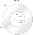
- a plurality of radial protrusions 122 may be provided.
- the plurality of radial protrusions 122 may protrude in opposite directions, although not limited thereto.
- a portion of the friction member 160 positioned between the protrusion surface 122a and the inner surface 141 of the bobbin 140 may be smaller than another portion of the friction member 160 positioned between the inner surface 141 of the bobbin 140 and the outer surface 121 of the piston 120.
- a length and/or a thickness between the protrusion surface 122a and the inner surface 141 of the bobbin 140 may be smaller than a length and/or a thickness between the inner surface 141 of the bobbin 140 and the outer surface 121 of the piston 120.
- FIG. 9 is a cross-sectional view of a damper in a clothes treating apparatus according to an embodiment of the disclosure.
Landscapes
- Engineering & Computer Science (AREA)
- General Engineering & Computer Science (AREA)
- Mechanical Engineering (AREA)
- Physics & Mathematics (AREA)
- Electromagnetism (AREA)
- Textile Engineering (AREA)
- Main Body Construction Of Washing Machines And Laundry Dryers (AREA)
- Fluid-Damping Devices (AREA)
Applications Claiming Priority (2)
| Application Number | Priority Date | Filing Date | Title |
|---|---|---|---|
| KR1020220086558A KR20240009281A (ko) | 2022-07-13 | 2022-07-13 | 의류처리장치 |
| PCT/KR2023/006149 WO2024014674A1 (ko) | 2022-07-13 | 2023-05-04 | 의류처리장치 |
Publications (2)
| Publication Number | Publication Date |
|---|---|
| EP4464833A1 true EP4464833A1 (de) | 2024-11-20 |
| EP4464833A4 EP4464833A4 (de) | 2025-06-25 |
Family
ID=89510617
Family Applications (1)
| Application Number | Title | Priority Date | Filing Date |
|---|---|---|---|
| EP23839768.1A Pending EP4464833A4 (de) | 2022-07-13 | 2023-05-04 | Vorrichtung zur behandlung von kleidungsstücken |
Country Status (3)
| Country | Link |
|---|---|
| US (1) | US12503803B2 (de) |
| EP (1) | EP4464833A4 (de) |
| CN (1) | CN119053742A (de) |
Family Cites Families (25)
| Publication number | Priority date | Publication date | Assignee | Title |
|---|---|---|---|---|
| US6279700B1 (en) | 1999-09-13 | 2001-08-28 | Delphi Technologies, Inc. | Magnetorheological fluid damper |
| JP2006057766A (ja) | 2004-08-20 | 2006-03-02 | Showa Corp | Mr流体ダンパ |
| US20060213289A1 (en) | 2005-03-24 | 2006-09-28 | Kjoller Kevin J | Probe for a scanning probe microscope and method of manufacture |
| JP5127740B2 (ja) | 2009-02-13 | 2013-01-23 | 株式会社東芝 | 洗濯機 |
| KR101197309B1 (ko) | 2009-08-18 | 2012-11-05 | 주식회사 썬 프레인 코 | 자기식 댐퍼 및 이를 구비한 세탁기 |
| JP5349201B2 (ja) | 2009-08-20 | 2013-11-20 | 株式会社東芝 | ドラム式洗濯機 |
| EP2540898B1 (de) * | 2010-02-24 | 2015-08-05 | Kabushiki Kaisha Toshiba | Dämpfer, waschmaschine und wascher/trockner |
| JP5127873B2 (ja) * | 2010-04-26 | 2013-01-23 | 株式会社東芝 | ドラム式洗濯機 |
| JP5127879B2 (ja) | 2010-05-21 | 2013-01-23 | 株式会社東芝 | 洗濯機用のダンパ |
| JP5330345B2 (ja) | 2010-09-17 | 2013-10-30 | 株式会社東芝 | 洗濯機 |
| KR101219177B1 (ko) | 2011-04-29 | 2013-01-09 | 한국과학기술원 | 가변 감쇠 형 진동 저감 장치 |
| JP5738678B2 (ja) * | 2011-06-01 | 2015-06-24 | 株式会社東芝 | 洗濯機 |
| KR20130002114A (ko) | 2011-06-28 | 2013-01-07 | 엘지전자 주식회사 | 세탁기용 댐퍼 |
| JP5773805B2 (ja) * | 2011-08-30 | 2015-09-02 | 株式会社東芝 | 洗濯機 |
| KR200459493Y1 (ko) | 2011-11-15 | 2012-04-02 | 주식회사 삼코 | 경사면 코어를 가지는 드럼 세탁기용 엠알 마찰 댐퍼 |
| KR101285186B1 (ko) | 2011-12-23 | 2013-07-10 | 주식회사 썬 프레인 코 | 엠알유체댐퍼용 요크 |
| JP6042138B2 (ja) | 2012-08-31 | 2016-12-14 | 東芝ライフスタイル株式会社 | 洗濯機用のダンパ |
| CN104278484B (zh) * | 2013-07-10 | 2016-10-12 | 东芝生活电器株式会社 | 洗衣机 |
| KR101472011B1 (ko) | 2013-07-31 | 2014-12-11 | 알엠에스테크놀러지(주) | 미세진동 및 대형구조물의 진동제어에 사용가능한 다용도 mr 댐퍼 |
| KR101757435B1 (ko) | 2016-07-07 | 2017-07-12 | 인하대학교 산학협력단 | 세탁기 진동 저감 메커니즘 |
| KR101757434B1 (ko) | 2016-07-07 | 2017-07-12 | 인하대학교 산학협력단 | 세탁기 진동 저감 메커니즘 |
| KR101984633B1 (ko) | 2018-01-18 | 2019-05-31 | 인하대학교 산학협력단 | Mr 댐퍼 |
| KR102098882B1 (ko) | 2018-07-16 | 2020-04-08 | 인하대학교 산학협력단 | 세탁기의 진동·소음 저감 메커니즘 |
| KR102244520B1 (ko) | 2019-09-11 | 2021-04-27 | 주식회사 루브캠코리아 | Mr 유체 댐퍼 |
| KR102290868B1 (ko) | 2020-03-03 | 2021-08-20 | 피에이치에이 주식회사 | Mr댐퍼를 이용한 오토 도어클로저 |
-
2023
- 2023-05-04 CN CN202380034713.7A patent/CN119053742A/zh active Pending
- 2023-05-04 EP EP23839768.1A patent/EP4464833A4/de active Pending
- 2023-06-14 US US18/209,870 patent/US12503803B2/en active Active
Also Published As
| Publication number | Publication date |
|---|---|
| EP4464833A4 (de) | 2025-06-25 |
| CN119053742A (zh) | 2024-11-29 |
| US20240018712A1 (en) | 2024-01-18 |
| US12503803B2 (en) | 2025-12-23 |
Similar Documents
| Publication | Publication Date | Title |
|---|---|---|
| CN102428224B (zh) | 洗衣机 | |
| US7310978B2 (en) | Drum-type washing machine with elastic oil damper | |
| US9790631B2 (en) | Balancer and washing machine having the same | |
| EP1770199B1 (de) | Lagergehäusevorrichtung für Trommelwaschmaschine und Trommelwaschmaschine mit derselben | |
| KR102909666B1 (ko) | 세탁기 및 이에 구비되는 진동 저감 장치 | |
| US9903066B2 (en) | Washing machine | |
| US10501881B2 (en) | Damping device and washing machine including the same | |
| US20060191301A1 (en) | Mechanism for mounting motor of washing machine and washing machine using the same | |
| CN109972361B (zh) | 衣物处理设备 | |
| US20110094270A1 (en) | Washing machine and balancer thereof | |
| US10697101B2 (en) | Motor for washing machine and washing machine having the same | |
| EP4464833A1 (de) | Vorrichtung zur behandlung von kleidungsstücken | |
| KR102351658B1 (ko) | 세탁기 | |
| KR100591332B1 (ko) | 세탁기의 완충장치 | |
| US10815601B2 (en) | Laundry treatment apparatus | |
| US20250084580A1 (en) | Clothing treatment apparatus and damper for washing machine | |
| KR20240009281A (ko) | 의류처리장치 | |
| CN111593528B (zh) | 衣物处理装置及其控制方法 | |
| US9765466B2 (en) | Balancer and washing machine having the same | |
| US20130269396A1 (en) | Washing machine having damping apparatus | |
| EP2772579B1 (de) | Waschmaschine | |
| KR20200109739A (ko) | 모터 및 그를 가지는 세탁기 | |
| EP2848725B1 (de) | Auswuchtvorrichtung für eine Waschmaschine | |
| KR20140050483A (ko) | 밸런서 및 이를 구비하는 세탁기 | |
| KR20040084134A (ko) | 드럼세탁기의 댐퍼 어셈블리 |
Legal Events
| Date | Code | Title | Description |
|---|---|---|---|
| STAA | Information on the status of an ep patent application or granted ep patent |
Free format text: STATUS: THE INTERNATIONAL PUBLICATION HAS BEEN MADE |
|
| PUAI | Public reference made under article 153(3) epc to a published international application that has entered the european phase |
Free format text: ORIGINAL CODE: 0009012 |
|
| STAA | Information on the status of an ep patent application or granted ep patent |
Free format text: STATUS: REQUEST FOR EXAMINATION WAS MADE |
|
| 17P | Request for examination filed |
Effective date: 20240815 |
|
| AK | Designated contracting states |
Kind code of ref document: A1 Designated state(s): AL AT BE BG CH CY CZ DE DK EE ES FI FR GB GR HR HU IE IS IT LI LT LU LV MC ME MK MT NL NO PL PT RO RS SE SI SK SM TR |
|
| A4 | Supplementary search report drawn up and despatched |
Effective date: 20250522 |
|
| RIC1 | Information provided on ipc code assigned before grant |
Ipc: F16F 7/09 20060101ALI20250516BHEP Ipc: D06F 39/12 20060101ALI20250516BHEP Ipc: F16F 9/53 20060101ALI20250516BHEP Ipc: D06F 37/22 20060101AFI20250516BHEP |
|
| DAV | Request for validation of the european patent (deleted) | ||
| DAX | Request for extension of the european patent (deleted) |