EP4464458A1 - Machine-outil pour la fabrication d'une pièce dotée d'un contour extérieur et procédé correspondant - Google Patents
Machine-outil pour la fabrication d'une pièce dotée d'un contour extérieur et procédé correspondant Download PDFInfo
- Publication number
- EP4464458A1 EP4464458A1 EP23173492.2A EP23173492A EP4464458A1 EP 4464458 A1 EP4464458 A1 EP 4464458A1 EP 23173492 A EP23173492 A EP 23173492A EP 4464458 A1 EP4464458 A1 EP 4464458A1
- Authority
- EP
- European Patent Office
- Prior art keywords
- workpiece
- machine tool
- slide
- tool
- support surface
- Prior art date
- Legal status (The legal status is an assumption and is not a legal conclusion. Google has not performed a legal analysis and makes no representation as to the accuracy of the status listed.)
- Pending
Links
Images
Classifications
-
- B—PERFORMING OPERATIONS; TRANSPORTING
- B23—MACHINE TOOLS; METAL-WORKING NOT OTHERWISE PROVIDED FOR
- B23B—TURNING; BORING
- B23B5/00—Turning-machines or devices specially adapted for particular work; Accessories specially adapted therefor
- B23B5/36—Turning-machines or devices specially adapted for particular work; Accessories specially adapted therefor for turning specially-shaped surfaces by making use of relative movement of the tool and work produced by geometrical mechanisms, i.e. forming-lathes
- B23B5/46—Turning-machines or devices specially adapted for particular work; Accessories specially adapted therefor for turning specially-shaped surfaces by making use of relative movement of the tool and work produced by geometrical mechanisms, i.e. forming-lathes for turning helical or spiral surfaces
- B23B5/48—Turning-machines or devices specially adapted for particular work; Accessories specially adapted therefor for turning specially-shaped surfaces by making use of relative movement of the tool and work produced by geometrical mechanisms, i.e. forming-lathes for turning helical or spiral surfaces for cutting grooves, e.g. oil grooves of helicoidal shape
-
- B—PERFORMING OPERATIONS; TRANSPORTING
- B23—MACHINE TOOLS; METAL-WORKING NOT OTHERWISE PROVIDED FOR
- B23B—TURNING; BORING
- B23B25/00—Accessories or auxiliary equipment for turning-machines
-
- B—PERFORMING OPERATIONS; TRANSPORTING
- B23—MACHINE TOOLS; METAL-WORKING NOT OTHERWISE PROVIDED FOR
- B23B—TURNING; BORING
- B23B3/00—General-purpose turning-machines or devices, e.g. centre lathes with feed rod and lead screw; Sets of turning-machines
- B23B3/06—Turning-machines or devices characterised only by the special arrangement of constructional units
- B23B3/065—Arrangements for performing other machining operations, e.g. milling, drilling
-
- B—PERFORMING OPERATIONS; TRANSPORTING
- B23—MACHINE TOOLS; METAL-WORKING NOT OTHERWISE PROVIDED FOR
- B23C—MILLING
- B23C3/00—Milling particular work; Special milling operations; Machines therefor
- B23C3/16—Working surfaces curved in two directions
-
- B—PERFORMING OPERATIONS; TRANSPORTING
- B23—MACHINE TOOLS; METAL-WORKING NOT OTHERWISE PROVIDED FOR
- B23F—MAKING GEARS OR TOOTHED RACKS
- B23F15/00—Methods or machines for making gear wheels of special kinds not covered by groups B23F7/00 - B23F13/00
- B23F15/08—Making intermeshing rotors, e.g. of pumps
-
- B—PERFORMING OPERATIONS; TRANSPORTING
- B23—MACHINE TOOLS; METAL-WORKING NOT OTHERWISE PROVIDED FOR
- B23Q—DETAILS, COMPONENTS, OR ACCESSORIES FOR MACHINE TOOLS, e.g. ARRANGEMENTS FOR COPYING OR CONTROLLING; MACHINE TOOLS IN GENERAL CHARACTERISED BY THE CONSTRUCTION OF PARTICULAR DETAILS OR COMPONENTS; COMBINATIONS OR ASSOCIATIONS OF METAL-WORKING MACHINES, NOT DIRECTED TO A PARTICULAR RESULT
- B23Q1/00—Members which are comprised in the general build-up of a form of machine, particularly relatively large fixed members
- B23Q1/72—Auxiliary arrangements; Interconnections between auxiliary tables and movable machine elements
- B23Q1/76—Steadies; Rests
- B23Q1/766—Steadies or rests moving together with the tool support
Definitions
- the invention relates to a machine tool for producing a workpiece with an outer contour, in particular a rotor of a screw compressor, and a method therefor.
- the invention therefore has the object of improving a method of the type described above in terms of cycle time, without thereby reducing the reproducibility in terms of manufacturing accuracy.
- the invention solves the problem by the features of claim 1.
- first and a second support surface in particular a sliding surface, of a support device, whereby at least these two support surfaces are arranged at an angle offset from one another around the axis of rotation, deflections can initially be prevented even in the case of comparatively heavy workpieces, for example due to the workpiece weight or Machining forces, an exact positioning is ensured and thus an external contour is produced in a reproducible manner.
- the first and/or the second support surface is adjusted to the workpiece via at least one, in particular linear, guided slide that is provided on a Z-slide of the machine tool.
- the respective support surface can be moved and adjusted comparatively quickly and with precise positioning via the slide system.
- the method according to the invention therefore enables short cycle times with high manufacturing accuracy, which significantly improves the reproducibility of the method.
- the second support surface is positioned via a second slide, which is guided on the first slide. This positioning of the second support surface can take place, for example, in the Y direction of the machine tool.
- the longitudinal directions of the first and/or second support surface run essentially in the Z direction of the machine tool in order to further increase the accuracy of the process. This can be particularly advantageous for workpieces with a cylindrical outer envelope contour.
- the first and/or second support surface is guided towards the workpiece in a radial direction. This further simplifies the handling of the process. In addition, a radial adjustment can lead to stable support of the workpiece in a relatively reproducible manner.
- the supported workpiece is machined while rotating about the axis of rotation, which in particular runs centrally through the workpiece, in order to be able to further reduce the cycle time.
- the method according to the invention can be distinguished for the rapid production of workpieces with mutually different outer contours.
- the support device has two second support surfaces, each of which supports one of the workpieces, wherein the second support surfaces are arranged on opposite outer sides of the second carriage. This is particularly advantageous in the case of two rotors of a double-screw compressor with different outer contours.
- the support according to the invention can also be part of a complete machining process in which, before the workpiece is supported, a pre-machining of the workpiece takes place, in which the outer contour is introduced with allowance using two turning tools that are located opposite one another on the workpiece, in particular diametrically opposite one another. This can further reduce the cycle time in the production of workpieces with precise dimensions.
- the invention also aims to modify the design of a machine tool in such a way that an external contour can be quickly created on a workpiece in a reproducible manner with a high degree of accuracy.
- the machine tool should be characterized by structural simplicity and robustness.
- the invention solves the problem by claim 8.
- the workpiece can be machined more precisely and stably.
- the support device has a first and a second support surface, in particular a sliding surface, which are arranged at an angle offset from one another around the axis of rotation.
- the Z-slide also has at least one, in particular linearly guided, slide on which the first and/or second support surface is provided, this support device can be positioned precisely on the workpiece in a reduced time.
- the machine tool according to the invention can therefore also ensure a short cycle time when producing workpieces.
- a first carriage guided on the Z-slide, in particular in the X-direction of the machine tool, has the first support surface.
- a second carriage guided on the first carriage in particular in the Y direction of the machine tool, has the second support surface.
- This carriage system can also simplify the handling of the support.
- the first carriage has a, in particular angled, console, on the second console leg of which the second carriage is movably mounted in order to further simplify the design of the machine tool.
- the console can have two legs that are angled at a right angle to each other.
- a first linear guide in particular a profile rail guide, is provided between the Z-slide and the first slide.
- a second linear guide in particular a profile rail guide, is provided between the first and second carriage.
- the design of the machine tool can be further simplified, for example, if the first support surface is formed by a sliding strip and/or the second support surface is formed by at least one sliding plate.
- the second carriage has two second support surfaces which are provided on opposite outer sides of the second carriage in order to be able to adjust the outer envelope contour from different sides in accordance with the requirements of the machining.
- the outer sides each lie in an X-Z plane of the machine tool.
- the Z-slide additionally has a movable tool holder for a tool, in particular a turning tool, which tool holder is arranged.
- the tool holder is arranged next to the support device when viewed in the Z direction.
- the machine tool has a tool changer which is arranged at one end of the Z-bed guide of the machine tool and is designed to change the tool of the tool holder of the Z-slide.
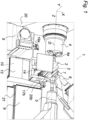
- a machine tool 1 which produces an outer contour 3 on a workpiece 2, 200.
- the Fig. 1 Workpiece 2 shown is a rotor of a screw compressor.
- the workpiece 2 is clamped in a workpiece holder 4a of a workpiece spindle 4 and is supported at the opposite workpiece end by a tailstock 5.
- the workpiece spindle 5 is designed to rotate the workpiece 2 about a rotation axis D in the Z direction of the machine tool 1.
- the machine tool 1 also has a multi-axis movable tool spindle 6 for a tool 7, namely a milling tool, for machining the workpiece 2 in order to produce the screw-symmetrical outer contour 3 of the rotor.
- a Z-slide 8 is provided on the machine bed 9 of the machine tool 1. With this Z-slide 8, which can be moved in the Z direction, the workpiece 2 is supported during its machining with the tool 7 designed as a milling tool.
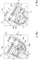
- the Z-slide 8 has a support device 10 with a first support surface 11 designed as a sliding surface and a second support surface 12a, 12b also designed as a sliding surface.
- the first and second support surfaces 11, 12a, 12b are arranged at an angle to one another about the axis of rotation D, which ensures particularly precise support at different angles of attack of the milling tool 7 on the workpiece 2.
- the Z-slide 8 has at least one linearly guided slide 13, 14 with either the first or the second support surface 11, 12a, 12b.
- the first or the second support surface 11, 12a or 12b is adjusted to the workpiece 2 via the respective slide 13, 14. This creates a machine tool 1 with which an outer contour 3 can be quickly produced on a workpiece 2 in a reproducible manner with a high degree of accuracy.
- the first support surface 11 is shown with the first slide 13 in the X direction of the machine tool 1 and the second support surface 12a, 12b with the second slide 14 in the Y direction of the machine tool 1.
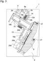
- the second slide 14 is guided linearly on the first slide 13, as in Fig. 2 and 3
- the first and/or second support surface 11, 12a or 12b can also be guided in the radial direction towards the workpiece 2.
- the first carriage 13 has an L-shaped bracket 15.
- the second carriage 14 is movably mounted on the second bracket leg 16b of the bracket 15, specifically along a second linear guide 17b.
- the first bracket leg 16a of the bracket 15 is movably mounted on the Z-slide 8, specifically along a first linear guide 17a. This results in a carriage system on the Z-slide 8.
- the first and second linear guides 17a, 17b each have two profile rails, such as for the second linear guide 17b in Fig. 2 and 3 can be seen, whereby these linear guides 17a, 17b are designed as profile rail guides.
- the two profile rails of the second linear guides 17b are attached to the outside of the second bracket leg 16b of the bracket 15.
- the second carriage 14 surrounds the bracket leg 16b of the first carriage 13 in a frame-like manner.
- the second carriage 14 is moved via a second actuating means 24a, namely a hydraulic cylinder, between the first and second carriages 13, 14.
- a second clamping element 25b is provided between the first and second carriages 13, 14, with which the second carriage 14 can be clamped in its position on the second carriage 13.
- the first slide 13 is moved via a first actuating means 24a, namely hydraulic cylinders, between the first slide 13 and the Z-slide 8.
- a first clamping element 25a is provided between the first carriage 13, 14 and the Z-slide 8, with which the first carriage 13 can be clamped in its position on the Z-slide 8.
- the first support surface 11 is formed by a sliding strip 22.
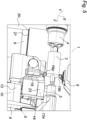
- the second support surfaces 12a, 12b are provided on opposite outer sides 14a, 14b of the second carriage 14, in the XZ plane, as in Fig. 3 This makes it possible to position the second carriage 14 on both opposite longitudinal sides 2a, 2b of the workpiece 2. This is advantageous when two different workpieces 2, 200, namely two rotors of a double screw compressor with different outer contours 3, are manufactured, as can be seen in the comparison between Fig. 2 and Fig. 4 to recognize.
- the Z-slide 8 additionally has a movable tool holder 18 for a first turning tool 19a.
- a second turning tool 19b is located opposite the first turning tool 19a on the workpiece 2.
- the second turning tool 19b is clamped to the tool spindle 6. Both turning tools 19a and 19b machine the rotating workpiece 2 simultaneously to form a pre-machined workpiece 2, the outer contour 3 of which is Fig. 1 which is then further processed.
- the tool holder 18 is arranged at a distance to the left of the support device 10 as seen in the Z direction.
- the machine tool 1 also has a tool changer 20 which is arranged at a left end, as in Fig. 5 shown, is arranged on the Z-bed guide 21 of the machine tool 1.
- the tool changer 20 is designed to automatically change the tool 19a of the Z-slide 8.
Landscapes
- Engineering & Computer Science (AREA)
- Mechanical Engineering (AREA)
- Machine Tool Units (AREA)
Priority Applications (1)
| Application Number | Priority Date | Filing Date | Title |
|---|---|---|---|
| EP23173492.2A EP4464458A1 (fr) | 2023-05-15 | 2023-05-15 | Machine-outil pour la fabrication d'une pièce dotée d'un contour extérieur et procédé correspondant |
Applications Claiming Priority (1)
| Application Number | Priority Date | Filing Date | Title |
|---|---|---|---|
| EP23173492.2A EP4464458A1 (fr) | 2023-05-15 | 2023-05-15 | Machine-outil pour la fabrication d'une pièce dotée d'un contour extérieur et procédé correspondant |
Publications (1)
| Publication Number | Publication Date |
|---|---|
| EP4464458A1 true EP4464458A1 (fr) | 2024-11-20 |
Family
ID=86387051
Family Applications (1)
| Application Number | Title | Priority Date | Filing Date |
|---|---|---|---|
| EP23173492.2A Pending EP4464458A1 (fr) | 2023-05-15 | 2023-05-15 | Machine-outil pour la fabrication d'une pièce dotée d'un contour extérieur et procédé correspondant |
Country Status (1)
| Country | Link |
|---|---|
| EP (1) | EP4464458A1 (fr) |
Citations (4)
| Publication number | Priority date | Publication date | Assignee | Title |
|---|---|---|---|---|
| US20140076115A1 (en) * | 2012-09-17 | 2014-03-20 | Homerun Holdings Corporation | Method and apparatus for cutting one or more grooves in a cylindrical element |
| ES2514866A1 (es) * | 2014-05-23 | 2014-10-28 | Intorex, S.A. | Máquina multifunción para mecanizar piezas de madera |
| EP2149425B1 (fr) | 2008-07-30 | 2016-10-12 | Kapp GmbH | Procédé et dispositif de fabrication d'un rotor de compresseur à vis |
| US20180050432A1 (en) * | 2016-08-17 | 2018-02-22 | Okuma Corporation | Machine tool |
-
2023
- 2023-05-15 EP EP23173492.2A patent/EP4464458A1/fr active Pending
Patent Citations (4)
| Publication number | Priority date | Publication date | Assignee | Title |
|---|---|---|---|---|
| EP2149425B1 (fr) | 2008-07-30 | 2016-10-12 | Kapp GmbH | Procédé et dispositif de fabrication d'un rotor de compresseur à vis |
| US20140076115A1 (en) * | 2012-09-17 | 2014-03-20 | Homerun Holdings Corporation | Method and apparatus for cutting one or more grooves in a cylindrical element |
| ES2514866A1 (es) * | 2014-05-23 | 2014-10-28 | Intorex, S.A. | Máquina multifunción para mecanizar piezas de madera |
| US20180050432A1 (en) * | 2016-08-17 | 2018-02-22 | Okuma Corporation | Machine tool |
Similar Documents
| Publication | Publication Date | Title |
|---|---|---|
| DE69305768T2 (de) | Werkzeugmaschine | |
| DE69714929T2 (de) | Numerisch gesteuerte Werkzeugmaschine zum Drehen und Wälzfräsen von mechanischen Teilen | |
| DE102015001036B4 (de) | Verzahnungs-oder Profilschleifmaschine und Verfahren zum Betreiben einer solchen | |
| CH629407A5 (de) | Werkzeugmaschine. | |
| EP2732895A1 (fr) | Machine-outil pour la fabrication de profilés | |
| EP2762254A1 (fr) | Tour à vilebrequins et fraiseuse ainsi que tourelle revolver à cet effet | |
| DE3030155C2 (fr) | ||
| WO2001098847A2 (fr) | Procede et dispositif pour la mesure et l'usinage de pieces | |
| CH697397B1 (de) | Verfahren und Vorrichtung zum Schleifen eines Profils eines Werkstücks. | |
| CH701326A1 (de) | Schwenkapparat für eine Werkzeugmaschine. | |
| DE8336030U1 (de) | Vorrichtung zum verschwenken einer werkzeugaufnahmevorrichtung, insbesondere eines winkelfraeskopfes, am freien (unteren) ende eines fraesspindelschlittens | |
| EP1017524B1 (fr) | Procede permettant de perforer au moins deux trous en deux temps | |
| EP4464458A1 (fr) | Machine-outil pour la fabrication d'une pièce dotée d'un contour extérieur et procédé correspondant | |
| DE29601808U1 (de) | Vorrichtung zum Bearbeiten von Stangenmaterial, Profilen u.dgl. | |
| EP1832383A2 (fr) | Machine-outil | |
| CH686878A5 (de) | Verfahren und Vorrichtung zur Bearbeitung von Geblaeseschaufeln. | |
| EP4286094A1 (fr) | Procédé et dispositif d'usinage pour l'affûtage de lames d'un outil de coupe rotatif | |
| DE10206949C1 (de) | Zweispindel-Drehmaschine | |
| EP1577040A1 (fr) | Dispositif d'usinage de pièces, notamment pour des pièces pourvues de dents | |
| WO2003024651A1 (fr) | Dispositif de separation par rupture et procede y relatif | |
| DE2615432C3 (de) | Drehmaschine | |
| DE102017105837A1 (de) | Drückmaschine | |
| DE102024112527A1 (de) | Werkstückwechseleinrichtung, Werkzeugmaschine zur Bearbeitung von Werkstücken sowie Werkstückwechselverfahren | |
| DE202021106430U1 (de) | Rundschleifmaschine, insbesondere zum Schälschleifen | |
| DE3626608C1 (en) | Lathe |
Legal Events
| Date | Code | Title | Description |
|---|---|---|---|
| PUAI | Public reference made under article 153(3) epc to a published international application that has entered the european phase |
Free format text: ORIGINAL CODE: 0009012 |
|
| STAA | Information on the status of an ep patent application or granted ep patent |
Free format text: STATUS: THE APPLICATION HAS BEEN PUBLISHED |
|
| AK | Designated contracting states |
Kind code of ref document: A1 Designated state(s): AL AT BE BG CH CY CZ DE DK EE ES FI FR GB GR HR HU IE IS IT LI LT LU LV MC ME MK MT NL NO PL PT RO RS SE SI SK SM TR |
|
| STAA | Information on the status of an ep patent application or granted ep patent |
Free format text: STATUS: REQUEST FOR EXAMINATION WAS MADE |
|
| 17P | Request for examination filed |
Effective date: 20250520 |