EP4464458A1 - Machine tool for producing a workpiece with an outer contour and method therefor - Google Patents
Machine tool for producing a workpiece with an outer contour and method therefor Download PDFInfo
- Publication number
- EP4464458A1 EP4464458A1 EP23173492.2A EP23173492A EP4464458A1 EP 4464458 A1 EP4464458 A1 EP 4464458A1 EP 23173492 A EP23173492 A EP 23173492A EP 4464458 A1 EP4464458 A1 EP 4464458A1
- Authority
- EP
- European Patent Office
- Prior art keywords
- workpiece
- machine tool
- slide
- tool
- support surface
- Prior art date
- Legal status (The legal status is an assumption and is not a legal conclusion. Google has not performed a legal analysis and makes no representation as to the accuracy of the status listed.)
- Pending
Links
Images
Classifications
-
- B—PERFORMING OPERATIONS; TRANSPORTING
- B23—MACHINE TOOLS; METAL-WORKING NOT OTHERWISE PROVIDED FOR
- B23B—TURNING; BORING
- B23B5/00—Turning-machines or devices specially adapted for particular work; Accessories specially adapted therefor
- B23B5/36—Turning-machines or devices specially adapted for particular work; Accessories specially adapted therefor for turning specially-shaped surfaces by making use of relative movement of the tool and work produced by geometrical mechanisms, i.e. forming-lathes
- B23B5/46—Turning-machines or devices specially adapted for particular work; Accessories specially adapted therefor for turning specially-shaped surfaces by making use of relative movement of the tool and work produced by geometrical mechanisms, i.e. forming-lathes for turning helical or spiral surfaces
- B23B5/48—Turning-machines or devices specially adapted for particular work; Accessories specially adapted therefor for turning specially-shaped surfaces by making use of relative movement of the tool and work produced by geometrical mechanisms, i.e. forming-lathes for turning helical or spiral surfaces for cutting grooves, e.g. oil grooves of helicoidal shape
-
- B—PERFORMING OPERATIONS; TRANSPORTING
- B23—MACHINE TOOLS; METAL-WORKING NOT OTHERWISE PROVIDED FOR
- B23B—TURNING; BORING
- B23B25/00—Accessories or auxiliary equipment for turning-machines
-
- B—PERFORMING OPERATIONS; TRANSPORTING
- B23—MACHINE TOOLS; METAL-WORKING NOT OTHERWISE PROVIDED FOR
- B23B—TURNING; BORING
- B23B3/00—General-purpose turning-machines or devices, e.g. centre lathes with feed rod and lead screw; Sets of turning-machines
- B23B3/06—Turning-machines or devices characterised only by the special arrangement of constructional units
- B23B3/065—Arrangements for performing other machining operations, e.g. milling, drilling
-
- B—PERFORMING OPERATIONS; TRANSPORTING
- B23—MACHINE TOOLS; METAL-WORKING NOT OTHERWISE PROVIDED FOR
- B23C—MILLING
- B23C3/00—Milling particular work; Special milling operations; Machines therefor
- B23C3/16—Working surfaces curved in two directions
-
- B—PERFORMING OPERATIONS; TRANSPORTING
- B23—MACHINE TOOLS; METAL-WORKING NOT OTHERWISE PROVIDED FOR
- B23F—MAKING GEARS OR TOOTHED RACKS
- B23F15/00—Methods or machines for making gear wheels of special kinds not covered by groups B23F7/00 - B23F13/00
- B23F15/08—Making intermeshing rotors, e.g. of pumps
-
- B—PERFORMING OPERATIONS; TRANSPORTING
- B23—MACHINE TOOLS; METAL-WORKING NOT OTHERWISE PROVIDED FOR
- B23Q—DETAILS, COMPONENTS, OR ACCESSORIES FOR MACHINE TOOLS, e.g. ARRANGEMENTS FOR COPYING OR CONTROLLING; MACHINE TOOLS IN GENERAL CHARACTERISED BY THE CONSTRUCTION OF PARTICULAR DETAILS OR COMPONENTS; COMBINATIONS OR ASSOCIATIONS OF METAL-WORKING MACHINES, NOT DIRECTED TO A PARTICULAR RESULT
- B23Q1/00—Members which are comprised in the general build-up of a form of machine, particularly relatively large fixed members
- B23Q1/72—Auxiliary arrangements; Interconnections between auxiliary tables and movable machine elements
- B23Q1/76—Steadies; Rests
- B23Q1/766—Steadies or rests moving together with the tool support
Definitions
- the invention relates to a machine tool for producing a workpiece with an outer contour, in particular a rotor of a screw compressor, and a method therefor.
- the invention therefore has the object of improving a method of the type described above in terms of cycle time, without thereby reducing the reproducibility in terms of manufacturing accuracy.
- the invention solves the problem by the features of claim 1.
- first and a second support surface in particular a sliding surface, of a support device, whereby at least these two support surfaces are arranged at an angle offset from one another around the axis of rotation, deflections can initially be prevented even in the case of comparatively heavy workpieces, for example due to the workpiece weight or Machining forces, an exact positioning is ensured and thus an external contour is produced in a reproducible manner.
- the first and/or the second support surface is adjusted to the workpiece via at least one, in particular linear, guided slide that is provided on a Z-slide of the machine tool.
- the respective support surface can be moved and adjusted comparatively quickly and with precise positioning via the slide system.
- the method according to the invention therefore enables short cycle times with high manufacturing accuracy, which significantly improves the reproducibility of the method.
- the second support surface is positioned via a second slide, which is guided on the first slide. This positioning of the second support surface can take place, for example, in the Y direction of the machine tool.
- the longitudinal directions of the first and/or second support surface run essentially in the Z direction of the machine tool in order to further increase the accuracy of the process. This can be particularly advantageous for workpieces with a cylindrical outer envelope contour.
- the first and/or second support surface is guided towards the workpiece in a radial direction. This further simplifies the handling of the process. In addition, a radial adjustment can lead to stable support of the workpiece in a relatively reproducible manner.
- the supported workpiece is machined while rotating about the axis of rotation, which in particular runs centrally through the workpiece, in order to be able to further reduce the cycle time.
- the method according to the invention can be distinguished for the rapid production of workpieces with mutually different outer contours.
- the support device has two second support surfaces, each of which supports one of the workpieces, wherein the second support surfaces are arranged on opposite outer sides of the second carriage. This is particularly advantageous in the case of two rotors of a double-screw compressor with different outer contours.
- the support according to the invention can also be part of a complete machining process in which, before the workpiece is supported, a pre-machining of the workpiece takes place, in which the outer contour is introduced with allowance using two turning tools that are located opposite one another on the workpiece, in particular diametrically opposite one another. This can further reduce the cycle time in the production of workpieces with precise dimensions.
- the invention also aims to modify the design of a machine tool in such a way that an external contour can be quickly created on a workpiece in a reproducible manner with a high degree of accuracy.
- the machine tool should be characterized by structural simplicity and robustness.
- the invention solves the problem by claim 8.
- the workpiece can be machined more precisely and stably.
- the support device has a first and a second support surface, in particular a sliding surface, which are arranged at an angle offset from one another around the axis of rotation.
- the Z-slide also has at least one, in particular linearly guided, slide on which the first and/or second support surface is provided, this support device can be positioned precisely on the workpiece in a reduced time.
- the machine tool according to the invention can therefore also ensure a short cycle time when producing workpieces.
- a first carriage guided on the Z-slide, in particular in the X-direction of the machine tool, has the first support surface.
- a second carriage guided on the first carriage in particular in the Y direction of the machine tool, has the second support surface.
- This carriage system can also simplify the handling of the support.
- the first carriage has a, in particular angled, console, on the second console leg of which the second carriage is movably mounted in order to further simplify the design of the machine tool.
- the console can have two legs that are angled at a right angle to each other.
- a first linear guide in particular a profile rail guide, is provided between the Z-slide and the first slide.
- a second linear guide in particular a profile rail guide, is provided between the first and second carriage.
- the design of the machine tool can be further simplified, for example, if the first support surface is formed by a sliding strip and/or the second support surface is formed by at least one sliding plate.
- the second carriage has two second support surfaces which are provided on opposite outer sides of the second carriage in order to be able to adjust the outer envelope contour from different sides in accordance with the requirements of the machining.
- the outer sides each lie in an X-Z plane of the machine tool.
- the Z-slide additionally has a movable tool holder for a tool, in particular a turning tool, which tool holder is arranged.
- the tool holder is arranged next to the support device when viewed in the Z direction.
- the machine tool has a tool changer which is arranged at one end of the Z-bed guide of the machine tool and is designed to change the tool of the tool holder of the Z-slide.
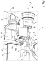
- a machine tool 1 which produces an outer contour 3 on a workpiece 2, 200.
- the Fig. 1 Workpiece 2 shown is a rotor of a screw compressor.
- the workpiece 2 is clamped in a workpiece holder 4a of a workpiece spindle 4 and is supported at the opposite workpiece end by a tailstock 5.
- the workpiece spindle 5 is designed to rotate the workpiece 2 about a rotation axis D in the Z direction of the machine tool 1.
- the machine tool 1 also has a multi-axis movable tool spindle 6 for a tool 7, namely a milling tool, for machining the workpiece 2 in order to produce the screw-symmetrical outer contour 3 of the rotor.
- a Z-slide 8 is provided on the machine bed 9 of the machine tool 1. With this Z-slide 8, which can be moved in the Z direction, the workpiece 2 is supported during its machining with the tool 7 designed as a milling tool.
- the Z-slide 8 has a support device 10 with a first support surface 11 designed as a sliding surface and a second support surface 12a, 12b also designed as a sliding surface.
- the first and second support surfaces 11, 12a, 12b are arranged at an angle to one another about the axis of rotation D, which ensures particularly precise support at different angles of attack of the milling tool 7 on the workpiece 2.
- the Z-slide 8 has at least one linearly guided slide 13, 14 with either the first or the second support surface 11, 12a, 12b.
- the first or the second support surface 11, 12a or 12b is adjusted to the workpiece 2 via the respective slide 13, 14. This creates a machine tool 1 with which an outer contour 3 can be quickly produced on a workpiece 2 in a reproducible manner with a high degree of accuracy.
- the first support surface 11 is shown with the first slide 13 in the X direction of the machine tool 1 and the second support surface 12a, 12b with the second slide 14 in the Y direction of the machine tool 1.
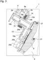
- the second slide 14 is guided linearly on the first slide 13, as in Fig. 2 and 3
- the first and/or second support surface 11, 12a or 12b can also be guided in the radial direction towards the workpiece 2.
- the first carriage 13 has an L-shaped bracket 15.
- the second carriage 14 is movably mounted on the second bracket leg 16b of the bracket 15, specifically along a second linear guide 17b.
- the first bracket leg 16a of the bracket 15 is movably mounted on the Z-slide 8, specifically along a first linear guide 17a. This results in a carriage system on the Z-slide 8.
- the first and second linear guides 17a, 17b each have two profile rails, such as for the second linear guide 17b in Fig. 2 and 3 can be seen, whereby these linear guides 17a, 17b are designed as profile rail guides.
- the two profile rails of the second linear guides 17b are attached to the outside of the second bracket leg 16b of the bracket 15.
- the second carriage 14 surrounds the bracket leg 16b of the first carriage 13 in a frame-like manner.
- the second carriage 14 is moved via a second actuating means 24a, namely a hydraulic cylinder, between the first and second carriages 13, 14.
- a second clamping element 25b is provided between the first and second carriages 13, 14, with which the second carriage 14 can be clamped in its position on the second carriage 13.
- the first slide 13 is moved via a first actuating means 24a, namely hydraulic cylinders, between the first slide 13 and the Z-slide 8.
- a first clamping element 25a is provided between the first carriage 13, 14 and the Z-slide 8, with which the first carriage 13 can be clamped in its position on the Z-slide 8.
- the first support surface 11 is formed by a sliding strip 22.
- the second support surfaces 12a, 12b are provided on opposite outer sides 14a, 14b of the second carriage 14, in the XZ plane, as in Fig. 3 This makes it possible to position the second carriage 14 on both opposite longitudinal sides 2a, 2b of the workpiece 2. This is advantageous when two different workpieces 2, 200, namely two rotors of a double screw compressor with different outer contours 3, are manufactured, as can be seen in the comparison between Fig. 2 and Fig. 4 to recognize.
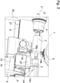
- the Z-slide 8 additionally has a movable tool holder 18 for a first turning tool 19a.
- a second turning tool 19b is located opposite the first turning tool 19a on the workpiece 2.
- the second turning tool 19b is clamped to the tool spindle 6. Both turning tools 19a and 19b machine the rotating workpiece 2 simultaneously to form a pre-machined workpiece 2, the outer contour 3 of which is Fig. 1 which is then further processed.
- the tool holder 18 is arranged at a distance to the left of the support device 10 as seen in the Z direction.
- the machine tool 1 also has a tool changer 20 which is arranged at a left end, as in Fig. 5 shown, is arranged on the Z-bed guide 21 of the machine tool 1.
- the tool changer 20 is designed to automatically change the tool 19a of the Z-slide 8.
Landscapes
- Engineering & Computer Science (AREA)
- Mechanical Engineering (AREA)
- Machine Tool Units (AREA)
Abstract
Es wird eine Werkzeugmaschine (1) zur Herstellung eines Werkstücks (2) mit einer Außenkontur (3), insbesondere eines Rotors eines Schraubenverdichters, und ein Verfahren hierzu gezeigt. Um bei geringen Taktzeiten eine hohe Herstellungsgenauigkeit zu gewährleisten, wird vorgeschlagen, dass das Werkstück (2, 200) an der Au-ßenkontur (3) zumindest an einer ersten und einer zweiten Abstützfläche (11, 12a, 12b), insbesondere Gleitfläche, einer Abstützeinrichtung (10) abgestützt wird, wobei zumindest diese beiden Abstützflächen (11, 12a, 12b) um die Drehachse (D) zueinander winkelversetzt angeordnet sind, wobei die erste und/oder die zweite Abstützfläche (11, 12a, 12b) über zumindest einen, insbesondere linear, geführten Schlitten (13, 14) am Werkstück (2, 200) angestellt wird, der an einem Z-Schlitten (8) der Werkzeugmaschine (1) vorgesehen ist.

Description
Die Erfindung betrifft eine Werkzeugmaschine zur Herstellung eines Werkstücks mit einer Außenkontur, insbesondere eines Rotors eines Schraubenverdichters, und ein Verfahren hierzu.The invention relates to a machine tool for producing a workpiece with an outer contour, in particular a rotor of a screw compressor, and a method therefor.
Um an einem Rotor eines Schraubenverdichters eine Außenkontur zu erzeugen, sind verschiedenste spanende Verfahren und Werkzeugmaschinen hierfür bekannt (vgl.
Die Erfindung hat sich daher die Aufgabe gestellt, ein Verfahren der eingangs geschilderten Art in der Taktzeit zu verbessern, ohne damit aber die Reproduzierbarkeit in der Herstellungsgenauigkeit zu verringern.The invention therefore has the object of improving a method of the type described above in terms of cycle time, without thereby reducing the reproducibility in terms of manufacturing accuracy.
Die Erfindung löst die gestellte Aufgabe durch die Merkmale des Anspruchs 1.The invention solves the problem by the features of
Indem das Werkstück an der Außenkontur zumindest an einer ersten und einer zweiten Abstützfläche, insbesondere Gleitfläche, einer Abstützeinrichtung abgestützt wird, wobei zumindest diese beiden Abstützflächen um die Drehachse zueinander winkelversetzt angeordnet sind, kann zunächst auch bei vergleichsweise schweren Werkstücken Durchbiegungen, beispielsweise aufgrund des Werkstückgewichts oder von Bearbeitungskräften, eine exakte Positionierung sichergestellt und damit reproduzierbar eine Außenkontur erzeugt werden. Um durch dieses Anstellen der Abstützflächen die Taktzeit dennoch kleinzuhalten, wird vorgeschlagen, dass die erste und/oder die zweite Abstützfläche über zumindest einen, insbesondere linear, geführten Schlitten am Werkstück angestellt wird, der an einem Z-Schlitten der Werkzeugmaschine vorgesehen ist. Über das Schlittensystem kann nämlich die jeweilige Abstützfläche vergleichsweise schnell und positionsgenau verfahren und damit angestellt werden. Das erfindungsgemäße Verfahren ermöglicht daher kurze Taktzeiten bei hoher Herstellungsgenauigkeit, was die Reproduzierbarkeit des Verfahrens erheblich verbessert.By supporting the workpiece on the outer contour at least on a first and a second support surface, in particular a sliding surface, of a support device, whereby at least these two support surfaces are arranged at an angle offset from one another around the axis of rotation, deflections can initially be prevented even in the case of comparatively heavy workpieces, for example due to the workpiece weight or Machining forces, an exact positioning is ensured and thus an external contour is produced in a reproducible manner. In order to keep the cycle time short by adjusting the support surfaces in this way, it is proposed that the first and/or the second support surface is adjusted to the workpiece via at least one, in particular linear, guided slide that is provided on a Z-slide of the machine tool. The respective support surface can be moved and adjusted comparatively quickly and with precise positioning via the slide system. The method according to the invention therefore enables short cycle times with high manufacturing accuracy, which significantly improves the reproducibility of the method.
Vorzugsweise wird die erste Abstützfläche mit dem ersten am Z-Schlitten geführten Schlitten angestellt. Diese Anstellung der ersten Abstützfläche kann beispielsweise in X-Richtung der Werkzeugmaschine erfolgen.Preferably, the first support surface is positioned with the first slide guided on the Z-slide. This positioning of the first support surface can be carried out, for example, in the X-direction of the machine tool.
Vorstellbar ist weiter, dass die zweite Abstützfläche über einen zweiten Schlitten angestellt wird, welcher zweite Schlitten am ersten Schlitten geführt ist. Diese Anstellung der zweiten Abstützfläche kann beispielsweise in Y-Richtung der Werkzeugmaschine erfolgen.It is also conceivable that the second support surface is positioned via a second slide, which is guided on the first slide. This positioning of the second support surface can take place, for example, in the Y direction of the machine tool.
Damit kann bei minimalem Zeitaufwand eine exakte und positionsgenaue Abstützung des Werkstücks zur Verfügung gestellt werden, wodurch das spanende Bearbeiten besonders exakt und stabil ausgeführt werden kann.This means that precise and precisely positioned support of the workpiece can be provided with minimal expenditure of time, allowing machining to be carried out particularly precisely and stably.
Beispielsweise verlaufen die Längsrichtungen der ersten und/oder zweiten Abstützfläche im Wesentlichen in Z-Richtung der Werkzeugmaschine, um die Genauigkeit des Verfahrens weiter zu erhöhen. Insbesondere bei Werkstücken mit einer zylindrischen äußeren Hüllkontur kann vorteilhaft sein.For example, the longitudinal directions of the first and/or second support surface run essentially in the Z direction of the machine tool in order to further increase the accuracy of the process. This can be particularly advantageous for workpieces with a cylindrical outer envelope contour.
Beispielsweise wird die erste und/oder zweite Abstützfläche in radiale Richtung an das Werkstück hingeführt. Dies vereinfacht die Handhabung des Verfahrens weiter. Zudem kann eine radiale Anstellung vergleichsweise reproduzierbar zu einer standfesten Abstützung des Werkstücks führen.For example, the first and/or second support surface is guided towards the workpiece in a radial direction. This further simplifies the handling of the process. In addition, a radial adjustment can lead to stable support of the workpiece in a relatively reproducible manner.
Vorstellbar ist, dass der Schlitten nach dem Hinführen der ersten und/oder zweiten Abstützfläche in seiner Position festgeklemmt wird. Dies stellt auch bei hohen Kräften auf die Abstützung eine genaue Bearbeitung sicher.It is conceivable that the carriage is clamped in position after the first and/or second support surface has been brought in. This ensures precise machining even when high forces are applied to the support.
Vorzugsweise wird das abgestützte Werkstück unter Drehung um die, insbesondere durch das Werkstück zentrisch verlaufende, Drehachse spanend bearbeitet wird, um die Taktzeit weiter verringern zu können.Preferably, the supported workpiece is machined while rotating about the axis of rotation, which in particular runs centrally through the workpiece, in order to be able to further reduce the cycle time.
Insbesondere kann sich aber das erfindungsgemäße Verfahren zur taktschnellen Herstellung von Werkstücken mit zueinander unterschiedlichen Außenkonturen auszeichnen. Beispielsweise indem nacheinander zwei Werkstücke, hergestellt werden, wobei die Abstützeinrichtung zwei zweite Abstützflächen aufweist, die jeweils eines der Werkstücke abstützen, wobei die zweiten Abstützflächen an einander gegenüberliegenden Außenseiten des zweiten Schlittens angeordnet sind. Dies ist insbesondere bei zwei in der Außenkontur verschiedene Rotoren eines Doppel-Schraubenverdichters von Vorteil.In particular, however, the method according to the invention can be distinguished for the rapid production of workpieces with mutually different outer contours. For example, by producing two workpieces one after the other, wherein the support device has two second support surfaces, each of which supports one of the workpieces, wherein the second support surfaces are arranged on opposite outer sides of the second carriage. This is particularly advantageous in the case of two rotors of a double-screw compressor with different outer contours.
Beispielsweise kann die erfindungsgemäße Abstützung auch Teil eines Komplettbearbeitungsverfahrens sein, in dem vor der Abstützung des Werkstücks eine spanende Vorbearbeitung des Werkstücks stattfindet, bei der mit zwei einander am Werkstück, insbesondere diametral, gegenüberliegenden Drehwerkzeugen die Außenkontur mit Aufmaß eingebracht wird. Dies kann die Taktzeit in der Herstellung formgenauer Werkstücke weiter verringern.For example, the support according to the invention can also be part of a complete machining process in which, before the workpiece is supported, a pre-machining of the workpiece takes place, in which the outer contour is introduced with allowance using two turning tools that are located opposite one another on the workpiece, in particular diametrically opposite one another. This can further reduce the cycle time in the production of workpieces with precise dimensions.
Die Erfindung hat sich außerdem die Aufgabe gestellt, eine Werkzeugmaschine zu derart konstruktiv zu verändern, dass damit reproduzierbar mit einer hohen Genauigkeit schnell an einem Werkstück eine Außenkontur erzeugt werden kann. Zudem soll sich die Werkzeugmaschine durch eine konstruktive Einfachheit und Robustheit auszeichnen.The invention also aims to modify the design of a machine tool in such a way that an external contour can be quickly created on a workpiece in a reproducible manner with a high degree of accuracy. In addition, the machine tool should be characterized by structural simplicity and robustness.
Die Erfindung löst die gestellte Aufgabe durch den Anspruch 8.The invention solves the problem by
Indem an einem mit einem Z-Schlitten an einem Maschinenbett der Werkzeugmaschine, der eine Abstützeinrichtung zum Abstützen des eingespannten Werkstücks bei dessen spanenden Bearbeitung aufweist, kann die Werkstückbearbeitung genauer und stabiler erfolgen. Dies insbesondere dann, wenn die Abstützeinrichtung eine erste und eine zweite Abstützfläche, insbesondere Gleitfläche, aufweist, die zueinander um die Drehachse winkelversetzt angeordnet sind. Weist zudem der Z-Schlitten zusätzlich zumindest einen, insbesondere linear, geführten Schlitten aufweist, an dem die erste und/oder zweite Abstützfläche vorgesehen ist, kann diese Abstützeinrichtung zeitreduziert an das Werkstück exakt angestellt werden. Die erfindungsgemäße Werkzeugmaschine kann daher auch bei der Herstellung von Werkstücken eine geringe Taktzeit sicherstellen.By using a Z-slide on a machine bed of the machine tool, which has a support device for supporting the clamped workpiece during machining, the workpiece can be machined more precisely and stably. This is particularly the case when the support device has a first and a second support surface, in particular a sliding surface, which are arranged at an angle offset from one another around the axis of rotation. If the Z-slide also has at least one, in particular linearly guided, slide on which the first and/or second support surface is provided, this support device can be positioned precisely on the workpiece in a reduced time. The machine tool according to the invention can therefore also ensure a short cycle time when producing workpieces.
Vorzugsweise weist ein am Z-Schlitten, insbesondere in X-Richtung der Werkzeugmaschine, geführter erster Schlitten die erste Abstützfläche auf.Preferably, a first carriage guided on the Z-slide, in particular in the X-direction of the machine tool, has the first support surface.
Vorstellbar ist weiter, dass ein am ersten Schlitten, insbesondere in Y-Richtung der Werkzeugmaschine, geführter zweiter Schlitten die zweite Abstützfläche aufweist. Mit diesem Schlittensystem kann zudem die Handhabung der Abstützung vereinfacht werden.It is also conceivable that a second carriage guided on the first carriage, in particular in the Y direction of the machine tool, has the second support surface. This carriage system can also simplify the handling of the support.
Vorstellbar ist, dass der erste Schlitten eine, insbesondere abgewinkelte, Konsole aufweist, an deren zweiten Konsolenschenkel der zweite Schlitten beweglich gelagert ist, um damit die Konstruktion der Werkzeugmaschine weiter zu vereinfachen. Die Konsole kann zwei Schenkeln aufweisen, die in einem rechten Winkel zueinander abgewinkelt sind.It is conceivable that the first carriage has a, in particular angled, console, on the second console leg of which the second carriage is movably mounted in order to further simplify the design of the machine tool. The console can have two legs that are angled at a right angle to each other.
Vorzugsweise ist zwischen Z-Schlitten und ersten Schlitten eine erste Linearführung, insbesondere Profilschienenführung, vorgesehen.Preferably, a first linear guide, in particular a profile rail guide, is provided between the Z-slide and the first slide.
Beispielsweise ist zwischen erstem und zweitem Schlitten eine zweite Linearführung, insbesondere Profilschienenführung, vorgesehen ist.For example, a second linear guide, in particular a profile rail guide, is provided between the first and second carriage.
Die Konstruktion der Werkzeugmaschine kann beispielsweise weiter vereinfacht werden, wenn die erste Abstützfläche von einer Gleitleiste und/oder die zweite Abstützfläche von zumindest einer Gleitplatte ausgebildet wird.The design of the machine tool can be further simplified, for example, if the first support surface is formed by a sliding strip and/or the second support surface is formed by at least one sliding plate.
Vorzugsweise weist der zweite Schlitten zwei zweite Abstützflächen auf, die an einander gegenüberliegenden Außenseiten des zweiten Schlittens vorgesehen sind, um damit entsprechend den Anforderungen der spanenden Bearbeitung an der äußeren Hüllkontur von unterschiedlichen Seiten anstellen zu können. Vorzugsweise liegen die Außenseiten je in einer X-Z-Ebene der Werkzeugmaschine.Preferably, the second carriage has two second support surfaces which are provided on opposite outer sides of the second carriage in order to be able to adjust the outer envelope contour from different sides in accordance with the requirements of the machining. Preferably, the outer sides each lie in an X-Z plane of the machine tool.
Weitere Bearbeitungsschritte können von der Werkzeugmaschine, beispielsweise zur Vorbearbeitung, ausgeführt werden, wenn dass der Z-Schlitten zusätzlich einen beweglichen Werkzeughalter für ein Werkzeug, insbesondere Drehwerkzeug, aufweist, welcher Werkzeughalter angeordnet ist. Beispielsweise ist der Werkzeughalter in Z-Richtung gesehen neben der Abstützeinrichtung angeordnet.Further machining steps can be carried out by the machine tool, for example for pre-machining, if the Z-slide additionally has a movable tool holder for a tool, in particular a turning tool, which tool holder is arranged. For example, the tool holder is arranged next to the support device when viewed in the Z direction.
Dies beispielsweise auch mit kurzen Taktzeiten, wenn die Werkzeugmaschine einen Werkzeugwechsler aufweist, der an einem Ende der Z-Bettführung der Werkzeugmaschine angeordnet und ausgebildet ist, um das Werkzeug des Werkzeughalters des Z-Schlittens zu wechseln.This is also possible, for example, with short cycle times if the machine tool has a tool changer which is arranged at one end of the Z-bed guide of the machine tool and is designed to change the tool of the tool holder of the Z-slide.
In den Figuren ist beispielsweise der Erfindungsgegenstand anhand eines Ausführungsbeispiels näher dargestellt. Es zeigen
- Fig. 1
- eine dreidimensionale Teilansicht zu einer Werkzeugmaschine beim spanenden Bearbeiten eines vorbearbeiteten Werkstücks,
- Fig. 2
- eine Stirnansicht auf das Werkstück der
Fig. 1 mit einer angestellter Abstützeinrichtung, - Fig. 3
- eine Schnittansicht durch die nach
Fig. 2 dargestellte Abstützeinrichtung, - Fig. 4
- eine Stirnansicht auf ein anderes Werkstück mit einer angestellter Abstützeinrichtung und
- Fig. 5
- eine dreidimensionale Teilansicht zu der Werkzeugmaschine beim spanenden Vorbearbeiten des Werkstücks nach
Fig. 1 .
- Fig. 1
- a three-dimensional partial view of a machine tool during machining of a pre-machined workpiece,
- Fig. 2
- a front view of the workpiece of the
Fig. 1 with an attached support device, - Fig. 3
- a sectional view through the
Fig. 2 illustrated support device, - Fig. 4
- a front view of another workpiece with an adjusted support device and
- Fig. 5
- a three-dimensional partial view of the machine tool during machining of the workpiece after
Fig. 1 .
Nach
Das Werkstück 2 ist in einem Werkstückhalter 4a einer Werkstückspindel 4 eingespannt und wird am gegenüberliegenden Werkstückende von einem Reitstock 5 abgestützt. Die Werkstückspindel 5 ist ausgebildet, das Werkstück 2 um eine Drehachse D in Z-Richtung der Werkzeugmaschine 1 zu drehen.The
Die Werkzeugmaschine 1 weist zudem eine mehrachsig bewegbare Werkzeugspindel 6 für ein Werkzeug 7, nämlich Fräswerkzeug, zur spanenden Bearbeitung des Werkstücks 2 auf, um damit die schraubensymmetrische Außenkontur 3 des Rotors zu erzeugen.The
Damit dies reproduzierbar mit hoher Genauigkeit und geringer Taktzeit erfolgen kann, ist erfindungsgemäß ein Z-Schlitten 8 am Maschinenbett 9 der Werkzeugmaschine 1 vorgesehen. Mit diesem in Z-Richtung bewegbaren Z-Schlitten 8 wird das Werkstück 2 bei seiner Bearbeitung mit dem als Fräswerkzeug ausgeführten Werkzeug 7 abgestützt. Hierzu weist -wie in
Diese Anstellung ist auch verfahrensschnell möglich, da der Z-Schlitten 8 zumindest einen linear geführten Schlitten 13, 14 mit entweder der ersten oder der zweiten Abstützfläche 11, 12a, 12b aufweist. Über den betreffenden Schlitten 13, 14 wird die erste oder die zweite Abstützfläche 11, 12a oder 12b an das Werkstück 2 angestellt. Damit ist eine Werkzeugmaschine 1 geschaffen, mit der reproduzierbar mit einer hohen Genauigkeit schnell an einem Werkstück 2 eine Außenkontur 3 erzeugt werden kann.This adjustment is also possible in a fast process, since the Z-
Wie in
Wie der
Die erste und zweite Linearführungen 17a, 17b weisen je zwei Profilschienen auf, wie beispielsweise für die zweite Linearführung 17b in
Zudem umgreift der zweite Schlitten 14 den Konsolenschenkel 16b des ersten Schlittens 13 rahmenartig. Über ein zweites Stellmittel 24a, nämlich Hydraulikzylinder, zwischen dem ersten und zweiten Schlitten 13, 14 wird der zweite Schlitten 14 bewegt. Zudem ist ein zweites Klemmelement 25b zwischen erstem und zweitem Schlitten 13, 14 vorgesehen, womit der zweite Schlitten 14 in seiner Position am zweiten Schlitten 13 festgeklemmt werden kann.In addition, the
Über ein erstes Stellmittel 24a, nämlich Hydraulikzylinder, zwischen dem ersten Schlitten 13 und dem Z-Schlitten 8 wird der erste Schlitten 13 bewegt. Zudem ist ein erstes Klemmelement 25a zwischen erstem Schlitten 13, 14 und Z-Schlitten 8 vorgesehen, womit der erste Schlitten 13 in seiner Position am Z-Schlitten 8 festgeklemmt werden kann.The
Wie zu dem in der
Beispielsweise ist aufgrund eines begrenzten Schwenkbereiches des Werkzeugs 7 an der, insbesondere oberen, Werkzeugspindel 6, für die Herstellung unterschiedlicher Schraubensteigungsrichtungen die wahlweise Anstellung des Werkzeugs 7, insbesondere in Y-Richtung, oberhalb oder unterhalb des Werkstückes 2 erforderlich. Dies kann mit dem zweiten Schlitten 14 und der Option der wahlweise anstellbaren Abstützflächen 12a, 12b elegant gelöst werden.For example, due to a limited swivel range of the
Nach
Damit sich der Werkzeughalter 18 und die Abstützeinrichtung 10 nicht gegenseitig behindern, ist der Werkzeughalter 18 in Z-Richtung gesehen links neben der Abstützeinrichtung 10 auf Abstand angeordnet.In order to ensure that the
Die Werkzeugmaschine 1 weist zudem einen Werkzeugwechsler 20 auf, der an einem linken Ende, wie in
Claims (15)
Priority Applications (1)
| Application Number | Priority Date | Filing Date | Title |
|---|---|---|---|
| EP23173492.2A EP4464458A1 (en) | 2023-05-15 | 2023-05-15 | Machine tool for producing a workpiece with an outer contour and method therefor |
Applications Claiming Priority (1)
| Application Number | Priority Date | Filing Date | Title |
|---|---|---|---|
| EP23173492.2A EP4464458A1 (en) | 2023-05-15 | 2023-05-15 | Machine tool for producing a workpiece with an outer contour and method therefor |
Publications (1)
| Publication Number | Publication Date |
|---|---|
| EP4464458A1 true EP4464458A1 (en) | 2024-11-20 |
Family
ID=86387051
Family Applications (1)
| Application Number | Title | Priority Date | Filing Date |
|---|---|---|---|
| EP23173492.2A Pending EP4464458A1 (en) | 2023-05-15 | 2023-05-15 | Machine tool for producing a workpiece with an outer contour and method therefor |
Country Status (1)
| Country | Link |
|---|---|
| EP (1) | EP4464458A1 (en) |
Citations (4)
| Publication number | Priority date | Publication date | Assignee | Title |
|---|---|---|---|---|
| US20140076115A1 (en) * | 2012-09-17 | 2014-03-20 | Homerun Holdings Corporation | Method and apparatus for cutting one or more grooves in a cylindrical element |
| ES2514866A1 (en) * | 2014-05-23 | 2014-10-28 | Intorex, S.A. | Multifunction machine for machining wooden parts (Machine-translation by Google Translate, not legally binding) |
| EP2149425B1 (en) | 2008-07-30 | 2016-10-12 | Kapp GmbH | Method and apparatus for producing a screw compressor rotor |
| US20180050432A1 (en) * | 2016-08-17 | 2018-02-22 | Okuma Corporation | Machine tool |
-
2023
- 2023-05-15 EP EP23173492.2A patent/EP4464458A1/en active Pending
Patent Citations (4)
| Publication number | Priority date | Publication date | Assignee | Title |
|---|---|---|---|---|
| EP2149425B1 (en) | 2008-07-30 | 2016-10-12 | Kapp GmbH | Method and apparatus for producing a screw compressor rotor |
| US20140076115A1 (en) * | 2012-09-17 | 2014-03-20 | Homerun Holdings Corporation | Method and apparatus for cutting one or more grooves in a cylindrical element |
| ES2514866A1 (en) * | 2014-05-23 | 2014-10-28 | Intorex, S.A. | Multifunction machine for machining wooden parts (Machine-translation by Google Translate, not legally binding) |
| US20180050432A1 (en) * | 2016-08-17 | 2018-02-22 | Okuma Corporation | Machine tool |
Similar Documents
| Publication | Publication Date | Title |
|---|---|---|
| DE69305768T2 (en) | Machine tool | |
| DE69714929T2 (en) | Numerically controlled machine tool for turning and hobbing mechanical parts | |
| DE102015001036B4 (en) | Gear or profile grinding machine and method for operating such | |
| CH629407A5 (en) | MACHINE TOOL. | |
| EP2732895A1 (en) | Machine tool for manufacturing profiles | |
| EP2762254A1 (en) | Crankshaft turning and milling machine and tool turret for same | |
| DE3030155C2 (en) | ||
| WO2001098847A2 (en) | Method and device for measuring and machining workpieces | |
| CH697397B1 (en) | Method and apparatus for grinding a profile of a workpiece. | |
| CH701326A1 (en) | Swivelable apparatus for e.g. four-axis machine tool, for processing work-piece, has bearing units designed such that rotation center is excentric to centre of bearing pin and/or bearing borehole | |
| DE8336030U1 (en) | DEVICE FOR SWIVELING A TOOL-RECEIVING DEVICE, IN PARTICULAR AN ANGLE MILLING HEAD, AT THE FREE (LOWER) END OF A MILLING SPINDLE SLIDE | |
| EP1017524B1 (en) | Method for drilling at least two holes in a two-step cycle | |
| EP4464458A1 (en) | Machine tool for producing a workpiece with an outer contour and method therefor | |
| DE29601808U1 (en) | Device for processing bar material, profiles and the like. | |
| EP1832383A2 (en) | Machine tool | |
| CH686878A5 (en) | Method and appts. for machining blower blades | |
| EP4286094A1 (en) | Method and machining device for sharpening the cutting edges of a rotary cutting tool | |
| DE10206949C1 (en) | Double-spindle lathe has spindles on parallel axes with their workpiece holders against each other, and independent right angled movements by the tailstock and steadyrest | |
| EP1577040A1 (en) | Device for machining workpieces, in particular for workpieces provided with teeth | |
| WO2003024651A1 (en) | Fracture-splitting device and fracture-splitting method | |
| DE2615432C3 (en) | Lathe | |
| DE102017105837A1 (en) | spinning machine | |
| DE102024112527A1 (en) | Workpiece changing device, machine tool for machining workpieces and workpiece changing procedure | |
| DE202021106430U1 (en) | Cylindrical grinding machine, in particular for peel grinding | |
| DE3626608C1 (en) | Lathe |
Legal Events
| Date | Code | Title | Description |
|---|---|---|---|
| PUAI | Public reference made under article 153(3) epc to a published international application that has entered the european phase |
Free format text: ORIGINAL CODE: 0009012 |
|
| STAA | Information on the status of an ep patent application or granted ep patent |
Free format text: STATUS: THE APPLICATION HAS BEEN PUBLISHED |
|
| AK | Designated contracting states |
Kind code of ref document: A1 Designated state(s): AL AT BE BG CH CY CZ DE DK EE ES FI FR GB GR HR HU IE IS IT LI LT LU LV MC ME MK MT NL NO PL PT RO RS SE SI SK SM TR |
|
| STAA | Information on the status of an ep patent application or granted ep patent |
Free format text: STATUS: REQUEST FOR EXAMINATION WAS MADE |
|
| 17P | Request for examination filed |
Effective date: 20250520 |