EP4464221A1 - Reinigungsbürste und intelligente reinigungsvorrichtung - Google Patents
Reinigungsbürste und intelligente reinigungsvorrichtung Download PDFInfo
- Publication number
- EP4464221A1 EP4464221A1 EP22918176.3A EP22918176A EP4464221A1 EP 4464221 A1 EP4464221 A1 EP 4464221A1 EP 22918176 A EP22918176 A EP 22918176A EP 4464221 A1 EP4464221 A1 EP 4464221A1
- Authority
- EP
- European Patent Office
- Prior art keywords
- limiting
- cleaning brush
- guide sleeve
- shaft rod
- brush according
- Prior art date
- Legal status (The legal status is an assumption and is not a legal conclusion. Google has not performed a legal analysis and makes no representation as to the accuracy of the status listed.)
- Pending
Links
Images


Classifications
-
- A—HUMAN NECESSITIES
- A47—FURNITURE; DOMESTIC ARTICLES OR APPLIANCES; COFFEE MILLS; SPICE MILLS; SUCTION CLEANERS IN GENERAL
- A47L—DOMESTIC WASHING OR CLEANING; SUCTION CLEANERS IN GENERAL
- A47L11/00—Machines for cleaning floors, carpets, furniture, walls, or wall coverings
-
- A—HUMAN NECESSITIES
- A46—BRUSHWARE
- A46B—BRUSHES
- A46B13/00—Brushes with driven brush bodies or carriers
- A46B13/001—Cylindrical or annular brush bodies
-
- A—HUMAN NECESSITIES
- A47—FURNITURE; DOMESTIC ARTICLES OR APPLIANCES; COFFEE MILLS; SPICE MILLS; SUCTION CLEANERS IN GENERAL
- A47L—DOMESTIC WASHING OR CLEANING; SUCTION CLEANERS IN GENERAL
- A47L11/00—Machines for cleaning floors, carpets, furniture, walls, or wall coverings
- A47L11/24—Floor-sweeping machines, motor-driven
-
- A—HUMAN NECESSITIES
- A47—FURNITURE; DOMESTIC ARTICLES OR APPLIANCES; COFFEE MILLS; SPICE MILLS; SUCTION CLEANERS IN GENERAL
- A47L—DOMESTIC WASHING OR CLEANING; SUCTION CLEANERS IN GENERAL
- A47L11/00—Machines for cleaning floors, carpets, furniture, walls, or wall coverings
- A47L11/40—Parts or details of machines not provided for in groups A47L11/02 - A47L11/38, or not restricted to one of these groups, e.g. handles, arrangements of switches, skirts, buffers, levers
-
- A—HUMAN NECESSITIES
- A47—FURNITURE; DOMESTIC ARTICLES OR APPLIANCES; COFFEE MILLS; SPICE MILLS; SUCTION CLEANERS IN GENERAL
- A47L—DOMESTIC WASHING OR CLEANING; SUCTION CLEANERS IN GENERAL
- A47L11/00—Machines for cleaning floors, carpets, furniture, walls, or wall coverings
- A47L11/40—Parts or details of machines not provided for in groups A47L11/02 - A47L11/38, or not restricted to one of these groups, e.g. handles, arrangements of switches, skirts, buffers, levers
- A47L11/4036—Parts or details of the surface treating tools
- A47L11/4041—Roll shaped surface treating tools
-
- A—HUMAN NECESSITIES
- A47—FURNITURE; DOMESTIC ARTICLES OR APPLIANCES; COFFEE MILLS; SPICE MILLS; SUCTION CLEANERS IN GENERAL
- A47L—DOMESTIC WASHING OR CLEANING; SUCTION CLEANERS IN GENERAL
- A47L9/00—Details or accessories of suction cleaners, e.g. mechanical means for controlling the suction or for effecting pulsating action; Storing devices specially adapted to suction cleaners or parts thereof; Carrying-vehicles specially adapted for suction cleaners
- A47L9/02—Nozzles
- A47L9/04—Nozzles with driven brushes or agitators
-
- A—HUMAN NECESSITIES
- A47—FURNITURE; DOMESTIC ARTICLES OR APPLIANCES; COFFEE MILLS; SPICE MILLS; SUCTION CLEANERS IN GENERAL
- A47L—DOMESTIC WASHING OR CLEANING; SUCTION CLEANERS IN GENERAL
- A47L9/00—Details or accessories of suction cleaners, e.g. mechanical means for controlling the suction or for effecting pulsating action; Storing devices specially adapted to suction cleaners or parts thereof; Carrying-vehicles specially adapted for suction cleaners
- A47L9/02—Nozzles
- A47L9/04—Nozzles with driven brushes or agitators
- A47L9/0455—Bearing means therefor
-
- A—HUMAN NECESSITIES
- A47—FURNITURE; DOMESTIC ARTICLES OR APPLIANCES; COFFEE MILLS; SPICE MILLS; SUCTION CLEANERS IN GENERAL
- A47L—DOMESTIC WASHING OR CLEANING; SUCTION CLEANERS IN GENERAL
- A47L9/00—Details or accessories of suction cleaners, e.g. mechanical means for controlling the suction or for effecting pulsating action; Storing devices specially adapted to suction cleaners or parts thereof; Carrying-vehicles specially adapted for suction cleaners
- A47L9/02—Nozzles
- A47L9/04—Nozzles with driven brushes or agitators
- A47L9/0461—Dust-loosening tools, e.g. agitators, brushes
- A47L9/0466—Rotating tools
- A47L9/0477—Rolls
-
- A—HUMAN NECESSITIES
- A46—BRUSHWARE
- A46B—BRUSHES
- A46B2200/00—Brushes characterized by their functions, uses or applications
- A46B2200/30—Brushes for cleaning or polishing
-
- A—HUMAN NECESSITIES
- A47—FURNITURE; DOMESTIC ARTICLES OR APPLIANCES; COFFEE MILLS; SPICE MILLS; SUCTION CLEANERS IN GENERAL
- A47L—DOMESTIC WASHING OR CLEANING; SUCTION CLEANERS IN GENERAL
- A47L2201/00—Robotic cleaning machines, i.e. with automatic control of the travelling movement or the cleaning operation
-
- Y—GENERAL TAGGING OF NEW TECHNOLOGICAL DEVELOPMENTS; GENERAL TAGGING OF CROSS-SECTIONAL TECHNOLOGIES SPANNING OVER SEVERAL SECTIONS OF THE IPC; TECHNICAL SUBJECTS COVERED BY FORMER USPC CROSS-REFERENCE ART COLLECTIONS [XRACs] AND DIGESTS
- Y02—TECHNOLOGIES OR APPLICATIONS FOR MITIGATION OR ADAPTATION AGAINST CLIMATE CHANGE
- Y02E—REDUCTION OF GREENHOUSE GAS [GHG] EMISSIONS, RELATED TO ENERGY GENERATION, TRANSMISSION OR DISTRIBUTION
- Y02E10/00—Energy generation through renewable energy sources
- Y02E10/50—Photovoltaic [PV] energy
Definitions
- the present disclosure relates to the field of cleaning device technologies, and particularly, to a cleaning brush and an intelligent cleaning device.
- a cleaning brush is an important functional part of a cleaning device.
- An end cover of the cleaning brush is used to block an entanglement such as hairs or silk threads wound during a working process of the cleaning device, so as to avoid the phenomenon of jamming of a power output end and a bearing end of a motor due to entanglement because of excessive extension of the entanglement to the end of the cleaning brush.
- An end cover of the existing cleaning brush has a relatively small size, such that a longer end of a shaft rod of the cleaning brush is exposed outside the end cover; and the end cover is located outside a cylindrical member sleeving a shaft cover of the cleaning brush. Consequently, it is easy for an entanglement wound around the cylindrical member to wind from the end of the cylindrical member to the end of the shaft rod, resulting in a relatively deep entangling position. In addition, the end cover must be detached to remove the entanglement from the inside of the cylinder member, which is laborious. In addition, due to the relatively small size of the end cover of the existing cleaning brush, it is difficult to find the missing installation of the end cover of the cleaning brush in the assembly process, so it is necessary to provide a responsible missing-installation prevention structure.
- a main object of the present disclosure is to overcome at least one defect of the prior art, a cleaning brush that may prevent the entanglement from being wound to the shaft rod and is convenient for cleaning the entanglement is provided.
- Another object of the present disclosure is to overcome at least one defect of the prior art, and an intelligent cleaning device including the above cleaning brush is provided.
- a cleaning brush includes a shaft rod, a cylindrical member and at least one end member, wherein the shaft rod is provided with two first ends opposite in an axial direction; the cylindrical member coaxially sleeves the shaft rod and is provided with two second ends opposite in an axial direction, and a brush piece is arranged on an outer surface of the cylindrical member; the at least one end member is installed on at least one of the first ends, and the end member is provided with a blocking structure for preventing an entanglement from excessively extending away from the cleaning brush; the end member and the first end are provided with installation structures matching each other respectively; and the second end of the cylindrical member, which corresponds to the end member, covers at least a portion of the end member.
- the second end of the cylindrical member which corresponds to the end member, covers the first end on which the end member is installed.
- the blocking structure of the end member is located outside the second end of the cylindrical member, which corresponds to the end member.
- the installation structure includes a guide hole and a guide shaft.
- a guide hole is coaxially formed in an end surface of the first end; and the guide shaft is connected to the end member and used for being inserted into the guide hole.
- the installation structure includes a guide sleeve.
- the guide sleeve is arranged at an end of the end member facing the shaft rod and used for sleeving the first end; a sidewall of the first end is provided with at least one first limiting structure; and an inner wall of the guide sleeve is provided with at least one second limiting structure matching the at least one first limiting structure.
- a distance between the blocking structure corresponding to the same first end and an end of the guide sleeve away from the end member accounts for more than 5% of the length of the shaft rod.
- one of the first limiting structure and the second limiting structure is a limiting rib, and the other is a limiting groove, the limiting rib matching the limiting groove in shape.
- the limiting rib and the limiting groove are in spiral shapes matching each other.
- a spiral direction of the spiral limiting rib and the spiral limiting groove is opposite to a rotation direction of the shaft rod.
- an outer wall of the guide sleeve is provided with at least one first assembly identifier used for marking a rotation direction of the end member while being assembled with the shaft rod.
- the second limiting structure is the limiting rib, the limiting rib being arranged on the inner wall of the guide sleeve by welding or an integrated molding process, or being formed from a part of structure of the guide sleeve through a stamping process; or the second limiting structure is the limiting groove, the limiting groove being a groove formed in the inner wall of the guide sleeve, or being a through groove penetrating through the guide sleeve.
- the first end is provided with a plurality of the first limiting structures, which is uniformly arranged at intervals in a circumferential direction of the shaft rod.
- the guide sleeve is provided with a plurality of the second limiting structures, which is uniformly arranged at intervals in a circumferential direction of the guide sleeve.
- the outer wall of the outer wall of the guide sleeve is provided with at least one second assembly identifier, the at least one second assembly identifier corresponding to the at least one second limiting structure in position and used for marking a position of the at least one second limiting structure.
- the blocking structure is a blocking ring, the blocking ring surrounding the outer circumference of the end member and being a closed-loop structure.
- the end member is installed one each of the two first ends of the shaft rod, one of the two end members is provided with a transmission structure, and the other is used for installation of a bearing structure.
- the transmission structure includes a columnar structure with a regularly polygonal cross-section, an axis of the columnar structure coinciding with an axis of the end member and an axis of the shaft rod; and the transmission structure is used to cooperate with an output end of a driving mechanism.
- an end of the guide shaft of the end member which is away from the shaft rod, extends out of the end member and serves as a matching section matching the bearing structure; and the bearing structure is detachably arranged on the matching section of the guide shaft.
- the matching section is provided with a positioning groove in a circumferential direction, the positioning groove cooperating with the bearing structure by fixing each other's positions to prevent the bearing structure from displacing.
- the cylindrical member is a flexible member or a rigid member.
- an intelligent cleaning device which includes the cleaning brush proposed in the present disclosure and described in the above implementations.
- the cleaning brush provided by the present disclosure includes the shaft rod, the cylindrical member and the end member.
- the end member is installed on the first end.
- the end member is provided with the blocking structure used for preventing an entanglement from excessively extending away from the cleaning brush.
- the end member and the first end are provided with installation structures matching each other respectively.
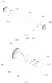
- FIG. 1 a schematic diagram of a three-dimensional structure of a cleaning brush proposed in the present disclosure is representatively shown.
- the cleaning brush proposed in the present disclosure is illustrated by taking an example of being applied to an intelligent cleaning robot.
- various modifications, additions, replacements, deletions or other changes are made to the following specific implementations, but these changes still fall within the scope of the principles of the cleaning brush proposed in the present disclosure.
- the cleaning brush proposed in the present disclosure mainly includes a shaft rod 100 (not shown in the figure), a cylindrical member 200 and two end members 300.
- FIG. 2 representatively shows a schematic three-dimensional exploded view of the cleaning brush
- FIG. 3 representatively shows a front view of FIG. 1
- FIG. 4 representatively shows a sectional view of a shaft side of FIG. 3
- FIG. 5 representatively shows a front view of FIG. 2
- FIG. 6 representatively shows a sectional view of a shaft side of FIG. 5
- FIG. 7 representatively shows a schematic diagram of a three-dimensional structure of the shaft rod 100 and the end members 300;
- FIG. 8 representatively shows an enlarged schematic diagram of an exploded state of part of the structure shown in FIG. 7 , and specifically shows an exploded state of one end member 300 and one first end 110 of the shaft rod.
- the shaft rod 100 has two first ends 110 opposite in an axial direction, that is, two ends of the shaft rod 100 are the first ends 110 respectively.
- the cylindrical member 200 coaxially sleeves the shaft rod 100 and is provided with two second ends 210 opposite in an axial direction, that is, two ends of the cylindrical member 200 are second ends 210 respectively.
- a brush piece is arranged on an outer surface of the cylindrical member 200.
- the two end members 300 are installed on the two first ends 110 of the shaft rod 100 respectively.
- Each end member 300 is provided with a blocking structure 310 capable of preventing an entanglement such as hairs and silk threads from excessively extending away from the cleaning brush.
- the end member 300 and the first end 110 corresponding to the end member 300 are provided with installation structures 400 matching each other respectively.
- the second end 210 of the cylindrical member 200 which corresponds to the end member 300, covers at least a portion of the end member 300, see a coverage area A shown in FIG. 4 for details.
- the cleaning brush proposed in the present disclosure includes at least one end member 300, the at least one end member 300 being installed on at least one first end 110 of the shaft rod 100.
- the second end 210 of the cylindrical member 200 which corresponds to the end member 300, may cover the first end 110, on which the end member 300 is installed.
- the first end 110 on which the end member 300 is installed is all located within a coverage range of the second end 210 corresponding to the first end, that is, the first end 110 does not extend out of the second end 210, and also the length of the shaft rod 100 is less than the length of the cylindrical member 200.
- the first end 110 on which the end member 300 is installed may also partially extend out of the coverage range of the corresponding second end 210, that is, the first end 110 may extend out of the coverage area A shown in FIG. 4 , but is not limited thereto in this implementation, as long as it is ensured that the second end 210 covers at least part of the end member 300.
- the blocking structure 310 of the end member 300 may be located outside the second end 210 of the cylindrical member 200, which corresponds to the end member 300. In other words, the blocking structure 310 of the end member 300 may be located outside the coverage area A shown in FIG. 4 .
- the installation structure 400 may include a guide hole 411 and a guide shaft 412.
- the guide hole 411 is coaxially formed in an end surface of the first end 110.
- the guide shaft 412 is connected to the end member 300 and used for being inserted into the guide hole 411.
- the guide shaft 412 and the guide hole 411 cooperate with each other by means of insertion, so that an axial guidance function and a radial limiting function are provided in the installation of the end members 300 and the shaft rod 100 in the present disclosure.
- the installation structure 400 may further include a guide sleeve 420.
- the guide sleeve 420 is arranged at an end of the end member 300 facing the shaft rod 100 and can sleeve the first end 110.
- a sidewall of the first end 110 is provided with a first limiting structure
- an inner wall of the guide sleeve 420 is provided with a second limiting structure matching the first limiting structure. Accordingly, the cleaning brush can achieve no relative rotation between the shaft rod 100 and the end members 300 by means of the cooperation between the first limiting structure and the second limiting structure.
- the installation structure 400 may include a guide hole 411, a guide shaft 412 and a guide sleeve 420 at the same time.
- the guide sleeve 420 may be arranged around the periphery of at least part of sections of the guide shaft 412 at intervals.
- the installation structure 400 may also include a guide hole 411 and a guide shaft 412 only, or a guide sleeve 420 alone, or realize installation and fixation of the end member 300 and the first end 110 of the shaft rod 100 by means of other structures.
- the distance L1 between the blocking structure 310 corresponding to the same first end 110 and an end of the guide sleeve 420 away from the end member 300 may account for more than 5%, e.g., 5%, 8%, 10% or 15% of the length L0 of the shaft rod 100.
- the cleaning brush of the present disclosure is characterized in that through the design that the guide sleeve 420 partially intervenes between the first end 110 and the second end 210, each end member 300 has a relatively large size (including a size of the guide sleeve 420), so as to increase a space of the end member 300 for an entanglement to wind, and further prevent the entanglement from being wound to the shaft rod 100.
- the design of a length relationship of the above related members is adopted, so that the length of a part of each end member 300 which matches the shaft rod 100 is extended, resulting in a size increase and easy processing and production.
- the first limiting structure may be a limiting groove 431
- the second limiting structure may be a limiting rib 432
- the limiting groove 431 matches the limiting rib 432 in shape. Accordingly, in the process of the guide sleeve 420 sleeving the first end 110 of the shaft rod 100, the limiting rib 432 and the limiting groove 431 cooperate with each other to provide guiding and limiting functions during the above installation process.
- the first limiting structure may also be a limiting rib 432
- the second limiting structure may also be a limiting groove 431.
- one of the first limiting structure and the second limiting structure may be a limiting rib 432, and the other may be a limiting groove 431 whose shape matches that of the limiting rib 432.
- the first limiting structure and the second limiting structure can also adopt other forms of limiting cooperation structures, but are not limited to this.
- the limiting rib 432 and the limiting groove 431 are in spiral shapes which match each other. Accordingly, in the disassembly and assembly processes of the end members 300 and the shaft rod 100, a relative displacement in an axial direction and a relative rotation in a circumferential direction exist therebetween.
- a spiral direction of the spiral limiting rib 432 and the spiral limiting groove 431 may be opposite to a rotation direction of the shaft rod 100.
- an outer wall of the guide sleeve 420 may be provided with at least one first assembly identifier 421 which can mark a rotation direction (i.e., the spiral direction of the limiting rib 432 and the limiting groove 431) when the end members 300 and the shaft rod 100 are assembled.
- the outer wall of the guide sleeve 420 may be provided with a deformation groove, which can prevent a shrinkage deformation of injection molded parts such as the guide sleeve 420 and the end members 300.
- the deformation groove may adopt a special shape, e.g., approximately a triangle, an arrow, etc., as the first assembly identifier 421 to mark the rotation direction when the end members 300 and the shaft rod 100 are assembled while preventing the shrinkage deformation.
- the limiting rib 432 may be arranged on an inner wall of the guide sleeve 420 through an integrated molding process in a case that the second limiting structure is the limiting rib 432.
- the limiting rib 432 may also be arranged on the inner wall of the guide sleeve 420 through other processes, e.g., by welding, or formed from part of the structure of the guide sleeve 420 by stamping, etc.
- a limiting groove 431 may be a groove formed in the inner wall of the guide sleeve 420 or a through groove penetrating through the guide sleeve 420, in a case that the second limiting structure is the limiting groove 431.
- the first end 110 may be provided with a plurality of first limiting structures, which is uniformly arranged at intervals in a circumferential direction of the shaft rod 100.
- the guide sleeve 420 may be provided with a plurality of the second limiting structures, which is uniformly arranged at intervals in a circumferential direction of the guide sleeve 420.
- the number of the limiting rib 432 may be one or more, and the number of the limiting ribs 432 is not greater than the number of the limiting grooves 431, but may be less than the number of the limiting grooves 431.
- the outer wall of the guide sleeve 420 may be provided with at least one second assembly identifier 422, and the at least one second assembly identifier 422 may correspond to at least one second limiting structure in position and accordingly is capable of marking a position of the at least one second limiting structure.
- the outer wall of the guide sleeve 420 may be provided with only one second assembly identifier 422 which corresponds to any second limiting structure; or the outer wall of the guide sleeve 420 may be provided with a plurality of second assembly identifiers 422 which correspond to the plurality of second limiting structures respectively.
- each end member 300 may be a blocking ring which may surround the outer circumference of the end member 300 and is a closed-loop structure.
- the end member 300 is installed on each of the two first ends 110 of the shaft rod 100.
- one of the two end members 300 is provided with a transmission structure 320, the transmission structure 320 being used to transmit a torque.
- the other of the two end members 300 is used for installation of a bearing structure 500.
- the end member 300 provided with the transmission structure 320 is connected to a driving mechanism of the cleaning device through the transmission structure 320, and the end member 300 on which the bearing structure 500 is installed is rotatably connected to other structures (e.g., a device body) of the cleaning device through the bearing structure 500.
- the driving side end cover rotates around the guide hole 411.
- the driving side end cover may move in an axial direction while rotating, thereby completing the entire assembly and disassembly of the end cover.
- the bearing side end cover may also be assembled and disassembled according to the same movement logic.
- the transmission structure 320 may include a columnar structure with a regularly polygonal cross-section, an axis of the columnar structure coinciding with an axis of the end member 300 and an axis of the shaft rod 100, the transmission structure being accordingly used to cooperate with an output end of a driving mechanism, e.g., a final-stage output gear of a gearbox.
- a driving mechanism e.g., a final-stage output gear of a gearbox.
- an end of the guide shaft 412 arranged on the end member 300 which is away from the shaft rod 100, extends out of the end member 300 and serves as a matching section 4121 matching the bearing structure 500; and the bearing structure 500 is detachably arranged on the matching section 4121 of the guide shaft 412.
- the matching section 4121 of the guide shaft 412 may be provided with a positioning groove 4122 in a circumferential direction.
- the outer diameter of the matching section 4121 is designed to be smaller than the outer diameter of other section of the guide shaft 412, such that the matching section 4121 forms the positioning groove 4122.
- the positioning groove 4122 cooperates with the bearing structure 500 by fixing each other's positions for preventing the bearing structure 500 from displacing.
- a friction structure 300 for example, but not limited to friction lines or fraction bulges, may be arranged on the end member 300, such that it is easier to screw the end member 300 during assembly.
- the cylindrical member 200 may be a flexible member or a rigid member.
- the brush piece may be arranged on the outer surface of the cylindrical member 200 by means of sticking, insertion and the like.
- the cylindrical member 200 is the flexible member, the brush piece and the cylindrical member 200 may also be integrally formed.
- the brush piece may also be a blade, bristles or in other forms.
- the first end is provided with a plurality of the first limiting structures, which is uniformly arranged at intervals in a circumferential direction of the shaft rod.
- the guide sleeve is provided with a plurality of the second limiting structures, which is uniformly arranged at intervals in a circumferential direction of the guide sleeve.
- the outer wall of the guide sleeve is provided with at least one second assembly identifier, the at least one second assembly identifier corresponding to the at least one second limiting structure in position and used for marking a position of the at least one second limiting structure.
- the blocking structure is a blocking ring, the blocking ring surrounding the outer circumference of the end member and being a closed-loop structure.
- the end member is installed on each of the two first ends of the shaft rod, one of the two end members is provided with a transmission structure, and the other is used for installation of a bearing structure.
- the transmission structure includes a columnar structure with a regularly polygonal cross-section, an axis of the columnar structure coinciding with an axis of the end member and an axis of the shaft rod; and the transmission structure is used to cooperate with an output end of a driving mechanism.
- one end of the guide shaft of one of the end members which is away from the shaft rod, extends out of the end member and serves as a matching section matching the bearing structure; and the bearing structure is detachably arranged on the matching section of the guide shaft.
- the matching section is provided with a positioning groove in a circumferential direction, the positioning groove cooperating with the bearing structure by fixing each other's positions to prevent the bearing structure from displacing.
- the cylindrical member may be a flexible member or a rigid member.
- the intelligent cleaning device proposed in the present disclosure includes a cleaning brush proposed in the present disclosure and detailed in the above implementations.
- the cleaning brush purposed by the present disclosure includes the shaft rod 100, the cylindrical member 200 and the end members 300.
- Each end member 300 is installed on the first end 110 of the shaft rod 100.
- Each end member 300 is provided with the blocking structure 310 for preventing an entanglement from excessively extending away from the cleaning brush.
- the end member 300 and the first end 110 are provided with installation structures 400 matching each other respectively.
- the second end 210 of the cylindrical member 200 which corresponds to the end member 300, covers at least a portion of the end member 300.
Landscapes
- Engineering & Computer Science (AREA)
- Mechanical Engineering (AREA)
- Cleaning In General (AREA)
- Brushes (AREA)
- Cleaning Implements For Floors, Carpets, Furniture, Walls, And The Like (AREA)
- Feeding Of Articles By Means Other Than Belts Or Rollers (AREA)
Applications Claiming Priority (2)
| Application Number | Priority Date | Filing Date | Title |
|---|---|---|---|
| CN202210022939.2A CN114247670B (zh) | 2022-01-10 | 2022-01-10 | 清洁刷及智能清洁设备 |
| PCT/CN2022/110958 WO2023130720A1 (zh) | 2022-01-10 | 2022-08-08 | 清洁刷及智能清洁设备 |
Publications (2)
| Publication Number | Publication Date |
|---|---|
| EP4464221A1 true EP4464221A1 (de) | 2024-11-20 |
| EP4464221A4 EP4464221A4 (de) | 2025-12-17 |
Family
ID=80799533
Family Applications (1)
| Application Number | Title | Priority Date | Filing Date |
|---|---|---|---|
| EP22918176.3A Pending EP4464221A4 (de) | 2022-01-10 | 2022-08-08 | Reinigungsbürste und intelligente reinigungsvorrichtung |
Country Status (6)
| Country | Link |
|---|---|
| EP (1) | EP4464221A4 (de) |
| JP (1) | JP7852059B2 (de) |
| KR (1) | KR20240129025A (de) |
| CN (2) | CN114247670B (de) |
| AU (1) | AU2022431360B2 (de) |
| WO (1) | WO2023130720A1 (de) |
Cited By (1)
| Publication number | Priority date | Publication date | Assignee | Title |
|---|---|---|---|---|
| EP4464222A4 (de) * | 2022-01-10 | 2025-12-17 | Beijing Roborock Technology Co Ltd | Reinigungsbürste und intelligente reinigungsvorrichtung |
Families Citing this family (5)
| Publication number | Priority date | Publication date | Assignee | Title |
|---|---|---|---|---|
| CN114247670B (zh) * | 2022-01-10 | 2023-07-18 | 北京石头世纪科技股份有限公司 | 清洁刷及智能清洁设备 |
| CN220327406U (zh) * | 2022-12-30 | 2024-01-12 | 北京石头世纪科技股份有限公司 | 清洁刷和自动清洁设备 |
| JP3253888U (ja) * | 2022-12-30 | 2025-12-08 | 北京石頭世紀科技股▲ふん▼有限公司 | 自動清掃装置 |
| CN116998954A (zh) * | 2022-12-30 | 2023-11-07 | 北京石头世纪科技股份有限公司 | 自动清洁设备 |
| CN220069620U (zh) * | 2022-12-30 | 2023-11-24 | 北京石头世纪科技股份有限公司 | 清洁刷及自动清洁设备 |
Family Cites Families (30)
| Publication number | Priority date | Publication date | Assignee | Title |
|---|---|---|---|---|
| JP2003080922A (ja) * | 2001-06-25 | 2003-03-19 | Calsonic Kansei Corp | モータの取付構造 |
| DE102006019458A1 (de) * | 2006-04-26 | 2007-10-31 | Jensen-Senking Gmbh | Durchlaufwaschmaschine und Waschverfahren |
| JP4164529B2 (ja) * | 2007-02-19 | 2008-10-15 | キヤノン株式会社 | 電子写真感光体ドラム |
| US8800107B2 (en) * | 2010-02-16 | 2014-08-12 | Irobot Corporation | Vacuum brush |
| CN111281266B (zh) * | 2011-04-29 | 2021-12-10 | 艾罗伯特公司 | 移动清洁机器人和自主覆盖机器人 |
| SG11201402550XA (en) * | 2011-12-02 | 2014-09-26 | Kao Corp | Cleaning tool |
| DE102012205269A1 (de) * | 2012-03-30 | 2013-10-02 | Invent Umwelt- Und Verfahrenstechnik Ag | Horizontalrührwerk |
| CN203493580U (zh) * | 2013-09-06 | 2014-03-26 | 深圳市银星智能科技股份有限公司 | 清洁刷和使用该清洁刷的清洁组件及地面清洁装置 |
| KR20150116133A (ko) * | 2014-04-04 | 2015-10-15 | 에이스전자(주) | 브러쉬 청소기 |
| CN203809169U (zh) * | 2014-04-24 | 2014-09-03 | 安徽江淮汽车股份有限公司 | 一种波纹管 |
| JP6186312B2 (ja) * | 2014-07-02 | 2017-08-23 | 日立アプライアンス株式会社 | 電気掃除機 |
| CN105361809B (zh) * | 2014-08-22 | 2018-03-09 | 莱克电气股份有限公司 | 吸尘器的滚刷装置 |
| US20160345792A1 (en) * | 2015-05-28 | 2016-12-01 | Neato Robotics, Inc. | Brush entanglement prevention apparatus in autonomous robotic vacuums |
| CN105982625B (zh) * | 2016-04-14 | 2019-07-09 | 北京小米移动软件有限公司 | 自动清洁设备及其清扫组件 |
| CN207356040U (zh) * | 2017-04-13 | 2018-05-15 | 苏州普发科技有限公司 | 一种吸尘器清洁头的刷棒 |
| JP2019159217A (ja) * | 2018-03-16 | 2019-09-19 | 京セラドキュメントソリューションズ株式会社 | 定着装置及び画像形成装置 |
| CN208892424U (zh) * | 2018-04-04 | 2019-05-24 | 天佑电器(苏州)有限公司 | 一种地刷组件及具有其的吸尘器 |
| CN209450440U (zh) * | 2018-07-12 | 2019-10-01 | 莱克电气股份有限公司 | 一种滚刷接头、滚刷装置及吸尘器 |
| KR102807469B1 (ko) * | 2019-08-21 | 2025-05-16 | 삼성전자주식회사 | 진공청소기 |
| JP7400288B2 (ja) * | 2019-09-23 | 2023-12-19 | 株式会社プロテリアル | 管継手および管の取り外し方法 |
| CN112741554B (zh) * | 2019-10-30 | 2024-07-09 | 苏州宝时得电动工具有限公司 | 清洁机器人 |
| JP2021122786A (ja) * | 2020-02-05 | 2021-08-30 | 三菱ケミカル・クリンスイ株式会社 | 浄水器 |
| CN112515551A (zh) * | 2020-09-29 | 2021-03-19 | 深圳市银星智能科技股份有限公司 | 防缠绕清洁滚刷及清洁机器人 |
| CN112587037B (zh) * | 2020-12-24 | 2025-08-08 | 珠海格力电器股份有限公司 | 滚刷组件及扫地机器人 |
| CN215016790U (zh) * | 2021-02-02 | 2021-12-07 | 深圳市云视机器人有限公司 | 清洁设备滚刷组件 |
| CN113876271A (zh) * | 2021-10-20 | 2022-01-04 | 永州雅力德科技有限公司 | 用于清洁设备的一体式滚刷 |
| CN113876270A (zh) * | 2021-10-20 | 2022-01-04 | 永州雅力德科技有限公司 | 用于清洁设备的新型滚刷 |
| CN114247670B (zh) * | 2022-01-10 | 2023-07-18 | 北京石头世纪科技股份有限公司 | 清洁刷及智能清洁设备 |
| CN217338427U (zh) * | 2022-01-10 | 2022-09-02 | 北京石头世纪科技股份有限公司 | 清洁刷及智能清洁设备 |
| CN217411582U (zh) * | 2022-01-10 | 2022-09-13 | 北京石头世纪科技股份有限公司 | 清洁刷及智能清洁设备 |
-
2022
- 2022-01-10 CN CN202210022939.2A patent/CN114247670B/zh active Active
- 2022-01-10 CN CN202310799315.6A patent/CN116602593A/zh active Pending
- 2022-08-08 EP EP22918176.3A patent/EP4464221A4/de active Pending
- 2022-08-08 KR KR1020247025705A patent/KR20240129025A/ko active Pending
- 2022-08-08 WO PCT/CN2022/110958 patent/WO2023130720A1/zh not_active Ceased
- 2022-08-08 JP JP2024541761A patent/JP7852059B2/ja active Active
- 2022-08-08 AU AU2022431360A patent/AU2022431360B2/en active Active
Cited By (1)
| Publication number | Priority date | Publication date | Assignee | Title |
|---|---|---|---|---|
| EP4464222A4 (de) * | 2022-01-10 | 2025-12-17 | Beijing Roborock Technology Co Ltd | Reinigungsbürste und intelligente reinigungsvorrichtung |
Also Published As
| Publication number | Publication date |
|---|---|
| WO2023130720A1 (zh) | 2023-07-13 |
| CN114247670B (zh) | 2023-07-18 |
| CN114247670A (zh) | 2022-03-29 |
| KR20240129025A (ko) | 2024-08-27 |
| JP7852059B2 (ja) | 2026-04-27 |
| JP2025502195A (ja) | 2025-01-24 |
| AU2022431360A1 (en) | 2024-08-15 |
| CN116602593A (zh) | 2023-08-18 |
| AU2022431360B2 (en) | 2026-02-05 |
| EP4464221A4 (de) | 2025-12-17 |
Similar Documents
| Publication | Publication Date | Title |
|---|---|---|
| EP4464221A1 (de) | Reinigungsbürste und intelligente reinigungsvorrichtung | |
| EP4464222A1 (de) | Reinigungsbürste und intelligente reinigungsvorrichtung | |
| CN217338427U (zh) | 清洁刷及智能清洁设备 | |
| US20230277022A1 (en) | Cleaning brush and intelligent cleaning device having the same | |
| CN104868691A (zh) | 步进致动器 | |
| WO2026081845A1 (zh) | 谐波减速器、机械臂和清洁设备 | |
| JP2004536718A (ja) | ねじ込みインサートを取り付ける工具としての予備巻取り装置 | |
| EP3767192B1 (de) | Lüfterbefestigungsanordnung mit einer hülsenanordnung zum kuppeln eines motors und eines lüfters einer klimaanlage | |
| JP2009261368A (ja) | 魚釣用リールおよびスリーブ状軸受 | |
| CN212726617U (zh) | 微电机转子及医用微电机 | |
| CN112440222B (zh) | 轴承外环装配工装 | |
| CN216504691U (zh) | 一种角度传感器装配用定位模块 | |
| CN224138873U (zh) | 一种电机定子绕线工装 | |
| CN215479393U (zh) | 一种晾衣机卷线结构与晾衣机 | |
| CN209150897U (zh) | 电动推杆 | |
| KR20200080121A (ko) | 스피닝 릴의 핸들 조립체 및 스피닝 릴 | |
| CN223785897U (zh) | 一种管状电机的行程头结构 | |
| CN223536773U (zh) | 夹物机天车的轴承套座 | |
| CN217231211U (zh) | 一种卷线机构及具有其的晾衣杆 | |
| CN116419901B (zh) | 片材卷绕轴 | |
| CN219221002U (zh) | 一种防松螺母、风机系统及吸油烟机 | |
| US20240423183A1 (en) | Line guide mechanism for spinning reel | |
| CN220373144U (zh) | 一种医疗器械用扭矩控制装置 | |
| CN217808019U (zh) | 一种多工位传动软轴钢丝的定位卷线轴 | |
| CN218517692U (zh) | 一种定模侧配合长度可调节的料缸结构 |
Legal Events
| Date | Code | Title | Description |
|---|---|---|---|
| STAA | Information on the status of an ep patent application or granted ep patent |
Free format text: STATUS: THE INTERNATIONAL PUBLICATION HAS BEEN MADE |
|
| PUAI | Public reference made under article 153(3) epc to a published international application that has entered the european phase |
Free format text: ORIGINAL CODE: 0009012 |
|
| STAA | Information on the status of an ep patent application or granted ep patent |
Free format text: STATUS: REQUEST FOR EXAMINATION WAS MADE |
|
| 17P | Request for examination filed |
Effective date: 20240808 |
|
| AK | Designated contracting states |
Kind code of ref document: A1 Designated state(s): AL AT BE BG CH CY CZ DE DK EE ES FI FR GB GR HR HU IE IS IT LI LT LU LV MC MK MT NL NO PL PT RO RS SE SI SK SM TR |
|
| DAV | Request for validation of the european patent (deleted) | ||
| DAX | Request for extension of the european patent (deleted) | ||
| A4 | Supplementary search report drawn up and despatched |
Effective date: 20251114 |
|
| RIC1 | Information provided on ipc code assigned before grant |
Ipc: A47L 11/24 20060101AFI20251110BHEP Ipc: A47L 11/40 20060101ALI20251110BHEP Ipc: B08B 11/00 20060101ALI20251110BHEP Ipc: A46B 13/00 20060101ALI20251110BHEP Ipc: A47L 9/04 20060101ALI20251110BHEP Ipc: B08B 1/12 20240101ALI20251110BHEP Ipc: B08B 1/34 20240101ALI20251110BHEP Ipc: A47L 11/00 20060101ALI20251110BHEP |