EP4459832A1 - Ladesteuerungsverfahren und ladesteuerungsvorrichtung und batteriepack damit - Google Patents
Ladesteuerungsverfahren und ladesteuerungsvorrichtung und batteriepack damit Download PDFInfo
- Publication number
- EP4459832A1 EP4459832A1 EP24172025.9A EP24172025A EP4459832A1 EP 4459832 A1 EP4459832 A1 EP 4459832A1 EP 24172025 A EP24172025 A EP 24172025A EP 4459832 A1 EP4459832 A1 EP 4459832A1
- Authority
- EP
- European Patent Office
- Prior art keywords
- internal state
- battery
- value
- charging
- charging current
- Prior art date
- Legal status (The legal status is an assumption and is not a legal conclusion. Google has not performed a legal analysis and makes no representation as to the accuracy of the status listed.)
- Pending
Links
Images


Classifications
-
- H—ELECTRICITY
- H02—GENERATION; CONVERSION OR DISTRIBUTION OF ELECTRIC POWER
- H02J—ELECTRIC POWER NETWORKS; CIRCUIT ARRANGEMENTS OR SYSTEMS FOR SUPPLYING OR DISTRIBUTING ELECTRIC POWER; SYSTEMS FOR STORING ELECTRIC ENERGY
- H02J7/00—Circuit arrangements for charging or discharging batteries or for supplying loads from batteries
- H02J7/90—Regulation of charging or discharging current or voltage
- H02J7/92—Regulation of charging or discharging current or voltage with prioritisation of loads or sources
-
- H—ELECTRICITY
- H02—GENERATION; CONVERSION OR DISTRIBUTION OF ELECTRIC POWER
- H02J—ELECTRIC POWER NETWORKS; CIRCUIT ARRANGEMENTS OR SYSTEMS FOR SUPPLYING OR DISTRIBUTING ELECTRIC POWER; SYSTEMS FOR STORING ELECTRIC ENERGY
- H02J7/00—Circuit arrangements for charging or discharging batteries or for supplying loads from batteries
- H02J7/90—Regulation of charging or discharging current or voltage
- H02J7/94—Regulation of charging or discharging current or voltage in response to battery current
-
- G—PHYSICS
- G01—MEASURING; TESTING
- G01R—MEASURING ELECTRIC VARIABLES; MEASURING MAGNETIC VARIABLES
- G01R31/00—Arrangements for testing electric properties; Arrangements for locating electric faults; Arrangements for electrical testing characterised by what is being tested not provided for elsewhere
- G01R31/36—Arrangements for testing, measuring or monitoring the electrical condition of accumulators or electric batteries, e.g. capacity or state of charge [SoC]
- G01R31/367—Software therefor, e.g. for battery testing using modelling or look-up tables
-
- G—PHYSICS
- G01—MEASURING; TESTING
- G01R—MEASURING ELECTRIC VARIABLES; MEASURING MAGNETIC VARIABLES
- G01R31/00—Arrangements for testing electric properties; Arrangements for locating electric faults; Arrangements for electrical testing characterised by what is being tested not provided for elsewhere
- G01R31/36—Arrangements for testing, measuring or monitoring the electrical condition of accumulators or electric batteries, e.g. capacity or state of charge [SoC]
- G01R31/382—Arrangements for monitoring battery or accumulator variables, e.g. SoC
- G01R31/3828—Arrangements for monitoring battery or accumulator variables, e.g. SoC using current integration
-
- H—ELECTRICITY
- H01—ELECTRIC ELEMENTS
- H01M—PROCESSES OR MEANS, e.g. BATTERIES, FOR THE DIRECT CONVERSION OF CHEMICAL ENERGY INTO ELECTRICAL ENERGY
- H01M10/00—Secondary cells; Manufacture thereof
- H01M10/42—Methods or arrangements for servicing or maintenance of secondary cells or secondary half-cells
- H01M10/44—Methods for charging or discharging
-
- H—ELECTRICITY
- H02—GENERATION; CONVERSION OR DISTRIBUTION OF ELECTRIC POWER
- H02J—ELECTRIC POWER NETWORKS; CIRCUIT ARRANGEMENTS OR SYSTEMS FOR SUPPLYING OR DISTRIBUTING ELECTRIC POWER; SYSTEMS FOR STORING ELECTRIC ENERGY
- H02J7/00—Circuit arrangements for charging or discharging batteries or for supplying loads from batteries
- H02J7/40—Circuit arrangements for charging or discharging batteries or for supplying loads from batteries characterised by the exchange of charge or discharge related data
-
- H—ELECTRICITY
- H02—GENERATION; CONVERSION OR DISTRIBUTION OF ELECTRIC POWER
- H02J—ELECTRIC POWER NETWORKS; CIRCUIT ARRANGEMENTS OR SYSTEMS FOR SUPPLYING OR DISTRIBUTING ELECTRIC POWER; SYSTEMS FOR STORING ELECTRIC ENERGY
- H02J7/00—Circuit arrangements for charging or discharging batteries or for supplying loads from batteries
- H02J7/40—Circuit arrangements for charging or discharging batteries or for supplying loads from batteries characterised by the exchange of charge or discharge related data
- H02J7/44—Circuit arrangements for charging or discharging batteries or for supplying loads from batteries characterised by the exchange of charge or discharge related data between battery management systems and power sources
-
- H—ELECTRICITY
- H02—GENERATION; CONVERSION OR DISTRIBUTION OF ELECTRIC POWER
- H02J—ELECTRIC POWER NETWORKS; CIRCUIT ARRANGEMENTS OR SYSTEMS FOR SUPPLYING OR DISTRIBUTING ELECTRIC POWER; SYSTEMS FOR STORING ELECTRIC ENERGY
- H02J7/00—Circuit arrangements for charging or discharging batteries or for supplying loads from batteries
- H02J7/80—Circuit arrangements for charging or discharging batteries or for supplying loads from batteries including monitoring or indicating arrangements
-
- H—ELECTRICITY
- H02—GENERATION; CONVERSION OR DISTRIBUTION OF ELECTRIC POWER
- H02J—ELECTRIC POWER NETWORKS; CIRCUIT ARRANGEMENTS OR SYSTEMS FOR SUPPLYING OR DISTRIBUTING ELECTRIC POWER; SYSTEMS FOR STORING ELECTRIC ENERGY
- H02J7/00—Circuit arrangements for charging or discharging batteries or for supplying loads from batteries
- H02J7/80—Circuit arrangements for charging or discharging batteries or for supplying loads from batteries including monitoring or indicating arrangements
- H02J7/84—Control of state of health [SOH]
-
- H—ELECTRICITY
- H02—GENERATION; CONVERSION OR DISTRIBUTION OF ELECTRIC POWER
- H02J—ELECTRIC POWER NETWORKS; CIRCUIT ARRANGEMENTS OR SYSTEMS FOR SUPPLYING OR DISTRIBUTING ELECTRIC POWER; SYSTEMS FOR STORING ELECTRIC ENERGY
- H02J7/00—Circuit arrangements for charging or discharging batteries or for supplying loads from batteries
- H02J7/875—Charging or discharging for charge maintenance, battery initiation or rejuvenation
-
- H—ELECTRICITY
- H02—GENERATION; CONVERSION OR DISTRIBUTION OF ELECTRIC POWER
- H02J—ELECTRIC POWER NETWORKS; CIRCUIT ARRANGEMENTS OR SYSTEMS FOR SUPPLYING OR DISTRIBUTING ELECTRIC POWER; SYSTEMS FOR STORING ELECTRIC ENERGY
- H02J7/00—Circuit arrangements for charging or discharging batteries or for supplying loads from batteries
- H02J7/90—Regulation of charging or discharging current or voltage
- H02J7/96—Regulation of charging or discharging current or voltage in response to battery voltage
-
- H—ELECTRICITY
- H02—GENERATION; CONVERSION OR DISTRIBUTION OF ELECTRIC POWER
- H02J—ELECTRIC POWER NETWORKS; CIRCUIT ARRANGEMENTS OR SYSTEMS FOR SUPPLYING OR DISTRIBUTING ELECTRIC POWER; SYSTEMS FOR STORING ELECTRIC ENERGY
- H02J7/00—Circuit arrangements for charging or discharging batteries or for supplying loads from batteries
- H02J7/90—Regulation of charging or discharging current or voltage
- H02J7/971—Regulation of charging or discharging current or voltage the charge cycle being controlled or terminated in response to non-electric parameters
- H02J7/975—Regulation of charging or discharging current or voltage the charge cycle being controlled or terminated in response to non-electric parameters in response to temperature
- H02J7/977—Regulation of charging or discharging current or voltage the charge cycle being controlled or terminated in response to non-electric parameters in response to temperature of the battery
-
- H—ELECTRICITY
- H01—ELECTRIC ELEMENTS
- H01M—PROCESSES OR MEANS, e.g. BATTERIES, FOR THE DIRECT CONVERSION OF CHEMICAL ENERGY INTO ELECTRICAL ENERGY
- H01M10/00—Secondary cells; Manufacture thereof
- H01M10/05—Accumulators with non-aqueous electrolyte
- H01M10/052—Li-accumulators
-
- H—ELECTRICITY
- H02—GENERATION; CONVERSION OR DISTRIBUTION OF ELECTRIC POWER
- H02J—ELECTRIC POWER NETWORKS; CIRCUIT ARRANGEMENTS OR SYSTEMS FOR SUPPLYING OR DISTRIBUTING ELECTRIC POWER; SYSTEMS FOR STORING ELECTRIC ENERGY
- H02J7/00—Circuit arrangements for charging or discharging batteries or for supplying loads from batteries
- H02J7/50—Circuit arrangements for charging or discharging batteries or for supplying loads from batteries acting upon multiple batteries simultaneously or sequentially
-
- Y—GENERAL TAGGING OF NEW TECHNOLOGICAL DEVELOPMENTS; GENERAL TAGGING OF CROSS-SECTIONAL TECHNOLOGIES SPANNING OVER SEVERAL SECTIONS OF THE IPC; TECHNICAL SUBJECTS COVERED BY FORMER USPC CROSS-REFERENCE ART COLLECTIONS [XRACs] AND DIGESTS
- Y02—TECHNOLOGIES OR APPLICATIONS FOR MITIGATION OR ADAPTATION AGAINST CLIMATE CHANGE
- Y02E—REDUCTION OF GREENHOUSE GAS [GHG] EMISSIONS, RELATED TO ENERGY GENERATION, TRANSMISSION OR DISTRIBUTION
- Y02E60/00—Enabling technologies; Technologies with a potential or indirect contribution to GHG emissions mitigation
- Y02E60/10—Energy storage using batteries
Definitions
- the present disclosure relates to a charging control method, and a charging control apparatus and a battery pack performing the same.
- a secondary battery differs from a primary battery in that charging and discharging can be repeated, whereas the primary battery only provides nonreversible conversion from chemical energy to electrical energy.
- a low-capacity secondary battery is used as a power supply device for small electronic devices, such as portable telephones, laptops computers, and camcorders, and a highcapacity secondary battery is used as a power supply device for hybrid vehicles and the like.
- a secondary battery cell may include an electrode assembly including a positive electrode, a negative electrode, a separator interposed between the positive electrode and the negative electrode, a case for accommodating the electrode assembly therein, and an electrode terminal electrically connected to the electrode assembly.
- An electrolyte solution is injected into the case to enable charging and discharging of the battery cell through an electrochemical reaction of the positive electrode, the negative electrode, and the electrolyte solution.
- a shape of the case such as cylindrical or rectangular, may depend on an application of the battery cell.
- Battery cells may be connected in series and/or parallel to form a battery module having high energy density.
- a battery pack may include one or more of these battery modules according to required specifications.
- a constant current (CC) method As a charging method of a secondary battery cell, a constant current (CC) method, a constant voltage (CV) method, a constant power (CP) method, and a constant current and constant voltage (CCCV) method are mainly used. These methods are charging control methods based on external conditions of the secondary battery, such as current, voltage, and power, and may have limitations in improving deterioration due to charging of the secondary battery.
- CC constant current
- CV constant voltage
- CP constant power
- CCCV constant current and constant voltage
- the deterioration caused by charging may be one of the main factors that reduce the lifespan of a secondary battery. Therefore, to increase the lifespan of the secondary battery, it may be desirable to suppress deterioration due to charging.
- As a method of reducing deterioration due to charging there is a method of charging the secondary battery with a low rate current while maintaining the temperature of the secondary battery at an appropriate temperature.
- a charging technology capable of reducing or minimizing charging deterioration of a battery while charging at a high rate of current may be desirable.
- the present disclosure attempts to provide a charging control method, and a charging control apparatus and a battery pack performing the same while being capable of high rate charging and capable of improving degradation due to charging.
- a charging control apparatus may include a storage device configured to store a battery model, a detection device configured to detect an external state value including at least one of a voltage, a current, and a temperature of a battery, and a control device configured to control a charging current by using feedback loop control in which at least one internal state value of the battery is estimated by using the battery model and the external state value, and configured to determine a first charging current value based on the estimated at least one internal state value.
- the control device may be configured to determine the first charging current value such that the at least one internal state value converges to a target value, and may be configured to control the charging current based on the first charging current value.
- the target value may correspond to a boundary value between a high degradation region and a low degradation region divided with reference to an internal state of the battery.
- the internal state may include an anode potential, wherein the target value includes a value that is greater than 0.
- the internal state may include a cathode potential, wherein the target value includes a value that is less than an operating region voltage of a battery cell of the battery.
- the battery model may include an electrochemical model for modelling an internal state of a secondary battery cell having one or more specifications that are substantially similar to those of the battery.
- the control device may be configured to estimate a plurality of internal state values corresponding to a plurality of internal state parameters of the battery by using the battery model and the external state value, may be configured to determine, for each of the plurality of internal state parameters, a current range so that the corresponding internal state value converges to the corresponding target value, and may be configured to determine a current value satisfying all of the current ranges corresponding to the plurality of internal state parameters as the first charging current value.
- the control device may be configured to estimate a plurality of internal state values corresponding to a plurality of internal state parameters of the battery by using the battery model and the external state value, may be configured to determine, for each of the plurality of internal state parameters, a second charging current value so that the corresponding internal state value converges to the corresponding target value, and may be configured to determine the first charging current value by sequentially referring to the second charging current values corresponding to the plurality of internal state parameters according to a processing sequence determined based on priorities assigned to the plurality of the internal state parameters.
- the control device may include one or more controllers capable of the feedback loop control, wherein the controller is configured to perform at least one control function of proportional (P) control, integral (I) control, and differential (D) control.
- P proportional
- I integral
- D differential
- the control device may be configured to communicate with a charger, and may be configured to control a charging current by transferring the first charging current value to the charger.
- a battery pack may include a battery and the charging control apparatus.
- the control device may include a battery management system of the battery pack.
- a charging control method of a battery pack may include detecting an external state value including at least one of a voltage, a current, and a temperature of a battery, estimating at least one internal state value indicating an internal state of the battery by using a battery model and the external state value, determining a first charging current value based on the estimated at least one internal state value, controlling a charging current of a charger based on the first charging current value, and repeatedly performing the detecting, the estimating, the determining, and the controlling, while charging the battery pack.
- the first charging current value may be determined such that the at least one internal state value converges to a target value.
- the target value may correspond to a boundary value between a high degradation region and a low degradation region divided with reference to the internal state of the battery.
- the internal state may include at least one of an anode potential, a cathode potential, and a cathode concentration.
- the battery model may include an electrochemical model for modelling an internal state of a secondary battery cell having one or more specifications that are substantially similar to those of the battery.
- the estimating may include estimating a plurality of internal state values corresponding to a plurality of internal state parameters of the battery by using the battery model and the external state value.
- the determining the first charging current value may include determining, for each of the plurality of internal state parameters, a current range so that the corresponding internal state value converges to the corresponding target value, and determining a current value satisfying all of the current ranges corresponding to the plurality of internal state parameters as the first charging current value.
- the determining the first charging current may include determining, for each of the plurality of internal state parameters, a second charging current value so that the corresponding internal state value converges to the corresponding target value, and determining the first charging current value by sequentially referring to the second charging current values corresponding to the plurality of internal state parameters according to a processing sequence determined based on priorities assigned to the plurality of the internal state parameters.
- the charging speed may be increased while reducing or maximally suppressing the degradation of the battery pack.
- connection indicates electrical connection unless explicitly described to be direct connection, and "directly connected/directly coupled,” or “directly on,” refers to one component directly connecting or coupling another component, or being on another component, without an intermediate component.
- expressions such as "at least one of,” or “any one of,” or “one or more of” when preceding a list of elements modify the entire list of elements and do not modify the individual elements of the list.
- “at least one of X, Y, and Z,” “at least one of X, Y, or Z,” “at least one selected from the group consisting of X, Y, and Z,” and “at least one selected from the group consisting of X, Y, or Z” may be construed as X only, Y only, Z only, any combination of two or more of X, Y, and Z, such as, for instance, XYZ, XYY, YZ, and ZZ, or any variation thereof.
- the expression such as “at least one of A and B” and “at least one of A or B” may include A, B, or A and B.
- “or” generally means “and/or,” and the term “and/or” includes any and all combinations of one or more of the associated listed items.
- the expression such as “A and/or B” may include A, B, or A and B.
- first,” “second,” “third,” etc. may be used herein to describe various elements, components, regions, layers and/or sections, these elements, components, regions, layers and/or sections should not be limited by these terms. These terms do not correspond to a particular order, position, or superiority, and are used only used to distinguish one element, member, component, region, area, layer, section, or portion from another element, member, component, region, area, layer, section, or portion. Thus, a first element, component, region, layer or section described below could be termed a second element, component, region, layer or section, without departing from the scope of the present disclosure.
- first element may not require or imply the presence of a second element or other elements.
- first,” second,” etc. may also be used herein to differentiate different categories or sets of elements.
- first, second, etc. may represent “first-category (or first-set),” “second-category (or second-set),” etc., respectively.
- a specific process order may be performed differently from the described order.
- two consecutively described processes may be performed substantially at the same time or performed in an order opposite to the described order.
- the term “substantially,” “about,” “approximately,” and similar terms are used as terms of approximation and not as terms of degree, and are intended to account for the inherent deviations in measured or calculated values that would be recognized by those of ordinary skill in the art. For example, “substantially” may include a range of +/- 5 % of a corresponding value. “About” or “approximately,” as used herein, is inclusive of the stated value and means within an acceptable range of deviation for the particular value as determined by one of ordinary skill in the art, considering the measurement in question and the error associated with measurement of the particular quantity (i.e., the limitations of the measurement system).
- each block, unit, and/or module may be implemented by dedicated hardware, or a combination of dedicated hardware that performs some functions and a processor (for example, one or more programmed microprocessors and related circuits) that performs a function different from those of the dedicated hardware.
- the block, unit, and/or module may be physically separated into two or more interact individual blocks, units, and/or modules without departing from the scope of the present disclosure.
- the block, unit and/or module may be physically combined into more complex blocks, units, and/or modules without departing from the scope of the present disclosure.
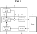
- FIG. 1 schematically illustrates a charging system of a battery pack according to one or more embodiments.
- a charging system of a battery pack 1a includes a charging control apparatus included in the battery pack 1a, and includes a charger 2 external to the battery pack 1a.
- the battery pack 1a includes a battery 10 and the charging control apparatus.
- the battery 10 may include at least one secondary battery cell.
- the charging control apparatus may include a storage device 21, a detection device 22, and a control device 23.
- the storage device 21 may store programs for operation of the charging control apparatus, and may store various data processed by the charging control apparatus.
- the storage device 21 may store an electrochemical model (hereinafter, referred to as a "battery model") for modeling an internal state of the secondary battery cell having the same specifications as the battery cell of the battery 10.
- the storage device 21 subdivides the external state (for example, current, cell voltage, temperature, and/or the like) of the secondary battery cell.
- the storage device 21 may store the battery model in the form of a table for mapping the internal state (for example, cathode potential, anode potential, cathode concentration, and/or the like) of the secondary battery cell as calculated for each state by using the battery model.
- the storage device 21 may store the battery model of the secondary battery cell in the form of a function that receives a state value representing the external state of the secondary battery cell (for example, current, voltage, temperature, and/or the like). Also, the storage device 21 may output a state value representing the internal state (for example, cathode potential, anode potential, cathode concentration, and/or the like) of the secondary battery cell.
- a state value representing the external state of the secondary battery cell for example, current, voltage, temperature, and/or the like.
- the storage device 21 may output a state value representing the internal state (for example, cathode potential, anode potential, cathode concentration, and/or the like) of the secondary battery cell.
- the storage device 21 may store an internal state target value that serves as a reference for controlling the internal state of the battery 10 as not to progress to a region in which the charging degradation is high.
- a region (hereinafter, referred to as a "low degradation region") having a relatively low level of charging degradation
- another region hereinafter, referred to as a "high degradation region” having a relatively high level of charging degradation, with reference to the internal state of the battery 10, may be confirmed in advance based on simulation, experiment, or the like of the secondary battery cell having the same or similar specifications as the secondary battery cell of the battery 10.
- the internal state target value stored in the storage device 21 may be defined as an internal state value immediately before the internal state of the battery 10 progresses to the high degradation region based on the low degradation region and the high degradation region that have been previously identified.
- the internal state value may be a boundary value for distinguishing the low degradation region from the high degradation region.
- the internal state target value may be set to be a value greater than about 0.
- the internal state target value may be set to be a value that is less than operating region voltage of battery cell.
- the internal state target value may be set to be lower than about 30% of an upper or maximum concentration value.
- the low degradation region and the high degradation region of the battery 10 may be varied according to the degree of degradation of the battery 10.
- the storage device 21 may subdivide the degree of degradation of the battery 10 based on a lifespan model of the battery 10. Also, the storage device 21 may map and store the internal state target value that serves as the reference for controlling the internal state of the battery 10 as not to progress to the high degradation region, with respect to respective degrees of degradation.
- the detection device 22 may monitor the state of the battery cell of the battery 10 to continuously detect an external state of the battery 10, such as voltage (e.g., cell voltage), current, temperature, and/or the like.
- the detection device 22 may transfer a state value/external state value S1 of the detected external state to the control device 23 if the external state of the battery 10 is detected.
- the control device 23 may estimate the internal state of the battery 10 based on the external state value S1 received from the detection device 22 and based on the battery model (e.g., pre-stored battery model).
- the control device 23 may control a charging current of the charger 2 in real time by a feedback loop method such that the estimated internal state value of the battery 10 converges to the internal state target value S3 (e.g., pre-stored internal state target value).
- the control device 23 may include a battery model portion 231 and a controller 232.
- the battery model portion 231 may estimate the internal state of the battery 10 corresponding to the received external state value S1 by using the battery model (e.g., pre-stored battery model).
- the battery model is generated by modeling electrochemical characteristics of one secondary battery cell.
- the battery model portion 231 may estimate an internal state representing internal states of the battery cells of the battery 10 by using an average external state value (average cell voltage, average current, average temperature, and/or the like) of the plurality of battery cells, or the external state value (cell voltage, current, temperature, and/or the like) of a representative cell of the battery cells. For example, the battery model portion 231 may select a weak cell having a greatest degree of degradation among the battery cells as the representative cell, and may estimate the internal state of the battery 10 by inputting the external state value detected with respect to the selected weak cell.
- the battery model portion 231 may select a weak cell having a greatest degree of degradation among the battery cells as the representative cell, and may estimate the internal state of the battery 10 by inputting the external state value detected with respect to
- the battery model portion 231 may select one of internal state parameters that may be estimated by using the battery model as a control parameter for controlling the charging current, and may output the internal state value S2 of the selected the control parameter to the controller 232.
- the battery model portion 231 may select a parameter that may identify the degree of charging degradation of the battery cell, such as the cathode potential, the anode potential, the cathode concentration, and/or the like among the internal state parameters of the battery 10 that may be estimated by using the battery model, as the control parameter.
- the controller 232 may continuously receive the internal state value S2 corresponding to the control parameter from the battery model portion 231, and based on this, may control the charging current in real time by a feedback loop method such that the internal state value of the battery 10 converges to the internal state target value S3 (e.g., the predetermined internal state target value).
- the controller 232 if the internal state value S2 corresponding to the control parameter is received from the battery model portion 231, the controller 232 repeatedly performs control of the charging current in real time such that the received internal state value S2 converges to the corresponding internal state target value S3.
- the controller 232 may maintain the internal state of the battery 10 at the state immediately preceding entry into the high degradation region.
- the controller 232 may communicate with the charger 2 through controller area network (CAN) communication or the like. If the value of the charging current is determined such that the internal state value S2 of the control parameter converges to the corresponding internal state target value S3, the controller 232 may control the charging current that is applied to the battery 10 from the charger 2 in real time by transferring the determined current value to the charger 2 in real time.
- CAN controller area network
- the control device 23 may be implemented by a battery management system (BMS) of the battery pack 1a.
- BMS battery management system
- the controller 232 may be implemented by one or more controller that is capable of feedback loop control, and that is configured to perform at least one control function of proportional (P) control, integral (I) control, and/or differential (D) control.
- FIG. 2 schematically illustrates a charging control method of a battery pack according to one or more embodiments.
- the charging control method of FIG. 2 may be performed by the charging control device 23 described with reference to FIG. 1 .
- the control device 23 may obtain the external state value of the battery cell of the battery 10 (e.g., current, cell voltage, temperature, and/or the like) through the detection device 22.
- the external state value of the battery cell of the battery 10 e.g., current, cell voltage, temperature, and/or the like
- the control device 23 estimates the internal state value corresponding to the control parameter of the battery 10 (e.g., the anode potential, the cathode potential, the cathode concentration, and/or the like) based on the battery model.
- the control parameter of the battery 10 e.g., the anode potential, the cathode potential, the cathode concentration, and/or the like
- control device 23 determines, at operation S14, the charging current value of the charger 2. This may be such that the estimated internal state value of the control parameter converges to the corresponding internal state target value.
- control device 23 controls the charging current of the charger 2 in real time.
- control device 23 may maintain the internal state of the battery cell at the state immediately preceding the high degradation region.
- FIG. 3 schematically illustrates a charging system of a battery pack according to one or more other embodiments.
- FIG. 3 schematically illustrates a charging system of a battery pack according to one or more other embodiments.
- duplicate descriptions of the same components as those constituting the charging system of FIG. 1 may be omitted.
- a charging system of a battery pack 1b includes the charging control apparatus included in a battery pack 1b, and includes the charger 2 external to the battery pack 1b.
- the battery pack 1b includes the battery 10 and the charging control apparatus.
- the battery 10 may include at least one secondary battery cell.
- the charging control apparatus include the storage device 21, the detection device 22, and the control device 23.
- the storage device 21 may store the battery model in the form of a table or function.
- the battery model is an electrochemical model for modelling an internal state of the secondary battery cell having the same specification as the battery cell of the battery 10.
- the storage device 21 may store the internal state target value that serves as the reference for controlling the internal state of the battery 10 during charging as not to progress to the region in which the charging degradation is high.
- the storage device 21 may map and may store the corresponding internal state target values with respect to a plurality of the control parameters selected from among the internal state parameters that may be estimated by using the battery model.
- the storage device 21 may subdivide the degree of degradation of the battery 10 based on a lifespan model of the battery 10, and may map and store the internal state target values of the plurality of the control parameters with respect to respective degrees of degradation.
- the detection device 22 may continuously detect the external state of the battery 10 (e.g., voltage/cell voltage, current, temperature, and/or the like), and may transfer the detected external state value S1 to the control device 23.
- the external state of the battery 10 e.g., voltage/cell voltage, current, temperature, and/or the like
- the control device 23 estimates the internal state of the battery 10 based on the external state value S1 received from the detection device 22 and based on the battery model (e.g., pre-stored battery model), and controls the charging current of the charger 2 in real time by a feedback loop method such that the estimated internal state value of the battery 10 converges to the internal state value S3 (e.g., pre-stored internal state target value).
- the battery model e.g., pre-stored battery model
- the control device 23 may include the battery model portion 231, and a plurality of controllers 232-1, 232-2, and 232-3, and the charging current controller 233.
- the battery model portion 231 estimates the internal state of the battery 10 corresponding to the received the external state value S1 by using the battery model (e.g., pre-stored battery model). If the battery 10 includes the plurality of battery cells, the battery model portion 231 may estimate the internal state of the battery 10 by using the average of the external state value (e.g., average cell voltage, average current, average temperature, and/or the like) of the plurality of battery cells, or by using the external state value (e.g., cell voltage, current, temperature, and/or the like) of a representative cell selected from the plurality of battery cells.
- the battery model e.g., pre-stored battery model
- the battery model portion 231 may select the plurality of the control parameters among the internal state parameters that may be estimated by using the battery model as the control parameter for controlling the charging current, and may output the internal state values S21, S22, and S23 of the selected the control parameters to the plurality of controllers 232-1, 232-2, and 232-3, respectively.
- the battery model portion 231 may select the cathode potential, the anode potential, and the cathode concentration among the internal state parameters of the battery 10, which may be estimated by using the battery model as the control parameter.
- Each of the controllers 232-1, 232-2, and 232-3 may continuously receive the internal state values S21, S22, and S23 corresponding to the respective control parameters from the battery model portion 231, and based thereon, determines the charging current value for converging the internal state value of the battery 10 to the internal state target values S31, S32, and S33 (e.g., predetermined internal state target values).
- Each of the controllers 232-1, 232-2, and 232-3 may transfer such determined information of the charging current value to the charging current controller 233.
- the charging current value transferred from each of the controllers 232-1, 232-2, and 232-3 to the charging current controller 233 may include a single value, or may include information with respect to a current range (e.g., predetermined current range) defined by an upper limit value and by a lower limit value.
- a current range e.g., predetermined current range
- the charging current controller 233 controls, in real time, the charging current of the charger 2 based on the information.
- the charging current controller 233 may determine the charging current value concurrently or substantially simultaneously satisfying the charging current value received from each of the controllers 232-1, 232-2, and 232-3, and may control the charging current of the charger 2 by using the charging current value. In one or more embodiments, the charging current controller 233 may detect an overlapping portion between current regions indicated by the respective charging current values received from the controllers 232-1, 232-2, and 232-3, and may determine the charging current value for controlling the charger 2 in the detected overlapping portion.
- the charging current controller 233 may assign different priorities with respect to the plurality of the control parameters. For example, the charging current controller 233 may assign a higher priority to the control parameter as the sensitivity of the control parameter with respect to a change in the charging current increases.
- the charging current controller 233 may determine a processing sequence of the charging current values respectively received from the controllers 232-1, 232-2, and 232-3 based on the priority, and may control the charging current of the charger 2 in a serial control method in which the charging current values are sequentially referenced according to the determined processing sequence.
- the charging current controller 233 may communicate with the charger 2 through CAN communication or the like.
- the charging current controller 233 may control the charging current applied to the battery 10 from the charger 2 in real time by transferring the finally determined charging current value to the charger 2 in real time.
- the aforementioned control device 23 may be implemented by a battery management system (BMS) of the battery pack 1b.
- BMS battery management system
- the plurality of controllers 232-1, 232-2, and 232-3 may be implemented by one or more controllers that are capable of feedback loop control, and that are configured to perform at least one control function of proportional (P) control, integral (I) control, and/or differential (D) control.
- FIG. 4 schematically illustrates a charging control method of a battery pack according to one or more other embodiments.
- the charging control method of FIG. 4 may be performed by the charging control device 23 described with reference to FIG. 3 .
- the control device 23 obtains the external state value of the battery cell of the battery 10 (e.g., current, cell voltage, temperature, and/or the like) through the detection device 22.
- the external state value of the battery cell of the battery 10 e.g., current, cell voltage, temperature, and/or the like
- the control device 23 estimates the internal state value corresponding to each of the plurality of the control parameters of the battery 10 (for example, the anode potential, the cathode potential, and the cathode concentration) based on the battery model.
- control device 23 determines the charging current values with respect to the plurality of the control parameters, such that the estimated internal state value converges to the corresponding internal state target value with respect to each of the plurality of the control parameters.
- the control device 23 determines the final charging current value to be used in controlling the charging current of the charger 2 based on the charging current values.
- the control device 23 may determine, as the final charging current value, the charging current value that concurrently or substantially simultaneously satisfies all of the plurality of the control parameters. In one or more embodiments, the control device 23 may detect an overlapping portion between current regions indicated by the charging current values corresponding to the respective control parameters, and may determine the final charging current value for controlling the charger 2 in the detected overlapping portion.
- the control device 23 may sequentially select the charging current values corresponding to the respective control parameters as the final charging current value for controlling the charger 2.
- the control device 23 may control the charging current of the charger 2 in real time by using this final charging current value.
- control device 23 may maintain the internal state of the battery cell to the state immediately preceding entering into the high degradation region.
- FIG. 5 is a drawing for describing an aspect of a charging control method according to one or more embodiments.
- the conventional step charging method performed in a feedforward method may have a disadvantage in that it may be difficult to finely control the charging current.
- the charging current in a state immediately prior to proceeding to the high degradation region, as in one or more embodiments, there is an aspect of shortening, or reducing, the charging time.
- the charging current is controlled in the region that is lower than the charging current value calculated by the feedback loop method by a margin (e.g., predetermined margin), as in one or more other embodiments, the peak charging current may be lowered even if the same charging time elapses as in the step charging method, and thus, in the long term, the longer lifespan may be secured in comparison with the step charging method.
- An electronic or electrical device and/or any other related device or component according to the embodiments of the present disclosure that are described herein may be implemented by using any suitable hardware, firmware (e.g., an application-specific integrated circuit), software, or a combination of software, firmware, and hardware.
- various components of these devices may be disposed on one integrated circuit (IC) chip or on separate IC chips.
- various components of these devices may be implemented on a flexible printed circuit film (TCP), a tape carrier package (TCP), a printed circuit board (PCB), or on one substrate.
- TCP flexible printed circuit film
- TCP tape carrier package
- PCB printed circuit board
- the electrical connections or interconnections described in the present specification may be implemented by wires or conductive elements, e.g., on a PCB or on other types of circuit carriers.
- the conductive element may include, e.g., metallization, such as surface metallization, and/or pins, and may include conductive polymers or ceramics. Electrical energy may also be transmitted via a wireless connection using, e.g., electromagnetic radiation or light.
- various components of these devices may be executed on one or more processors to perform various functions described herein and within one or more computing devices, and may be processes or threads that execute computer program instructions and may interact with other system components.
- Computer program instructions are stored in a memory that can be implemented in a computing device using a standard memory device, such as, e.g., a random access memory (RAM).
- the computer program instructions may also be stored on other non-transitory computer readable media, e.g., CD-ROMs, flash drives, and/or the like.
- battery pack 2 charger 10: battery 21: storage device 22: detection device 23: control device 231: the battery model portion 232, 232-1, 232-2, 232-3: controller 233: the charging current controller
Landscapes
- Engineering & Computer Science (AREA)
- Power Engineering (AREA)
- General Physics & Mathematics (AREA)
- Physics & Mathematics (AREA)
- General Chemical & Material Sciences (AREA)
- Electrochemistry (AREA)
- Chemical Kinetics & Catalysis (AREA)
- Chemical & Material Sciences (AREA)
- Manufacturing & Machinery (AREA)
- Secondary Cells (AREA)
- Charge And Discharge Circuits For Batteries Or The Like (AREA)
- Health & Medical Sciences (AREA)
- General Health & Medical Sciences (AREA)
- Medical Informatics (AREA)
Applications Claiming Priority (1)
| Application Number | Priority Date | Filing Date | Title |
|---|---|---|---|
| KR1020230057217A KR20240160420A (ko) | 2023-05-02 | 2023-05-02 | 충전 제어 방법, 및 이를 수행하는 충전 제어 장치 및 배터리 팩 |
Publications (1)
| Publication Number | Publication Date |
|---|---|
| EP4459832A1 true EP4459832A1 (de) | 2024-11-06 |
Family
ID=90880440
Family Applications (1)
| Application Number | Title | Priority Date | Filing Date |
|---|---|---|---|
| EP24172025.9A Pending EP4459832A1 (de) | 2023-05-02 | 2024-04-23 | Ladesteuerungsverfahren und ladesteuerungsvorrichtung und batteriepack damit |
Country Status (5)
| Country | Link |
|---|---|
| US (1) | US20240372391A1 (de) |
| EP (1) | EP4459832A1 (de) |
| JP (1) | JP7735366B2 (de) |
| KR (1) | KR20240160420A (de) |
| CN (1) | CN118899924A (de) |
Citations (4)
| Publication number | Priority date | Publication date | Assignee | Title |
|---|---|---|---|---|
| US20200335993A1 (en) * | 2017-10-24 | 2020-10-22 | Samsung Electronics Co., Ltd. | Method and apparatus for charging battery |
| US20210013731A1 (en) * | 2018-12-06 | 2021-01-14 | Lg Chem, Ltd. | Charging Apparatus And Method Of Secondary Battery |
| US20210053450A1 (en) * | 2017-12-29 | 2021-02-25 | Samsung Electronics Co., Ltd. | Battery charging method and apparatus |
| US20220115875A1 (en) * | 2020-10-13 | 2022-04-14 | Samsung Electronics Co., Ltd. | Method and apparatus for charging battery |
Family Cites Families (4)
| Publication number | Priority date | Publication date | Assignee | Title |
|---|---|---|---|---|
| JP5152529B2 (ja) * | 2009-12-09 | 2013-02-27 | 三菱自動車工業株式会社 | 内部抵抗推定装置 |
| JP7013987B2 (ja) * | 2018-03-22 | 2022-02-01 | トヨタ自動車株式会社 | ハイブリッド車 |
| KR102871577B1 (ko) * | 2019-09-04 | 2025-10-17 | 삼성전자주식회사 | 배터리 충전 장치 및 방법 |
| JP7566694B2 (ja) * | 2021-07-14 | 2024-10-15 | 株式会社東芝 | 二次電池の管理方法、二次電池の充電方法、二次電池の管理装置、二次電池の管理システム、及び、二次電池の管理プログラム |
-
2023
- 2023-05-02 KR KR1020230057217A patent/KR20240160420A/ko active Pending
- 2023-09-28 JP JP2023167847A patent/JP7735366B2/ja active Active
-
2024
- 2024-01-04 US US18/404,781 patent/US20240372391A1/en active Pending
- 2024-04-23 EP EP24172025.9A patent/EP4459832A1/de active Pending
- 2024-04-30 CN CN202410539618.9A patent/CN118899924A/zh active Pending
Patent Citations (4)
| Publication number | Priority date | Publication date | Assignee | Title |
|---|---|---|---|---|
| US20200335993A1 (en) * | 2017-10-24 | 2020-10-22 | Samsung Electronics Co., Ltd. | Method and apparatus for charging battery |
| US20210053450A1 (en) * | 2017-12-29 | 2021-02-25 | Samsung Electronics Co., Ltd. | Battery charging method and apparatus |
| US20210013731A1 (en) * | 2018-12-06 | 2021-01-14 | Lg Chem, Ltd. | Charging Apparatus And Method Of Secondary Battery |
| US20220115875A1 (en) * | 2020-10-13 | 2022-04-14 | Samsung Electronics Co., Ltd. | Method and apparatus for charging battery |
Also Published As
| Publication number | Publication date |
|---|---|
| JP2024160918A (ja) | 2024-11-15 |
| CN118899924A (zh) | 2024-11-05 |
| JP7735366B2 (ja) | 2025-09-08 |
| US20240372391A1 (en) | 2024-11-07 |
| KR20240160420A (ko) | 2024-11-11 |
Similar Documents
| Publication | Publication Date | Title |
|---|---|---|
| US20160156202A1 (en) | Battery pack and method for controlling the same | |
| US11084397B2 (en) | Power supply system for vehicle with multiple operating voltages | |
| EP3316440B1 (de) | Batteriesystem mit integriertem ausgleich und verfahren zum ausgleich eines batteriesystems | |
| US20190379092A1 (en) | Method and system for validating a temperature sensor in a battery cell | |
| EP3620321B1 (de) | Stromversorgungssystem | |
| EP3579006B1 (de) | Validierung eines temperatursensors einer batteriezelle | |
| US11391781B2 (en) | SOC estimating apparatus and method | |
| KR20210039267A (ko) | 배터리 시스템 및 배터리 시스템 제어 방법 | |
| CN113904005A (zh) | 用于在低温下最大化充电功率的阳极电位的在线测量 | |
| EP4459832A1 (de) | Ladesteuerungsverfahren und ladesteuerungsvorrichtung und batteriepack damit | |
| US20240204537A1 (en) | Battery management method, battery management device and battery pack performing the same | |
| EP3316385A1 (de) | Batteriesystem mit intern angetriebener echtzeituhr, stromversorgungsschaltung für eine echtzeituhr und verfahren zum betreiben einer echtzeituhr eines batteriesystems | |
| US20240339853A1 (en) | Device and method for controlling charging of battery pack | |
| EP4451505A1 (de) | Ladesteuerungsverfahren und ladesteuerungsvorrichtung und batteriepack damit | |
| US20240322333A1 (en) | Battery replacement system and method | |
| EP4498477A2 (de) | Schutzverfahren für batteriepack sowie schutzvorrichtung und batteriepack damit | |
| US20240322263A1 (en) | Battery pack | |
| US20250015602A1 (en) | Battery system and charge/discharge control method thereof | |
| US20240332988A1 (en) | Battery pack | |
| US20260087437A1 (en) | Apparatus and method for predicting quality of product, and computer program | |
| US20250226479A1 (en) | Apparatus and method for battery cooling control | |
| EP4560336A1 (de) | Vorrichtung und verfahren zum nachweis von abnormal verschlechterten zellen | |
| EP4186746A1 (de) | Batteriesystem und verfahren zum betrieb davon | |
| KR20250068315A (ko) | 공정 인자 설계 시스템 및 그 방법 | |
| JP2025178125A (ja) | バッテリー過充電防止装置および方法、バッテリーパック |
Legal Events
| Date | Code | Title | Description |
|---|---|---|---|
| PUAI | Public reference made under article 153(3) epc to a published international application that has entered the european phase |
Free format text: ORIGINAL CODE: 0009012 |
|
| STAA | Information on the status of an ep patent application or granted ep patent |
Free format text: STATUS: REQUEST FOR EXAMINATION WAS MADE |
|
| 17P | Request for examination filed |
Effective date: 20240423 |
|
| AK | Designated contracting states |
Kind code of ref document: A1 Designated state(s): AL AT BE BG CH CY CZ DE DK EE ES FI FR GB GR HR HU IE IS IT LI LT LU LV MC ME MK MT NL NO PL PT RO RS SE SI SK SM TR |