EP3620321B1 - Stromversorgungssystem - Google Patents
Stromversorgungssystem Download PDFInfo
- Publication number
- EP3620321B1 EP3620321B1 EP18193097.5A EP18193097A EP3620321B1 EP 3620321 B1 EP3620321 B1 EP 3620321B1 EP 18193097 A EP18193097 A EP 18193097A EP 3620321 B1 EP3620321 B1 EP 3620321B1
- Authority
- EP
- European Patent Office
- Prior art keywords
- node
- low voltage
- voltage
- power supply
- switching element
- Prior art date
- Legal status (The legal status is an assumption and is not a legal conclusion. Google has not performed a legal analysis and makes no representation as to the accuracy of the status listed.)
- Active
Links
- 238000004146 energy storage Methods 0.000 claims description 16
- 230000000295 complement effect Effects 0.000 claims description 10
- 239000007858 starting material Substances 0.000 claims description 6
- 238000010586 diagram Methods 0.000 description 10
- 238000000034 method Methods 0.000 description 6
- 238000005259 measurement Methods 0.000 description 5
- 230000009977 dual effect Effects 0.000 description 4
- 238000004891 communication Methods 0.000 description 3
- 238000004590 computer program Methods 0.000 description 3
- 230000006870 function Effects 0.000 description 3
- 238000001465 metallisation Methods 0.000 description 3
- 230000015556 catabolic process Effects 0.000 description 2
- 238000006243 chemical reaction Methods 0.000 description 2
- 229920001940 conductive polymer Polymers 0.000 description 2
- 238000006731 degradation reaction Methods 0.000 description 2
- 239000008151 electrolyte solution Substances 0.000 description 2
- 238000009434 installation Methods 0.000 description 2
- 230000007257 malfunction Effects 0.000 description 2
- 238000004519 manufacturing process Methods 0.000 description 2
- 239000002253 acid Substances 0.000 description 1
- OJIJEKBXJYRIBZ-UHFFFAOYSA-N cadmium nickel Chemical compound [Ni].[Cd] OJIJEKBXJYRIBZ-UHFFFAOYSA-N 0.000 description 1
- 239000003990 capacitor Substances 0.000 description 1
- 230000001413 cellular effect Effects 0.000 description 1
- 239000000919 ceramic Substances 0.000 description 1
- 239000002322 conducting polymer Substances 0.000 description 1
- 239000004020 conductor Substances 0.000 description 1
- 230000003247 decreasing effect Effects 0.000 description 1
- 230000001419 dependent effect Effects 0.000 description 1
- 238000007599 discharging Methods 0.000 description 1
- 230000000694 effects Effects 0.000 description 1
- 238000003487 electrochemical reaction Methods 0.000 description 1
- 230000005670 electromagnetic radiation Effects 0.000 description 1
- 230000014509 gene expression Effects 0.000 description 1
- 230000002427 irreversible effect Effects 0.000 description 1
- 238000012986 modification Methods 0.000 description 1
- 230000004048 modification Effects 0.000 description 1
- 238000012544 monitoring process Methods 0.000 description 1
- 230000002085 persistent effect Effects 0.000 description 1
- 230000003068 static effect Effects 0.000 description 1
- 239000000126 substance Substances 0.000 description 1
- 239000000758 substrate Substances 0.000 description 1
- 238000012546 transfer Methods 0.000 description 1
Images

Classifications
-
- B—PERFORMING OPERATIONS; TRANSPORTING
- B60—VEHICLES IN GENERAL
- B60L—PROPULSION OF ELECTRICALLY-PROPELLED VEHICLES; SUPPLYING ELECTRIC POWER FOR AUXILIARY EQUIPMENT OF ELECTRICALLY-PROPELLED VEHICLES; ELECTRODYNAMIC BRAKE SYSTEMS FOR VEHICLES IN GENERAL; MAGNETIC SUSPENSION OR LEVITATION FOR VEHICLES; MONITORING OPERATING VARIABLES OF ELECTRICALLY-PROPELLED VEHICLES; ELECTRIC SAFETY DEVICES FOR ELECTRICALLY-PROPELLED VEHICLES
- B60L3/00—Electric devices on electrically-propelled vehicles for safety purposes; Monitoring operating variables, e.g. speed, deceleration or energy consumption
- B60L3/0092—Electric devices on electrically-propelled vehicles for safety purposes; Monitoring operating variables, e.g. speed, deceleration or energy consumption with use of redundant elements for safety purposes
-
- B—PERFORMING OPERATIONS; TRANSPORTING
- B60—VEHICLES IN GENERAL
- B60L—PROPULSION OF ELECTRICALLY-PROPELLED VEHICLES; SUPPLYING ELECTRIC POWER FOR AUXILIARY EQUIPMENT OF ELECTRICALLY-PROPELLED VEHICLES; ELECTRODYNAMIC BRAKE SYSTEMS FOR VEHICLES IN GENERAL; MAGNETIC SUSPENSION OR LEVITATION FOR VEHICLES; MONITORING OPERATING VARIABLES OF ELECTRICALLY-PROPELLED VEHICLES; ELECTRIC SAFETY DEVICES FOR ELECTRICALLY-PROPELLED VEHICLES
- B60L3/00—Electric devices on electrically-propelled vehicles for safety purposes; Monitoring operating variables, e.g. speed, deceleration or energy consumption
- B60L3/0023—Detecting, eliminating, remedying or compensating for drive train abnormalities, e.g. failures within the drive train
- B60L3/0046—Detecting, eliminating, remedying or compensating for drive train abnormalities, e.g. failures within the drive train relating to electric energy storage systems, e.g. batteries or capacitors
-
- B—PERFORMING OPERATIONS; TRANSPORTING
- B60—VEHICLES IN GENERAL
- B60L—PROPULSION OF ELECTRICALLY-PROPELLED VEHICLES; SUPPLYING ELECTRIC POWER FOR AUXILIARY EQUIPMENT OF ELECTRICALLY-PROPELLED VEHICLES; ELECTRODYNAMIC BRAKE SYSTEMS FOR VEHICLES IN GENERAL; MAGNETIC SUSPENSION OR LEVITATION FOR VEHICLES; MONITORING OPERATING VARIABLES OF ELECTRICALLY-PROPELLED VEHICLES; ELECTRIC SAFETY DEVICES FOR ELECTRICALLY-PROPELLED VEHICLES
- B60L53/00—Methods of charging batteries, specially adapted for electric vehicles; Charging stations or on-board charging equipment therefor; Exchange of energy storage elements in electric vehicles
- B60L53/20—Methods of charging batteries, specially adapted for electric vehicles; Charging stations or on-board charging equipment therefor; Exchange of energy storage elements in electric vehicles characterised by converters located in the vehicle
- B60L53/24—Using the vehicle's propulsion converter for charging
-
- B—PERFORMING OPERATIONS; TRANSPORTING
- B60—VEHICLES IN GENERAL
- B60L—PROPULSION OF ELECTRICALLY-PROPELLED VEHICLES; SUPPLYING ELECTRIC POWER FOR AUXILIARY EQUIPMENT OF ELECTRICALLY-PROPELLED VEHICLES; ELECTRODYNAMIC BRAKE SYSTEMS FOR VEHICLES IN GENERAL; MAGNETIC SUSPENSION OR LEVITATION FOR VEHICLES; MONITORING OPERATING VARIABLES OF ELECTRICALLY-PROPELLED VEHICLES; ELECTRIC SAFETY DEVICES FOR ELECTRICALLY-PROPELLED VEHICLES
- B60L58/00—Methods or circuit arrangements for monitoring or controlling batteries or fuel cells, specially adapted for electric vehicles
- B60L58/10—Methods or circuit arrangements for monitoring or controlling batteries or fuel cells, specially adapted for electric vehicles for monitoring or controlling batteries
- B60L58/18—Methods or circuit arrangements for monitoring or controlling batteries or fuel cells, specially adapted for electric vehicles for monitoring or controlling batteries of two or more battery modules
- B60L58/20—Methods or circuit arrangements for monitoring or controlling batteries or fuel cells, specially adapted for electric vehicles for monitoring or controlling batteries of two or more battery modules having different nominal voltages
-
- B—PERFORMING OPERATIONS; TRANSPORTING
- B60—VEHICLES IN GENERAL
- B60L—PROPULSION OF ELECTRICALLY-PROPELLED VEHICLES; SUPPLYING ELECTRIC POWER FOR AUXILIARY EQUIPMENT OF ELECTRICALLY-PROPELLED VEHICLES; ELECTRODYNAMIC BRAKE SYSTEMS FOR VEHICLES IN GENERAL; MAGNETIC SUSPENSION OR LEVITATION FOR VEHICLES; MONITORING OPERATING VARIABLES OF ELECTRICALLY-PROPELLED VEHICLES; ELECTRIC SAFETY DEVICES FOR ELECTRICALLY-PROPELLED VEHICLES
- B60L2210/00—Converter types
- B60L2210/10—DC to DC converters
- B60L2210/12—Buck converters
-
- B—PERFORMING OPERATIONS; TRANSPORTING
- B60—VEHICLES IN GENERAL
- B60L—PROPULSION OF ELECTRICALLY-PROPELLED VEHICLES; SUPPLYING ELECTRIC POWER FOR AUXILIARY EQUIPMENT OF ELECTRICALLY-PROPELLED VEHICLES; ELECTRODYNAMIC BRAKE SYSTEMS FOR VEHICLES IN GENERAL; MAGNETIC SUSPENSION OR LEVITATION FOR VEHICLES; MONITORING OPERATING VARIABLES OF ELECTRICALLY-PROPELLED VEHICLES; ELECTRIC SAFETY DEVICES FOR ELECTRICALLY-PROPELLED VEHICLES
- B60L2240/00—Control parameters of input or output; Target parameters
- B60L2240/40—Drive Train control parameters
- B60L2240/54—Drive Train control parameters related to batteries
- B60L2240/547—Voltage
-
- B—PERFORMING OPERATIONS; TRANSPORTING
- B60—VEHICLES IN GENERAL
- B60Y—INDEXING SCHEME RELATING TO ASPECTS CROSS-CUTTING VEHICLE TECHNOLOGY
- B60Y2200/00—Type of vehicle
- B60Y2200/90—Vehicles comprising electric prime movers
- B60Y2200/91—Electric vehicles
-
- Y—GENERAL TAGGING OF NEW TECHNOLOGICAL DEVELOPMENTS; GENERAL TAGGING OF CROSS-SECTIONAL TECHNOLOGIES SPANNING OVER SEVERAL SECTIONS OF THE IPC; TECHNICAL SUBJECTS COVERED BY FORMER USPC CROSS-REFERENCE ART COLLECTIONS [XRACs] AND DIGESTS
- Y02—TECHNOLOGIES OR APPLICATIONS FOR MITIGATION OR ADAPTATION AGAINST CLIMATE CHANGE
- Y02T—CLIMATE CHANGE MITIGATION TECHNOLOGIES RELATED TO TRANSPORTATION
- Y02T10/00—Road transport of goods or passengers
- Y02T10/60—Other road transportation technologies with climate change mitigation effect
- Y02T10/70—Energy storage systems for electromobility, e.g. batteries
-
- Y—GENERAL TAGGING OF NEW TECHNOLOGICAL DEVELOPMENTS; GENERAL TAGGING OF CROSS-SECTIONAL TECHNOLOGIES SPANNING OVER SEVERAL SECTIONS OF THE IPC; TECHNICAL SUBJECTS COVERED BY FORMER USPC CROSS-REFERENCE ART COLLECTIONS [XRACs] AND DIGESTS
- Y02—TECHNOLOGIES OR APPLICATIONS FOR MITIGATION OR ADAPTATION AGAINST CLIMATE CHANGE
- Y02T—CLIMATE CHANGE MITIGATION TECHNOLOGIES RELATED TO TRANSPORTATION
- Y02T10/00—Road transport of goods or passengers
- Y02T10/60—Other road transportation technologies with climate change mitigation effect
- Y02T10/7072—Electromobility specific charging systems or methods for batteries, ultracapacitors, supercapacitors or double-layer capacitors
-
- Y—GENERAL TAGGING OF NEW TECHNOLOGICAL DEVELOPMENTS; GENERAL TAGGING OF CROSS-SECTIONAL TECHNOLOGIES SPANNING OVER SEVERAL SECTIONS OF THE IPC; TECHNICAL SUBJECTS COVERED BY FORMER USPC CROSS-REFERENCE ART COLLECTIONS [XRACs] AND DIGESTS
- Y02—TECHNOLOGIES OR APPLICATIONS FOR MITIGATION OR ADAPTATION AGAINST CLIMATE CHANGE
- Y02T—CLIMATE CHANGE MITIGATION TECHNOLOGIES RELATED TO TRANSPORTATION
- Y02T10/00—Road transport of goods or passengers
- Y02T10/60—Other road transportation technologies with climate change mitigation effect
- Y02T10/72—Electric energy management in electromobility
-
- Y—GENERAL TAGGING OF NEW TECHNOLOGICAL DEVELOPMENTS; GENERAL TAGGING OF CROSS-SECTIONAL TECHNOLOGIES SPANNING OVER SEVERAL SECTIONS OF THE IPC; TECHNICAL SUBJECTS COVERED BY FORMER USPC CROSS-REFERENCE ART COLLECTIONS [XRACs] AND DIGESTS
- Y02—TECHNOLOGIES OR APPLICATIONS FOR MITIGATION OR ADAPTATION AGAINST CLIMATE CHANGE
- Y02T—CLIMATE CHANGE MITIGATION TECHNOLOGIES RELATED TO TRANSPORTATION
- Y02T90/00—Enabling technologies or technologies with a potential or indirect contribution to GHG emissions mitigation
- Y02T90/10—Technologies relating to charging of electric vehicles
- Y02T90/14—Plug-in electric vehicles
Definitions
- the present invention relates to a power supply system, particularly to a power supply battery system for an electric vehicle comprising a 48 V board net and a 12 V board net with redundant power supply for the 12 V board net.
- the power supply system of the present invention thus provides a limp home functionality for an electric vehicle.
- a rechargeable or secondary battery differs from a primary battery in that it can be repeatedly charged and discharged, while the latter provides only an irreversible conversion of chemical to electrical energy.
- Low-capacity rechargeable batteries are used as power supply for small electronic devices, such as cellular phones, notebook computers and camcorders, while high-capacity rechargeable batteries are used as the power supply for hybrid vehicles and the like.
- rechargeable batteries include an electrode assembly including a positive electrode, a negative electrode, and a separator interposed between the positive and negative electrodes, a case receiving the electrode assembly, and an electrode terminal electrically connected to the electrode assembly.
- An electrolyte solution is injected into the case in order to enable charging and discharging of the battery via an electrochemical reaction of the positive electrode, the negative electrode, and the electrolyte solution.
- the shape of the case e.g. cylindrical or rectangular, depends on the battery's intended purpose.
- Rechargeable batteries may be used as a battery module formed of a plurality of unit battery cells coupled in series and/or in parallel so as to provide a high energy density, e.g. for motor driving of a hybrid vehicle. That is, the battery module is formed by interconnecting the electrode terminals of the plurality of unit battery cells depending on a required amount of power and in order to realize a high-power rechargeable battery, e.g. for an electric vehicle.
- One or more battery modules are mechanically and electrically integrated, equipped with a thermal management system and set up for communication with one or more electrical consumers in order to form a battery system.
- a battery system For monitoring, controlling and/or setting of the aforementioned parameters a battery system usually comprises a battery management unit (BMU) and/or a battery management system (BMS).
- BMU battery management unit
- BMS battery management system
- control units may be an integral part of the battery system and disposed within a common housing or may be part of a remote control unit communicating with the battery system via a suitable communication bus. In both cases, the control unit communicates with the electrical consumers via a suitable communication bus, e.g. a CAN or SPI interface.
- the electric engine of electric vehicles may be supplied by a high voltage battery system, e.g. a 48 V battery system.
- the 48 V battery system is connected to a 48 V board net that may comprise electronic control units (ECUs) powered by the 48 V battery system.
- the 48 V battery system is usually charged by a electric generator (combined starter generator), which is therefore also a part of the high voltage board net.
- the electric vehicles may further comprise a 12 V board net that might be related to security relevant functions.
- an ECU of a power steering system or an ECU of an antiskid system may be integrated in the 12 V board net.
- the 12 V board net may comprise a 12 V battery system, e.g. a lead-acid based 12 V battery, that may be charged by the 48 V board net via a DC/DC converter.
- the DC/DC converter interconnected between the 48 V battery and the 12 V battery may provide an operating voltage to the 12 V board net in case of failure of the 12 V battery.
- the DC/DC converter acting as redundant power supply has to be designed to fulfil high functional safety standards, such as e.g. ISO26262. In order to meet these safety measures, the complexity and thus the costs for the DC/DC converter have to be increased drastically.
- EP 2587618 A2 discloses a car power source apparatus and vehicle equipped with the power source apparatus.
- US 6323608 B1 discloses a dual voltage battery for a motor vehicle.
- EP 3360719 A1 discloses a dual power supply system for a vehicle.
- the production costs, weight and installation space requirements of the power supply system shall be decreased compared to the prior art.
- any security relevant function related to at least one of the board nets of the electric vehicle shall be guaranteed in a redundant manner.
- a power supply system for an electric vehicle comprises a plurality of stacked battery cells that are interconnected between a first stack node and a second stack node and that are configured to provide a first operation voltage for supplying a high voltage board net of the electric vehicle.
- the high voltage board net spans between the first and the second stack node.
- the plurality of stacked battery cells may further comprise battery cells connected in parallel between the first terminal and the second terminal.
- a plurality of submodules, each comprising a plurality of cells connected in parallel may be connected in series between the first and second stack node.
- the added voltage of all battery cells connected in series between the first and second stack node applies between the first stack node and the second stack node.
- a voltage between 36 V and 52 V, particularly preferred of 48 V applies between the first stack node and the second stack node of the power supply system.
- the power supply system further comprises a low voltage battery that is interconnected between the second stack node and a low voltage node and is configured to output a second operation voltage for supplying a low voltage board net of the electric vehicle.
- the low voltage battery may be a Nickel Cadmium battery or a lead accumulator and/or may supply a 12 V board net of the electric vehicle. Hence, the low voltage battery may supply an operation voltage of 12 V.
- the low voltage board net spans between the second stack node and the low voltage node. However, in principal the low voltage board net could also span between the first stack node and the low voltage node.
- the second stack node is connected to ground, i.e. is the low voltage node of the stacked battery cells.
- a step-down converter is interconnected between the first stack node and the second stack node and is configured to output a third operation voltage to the low voltage node for charging the low voltage battery.
- the step-down converter receives the voltage output by the plurality of stacked battery cells and outputs a reduced voltage thereof to the low voltage node.
- the DC/DC converter is one of a buck converter, a forward converter, and a flyback converter.
- the converter is one of a full bridge converter, a buck-boost converter and a push-pull converter.
- the DC/DC converter is configured for converting the first voltage (input voltage) to the third voltage (output voltage).
- the power supply system of the present invention further comprises a an intermediate node dividing the plurality of stacked battery cells in a first subset of battery cells (first sub-stack) and a second subset of battery cells (second sub-stack).
- first sub-stack a first subset of battery cells
- second sub-stack a second subset of battery cells
- the added voltage of all battery cells connected in series between the first stack node and the intermediate node applies between the first stack node and the intermediate node
- the added voltage of all battery cells connected in series between the intermediate node and the second stack node applies between the intermediate node and the second stack node.
- the first subset and the second subset of battery cells may comprise the same amount or different amounts of stacked battery cells connected in series between the respective nodes.
- the nominal output voltages of the first and second subset of battery cells may be the same or different.
- the battery cells of the first sub-stack may have a different capacity than the battery cells of the second sub-stack.
- the intermediate node is connected to the low voltage node via a first switching element and a conductive path between the intermediate node and the low voltage node is set to be either opened or closed.
- the power supply system of the present invention further comprises a control unit that is configured to detect the terminal voltage of the low voltage battery and to set the first switching element conductive depending on the detected terminal voltage.
- the control unit is configured to set the first switching element either conductive or non-conductive based on the terminal voltage of the low voltage battery.
- the control unit may be integrated in a control unit of the battery system of the stacked battery cells, the low voltage battery or in an electric vehicle comprising the power supply system of the invention.
- the control unit may also be an individual component of the power supply system.
- the power supply system of the invention can advantageously supply a high voltage board net and a low voltage board net of an electric vehicle.
- a high voltage battery stack and a step-down converter By supporting the low voltage board net via a high voltage battery stack and a step-down converter, via a low voltage battery or via a second sub-stack of the high voltage battery stack, an improved redundancy in supplying the security relevant low-voltage board net is achieved.
- controlling the conductivity of the first switching element based on the terminal voltage of the low voltage battery allows for freely setting the voltage provided between the intermediate node and the second stack node and to the low voltage board net via the low voltage node.
- an electric vehicle comprising the power supply system of the invention can be brought into a safe state in reaction to a malfunction or degradation of the low voltage battery without an interruption of the safety relevant 12 V board and can thus "limp home".
- the DC/DC step down converter is not safety critical anymore and no additional measures and costs have to be considered for the step-down converter. Further, no additional costs arise with respect to the high voltage battery stack, which can be exemplarily a stock 48 V battery system without further modification for 12 V safety supply.
- the third operation voltage is less or equal than the second operation voltage.
- the voltage supplied by the step-down converter to the low-voltage board net is less or equal, particularly preferred equal, to the voltage supplied by the low voltage battery.
- a fourth operation voltage provided by the second subset of battery cells is in between the second operation voltage and the third operation voltage.
- the fourth operation voltage preferably exceeds the third operation voltage without exceeding the second operation voltage.
- the second, third and fourth operation voltages are equal. Hence, the performance of the low voltage board net is guaranteed without any compromise.
- the control unit is configured to set the first switching element conductive if the detected terminal voltage is less than a first predetermined voltage threshold.
- the first predetermined voltage threshold may be less or equal than the second operation voltage.
- the first predetermined voltage threshold is in between 50% and 100% of the second operation voltage, preferably in between 60% and 95%, 70% and 90%, or 80% and 85% of the second operation voltage.
- the control unit is configured to set the first switching element non-conductive if the detected terminal voltage is more than a second predetermined voltage threshold.
- the first predetermined voltage threshold is lower than at least one of the second to fourth operation voltage.
- the first predetermined voltage threshold is lower than each of the of the second to fourth operation voltages.
- at least some and preferably all of the operation voltages are not limited by the choice of the first predetermined voltage threshold. This is achieved by controlling the first switching element solely in dependence of the terminal voltage of the low voltage battery cell and not the voltage in the low or high voltage board net.
- the step-down converter comprises a first input node that is connected to the first stack node and a second input node that is connected to the second stack node.
- the first input node is at the same electric potential as the first stack node and the second input node is at the same electric potential as the second stack node.
- a second switching element and an energy storage element are connected in series between the first input node and the low voltage node.
- the second switching element is interconnected between the first input node and the energy storage element.
- a third switching element is interconnected between the second input node and a first converter node, wherein the first converter node is electrically connected between the second switching element and the energy storage element.
- the step-down converter preferably is a buck converter, particularly if an inductance is used as an energy storage element.
- a capacitor can be used as an energy storage element and hence in the context of the present application also a charge pump may be used as a step-down converter.
- the use of an inductance is particularly preferred.
- the step-down converter comprises a rectifying element interconnected between the energy storage element and the low voltage node, wherein the rectifying element is configured to suppress a current from the low voltage node to the step-down converter.
- the rectifying element advantageously allows for suppressing cross-talk from the low voltage board net to the high voltage board net.
- the rectifying element is a diode and by such passive element switching noise is advantageously reduced.
- the step-down converter is further configured to output the third operation voltage to the intermediate node for transferring energy from the first subset of battery cells to the second subset of battery cells.
- This configuration allows for balancing the first subset and the second subset of battery cells. Therein, a voltage that exceeds the voltage applied to the intermediate node is applied to the step-down converter's output. Thus, a current flows into the intermediate node and thus the first subset of battery cells becomes less discharged or even charged. Hence, even though the control unit is exclusively supplied by the first subset of battery cells if the first switching element is set conductive no persistent misbalance between the first and second subset of cells is caused.
- the step-down converter preferably comprises a second converter node that is electrically connected between the low voltage node and the energy storage element and a fourth switching element that is electrically connected between the second converter node and the intermediate node.
- the step-down converter comprises a fifth switching element that is electrically connected between the second converter node and the low voltage node.
- the step-down converter preferably comprises a further rectifying element interconnected between the intermediate node and the second converter node and configured for suppressing a current from the intermediate node to the step-down converter.
- the power supply system can be operated in a first operation mode, wherein the high voltage board net is operated by the stacked battery cells and the low voltage board net is operated by the low voltage battery and/or the step-down converter.
- the low voltage battery may be charged by the step-down converter.
- the power supply system can be operated in a second operation mode, wherein the high voltage board net is operated by the stacked battery cells and the low voltage board net is operated by the second sub-stack via the conductive first switching element.
- the power supply system can be operated in a third operation mode, wherein the step-down converter is used for balancing the first and second sub-stack and/or charging the low voltage battery.
- the third operation mode may be performed in an idle state of an electric vehicle comprising the power supply system.
- charging of the low-voltage battery via the step-down converter occurs, while the low voltage board net is operated by the second sub-stack via the conductive first switching element.
- the low voltage battery is preferably interconnected between the second stack node and the second converter node.
- the first rectifying element is interconnected between the low voltage node and the low voltage battery and configured for suppressing a current from the low voltage board net to the low voltage battery.
- the low voltage board net is operable via the second sub-stack if the low voltage battery is discharged, e.g., during winter, while the low voltage battery is charged.
- the control unit preferably is further configured to control the conductivity of at least one, preferably all, of the second to fifth switching element.
- a first pair of complementary transistors may be used for the second and third switching element and/or a second pair of complementary transistors may be is used for the fourth and fifth switching element.
- the conductivity states of the second and third switching element should be complementary, using complementary transistors allow setting these conductivity states with a single control signal.
- the conductivity states of the fourth and fifth switching element could be complementary using complementary transistors also allow setting these conductivity states with a single control signal.
- the first and second rectifying elements are realized by switching elements. Particularly, the first and second rectifying element is provided by the fourth and fifth switching element, respectively.
- the control unit of the power supply system is configured for setting the duty cycle of at least one switching element for performing the balancing of the sub-stacks.
- Another aspect of the present invention is directed to a vehicle comprising a power supply system according to the invention, as described above, and further comprising at least one first load that is interconnected between the first stack node and the second stack node and at least one second load that is interconnected between the second stack node and the low voltage node.
- the vehicle comprises a power supply system according to the invention, as described above, and further comprises a starter generator that is interconnected between the first stack node and the second stack node.
- the first load has an operation voltage of about 48 V and the second load has an operation voltage of about 12 V.
- the power supply system is operated in one of a first, second, third or fourth operation mode.
- the first operation mode the high voltage board net is operated by the stacked battery cells and the low voltage board net is operated by the low voltage battery and/or the step-down converter.
- the low voltage battery may be charged by the step-down converter.
- the second operation mode the high voltage board net is operated by the stacked battery cells and the low voltage board net is operated by the second sub-stack via the conductive first switching element.
- the step-down converter is used for balancing the first and second sub-stack and/or charging the low voltage battery.
- the third operation mode may be performed in an idle state of an electric vehicle comprising the power supply system.
- charging of the low-voltage battery via the step-down converter occurs, while the low voltage board net is operated by the second sub-stack via the conductive first switching element. Then, the low voltage board net is operable via the second sub-stack if the low voltage battery is discharged, e.g. during winter, while the low voltage battery is charged for later supply.
- the term “and/or” includes any and all combinations of one or more of the associated listed items. Further, the use of “may” when describing embodiments of the present invention refers to "one or more embodiments of the present invention.” In the following description of embodiments of the present invention, the terms of a singular form may include plural forms unless the context clearly indicates otherwise. It will be understood that although the terms “first” and “second” are used to describe various elements, these elements should not be limited by these terms. These terms are only used to distinguish one element from another element. For example, a first element may be named a second element and, similarly, a second element may be named a first element, without departing from the scope of the present invention. Expressions such as "at least one of,” when preceding a list of elements, modify the entire list of elements and do not modify the individual elements thereof.
- the term “substantially,” “about,” and similar terms are used as terms of approximation and not as terms of degree, and are intended to account for the inherent deviations in measured or calculated values that would be recognized by those of ordinary skill in the art. Further, if the term “substantially” is used in combination with a feature that could be expressed using a numeric value, the term “substantially” denotes a range of +/- 5% of the value centered on the value.
- FIG. 1 schematically illustrates a power supply system of an electric vehicle according to the prior art.
- the power supply system according to the prior art comprises a 48 V battery system 1 and an additional 12 V battery system 2 that is external to the 48 V battery system 1.
- the 48 V battery system 1 is charged by a starter generator 7 and the 12 V battery system 2 is charged by the 48 V battery system 1 via an additional DC/DC converter 3 that is external to the battery systems 1, 2.
- the 48 V battery system 1 is connected via a 48 V board net to 48 V supplied loads, e.g. to 48 V supplied ECU 5, and the 12 V battery system 2 is connected to 12 V supplied loads, e.g. to 12 V supplied ECU 6.
- a voltage variable load e.g.
- a voltage variable ECU 4 with internal DC/DC converter may be connected to the 48 V battery system 1 and the 12 V battery system 2.
- the dual power supply system according to the prior art comprises separate 48 V battery system, 12 V battery system and DC/DC converter and hence requires a lot of installation space, is heavy and high in production costs.
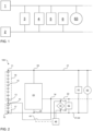
- Figure 2 schematically illustrates a circuit diagram of an electric vehicle with power supply system 100 according to a first embodiment of the present invention.
- the power supply system 100 comprises a plurality of stacked battery cells 10 forming a high voltage battery stack that is interconnected between a first stack node 11 and a second stack node 12.
- the power supply system 100 further comprises an intermediate node 13 and the stacked battery cells 10 are divided in a first cell sub-stack 16 between the first stack node 11 and the intermediate node 13 and a second cell sub-stack between the intermediate node 13 and the second stack node 12.
- Each of the first and second battery sub-stack 16,17 comprises a plurality of battery cells 10 connected in series.
- the first cell sub-stack 16 comprises nine battery cells 10, each with a capacity of about 4V
- the second cell sub-stack 17 comprises four battery cells 10, each with a capacity of about 4 V.
- the stacked battery cells 10 as a whole provide a voltage of about 48V that applies between the first and second stack node 11, 12 and the second sub-stack 17 provides a voltage of about 12V that applies between the intermediate node 13 and the second stack node 12.
- the first stack node 11 is on the added potential of the battery cells 10 connected in series between the first stack node 11 and second stack node 12, while the second terminal 12 is on ground potential.
- the first stack node 11 is electrically connected with a first electric line shown as upper limitation of the power supply system 100 and the second stack node 12 is electrically connected with a second electric line shown as lower limitation of the power supply system 100.
- These upper and lower lines form a high voltage board net 21 that spans between the first and second stack nodes 11, 12.
- a starter generator 63 and a first load 61 e.g. a 48V high voltage electronic control unit ECU, are connected to the high voltage board net, i.e. interconnected between the first and second stack node 11, 12.
- the power supply system 100 further comprises a DC/DC converter 23 connected in parallel to the stacked battery cells 10 between the first stack node 11 and the second stack node 12. Particularly, a first input node 24 of the step-down converter 23 is connected to the first stack node 11 and a second input node 25 of the step-down converter 23 is connected to the second stack node 12.
- the step-down converter 23 thus receives the voltage provided by the stacked battery cells 10, i.e. approximately 48V, as an input voltage.
- the step-down converter 23 is configured to output a reduced voltage via a low voltage node 14.
- the power supply system 100 further comprises a low voltage board net 22 that spans between the second stack node 12 and the low voltage node 14.
- a low voltage battery 15 is part of the low voltage board net 22 and is interconnected between the second stack node 12 and the low voltage node 14.
- the low voltage battery 15 is a lead accumulator configured to output a second operation voltage of approximately 12 V for supplying the low voltage board net 22.
- a second load 62 e.g. a 12V high voltage electronic control unit ECU, is connected to the high voltage board net 21, i.e. interconnected between the second stack node 12 and the low voltage node 14.
- the electric lines forming the high voltage board net 21 and the low voltage board net 22 are electrical conductors, e.g. wires, or conducting elements on a circuit carrier, e.g. metallizations or conducting polymers on a PCB.
- the power supply system 100 further comprises a control unit 46 that is configured to detect the terminal voltage of the low voltage battery 15. Therefore, the control unit 46 is electrically connected to a first voltage measurement node 31 at a first terminal of the low voltage battery 15 and to a second voltage measurement node 32 at a second terminal of the low voltage battery 15. The control unit 46 thus receives the voltage of the low voltage battery 15 as an input.
- the control unit 46 is further configured to control the conductivity of a first switching element 41 that is interconnected between the intermediate node 13 and the low voltage node 14.
- the control unit 46 is configured to set the conductivity of the first switching element 41 based on the detected terminal voltage of the low voltage battery 15. Particularly, if the terminal voltage of the low voltage battery 15 drops below a first predetermined voltage threshold, the control unit 46 sets the first switching element 41 conductive.
- the low voltage battery 15 may fail to supply the second load 62 that might be a security relevant load.
- the step-down converter 23 could principally supply the low voltage board net 22, relying solely on the converter 23 would require strict safety measures to be fulfilled by the converter 23.
- the low voltage board net 22 is supplied by the second sub-stack 17, i.e. with a fourth operation voltage of approximately 12V.
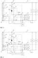
- FIG 3 schematically illustrates a circuit diagram of a power supply system 100 according to a second embodiment of the present invention. A description thereof is omitted where it equals the power supply system as illustrated in Figure 2 .
- the step-down converter 23 is specified to be a buck converter 23 that is connected in parallel with the plurality of battery cells 10 between the first stack node 11 and the second stack node 12.
- a first input node 24 of the buck converter 23 is electrically connected with the first stack node 11 and a second input node 25 of the buck converter 23 is electrically connected with the second stack node 12.
- the buck converter 23 comprises a second switching element 42 and an inductance 26 as energy storage element electrically connected in series between the first input node 24 and an output 31 of the buck converter 23, particularly between the second input node 24 and the low voltage node 14.
- the buck converter 23 further comprises a third switching element 43 interconnected between the second input node 25 and a first converter node 27, wherein the first converter node 27 is interconnected between the second switching element 42 and the energy storage inductance 26.
- a rectifying element e.g. a diode could be used instead of the third switching element 43.
- the first to third switching elements 41, 42, 43 are controlled by the control unit 46 as indicated by the dashed-dotted lines shown in Figures 2 and 3 .
- a rectifying element 28 in form of a diode 28 is interconnected between the low voltage node 14 and the energy storage element 26 in order to suppress a current towards the energy storage element 26, while the low voltage board net 22 is supplied by second sub-stack 17.
- the low voltage board net 22 is supplied via the low voltage battery 15 and the step-down converter 23.
- the output voltage of the buck converter 23 of Figure 3 is controlled by setting the duty cycles of the second and third switching elements 42, 43 via the control unit 46.
- the first switching element 41 is set conductive by the control unit 46 and the low voltage board net 22 is supplied by the second sub-stack 17.
- FIG 4 schematically illustrates a circuit diagram of a power supply system 100 according to a third embodiment of the present invention. A description thereof is omitted where it equals the power supply system 100 as illustrated in Figures 2 or 3 .
- a second converter node 30 of the step-down converter 23 is electrically connected to the intermediate node 13 via a fourth switching element 44 and a diode 33 as a second rectifying element 29.
- a fifth switching element 45 is interconnected between the first rectifying diode 28, 29 and the second converter node 30.
- the fourth and fifth switching elements 44, 45 are also controlled by the control unit 46.
- the power supply system 100 of Figure 4 thus allows for a third operation mode, wherein the step-down converter 23 is used for balancing the first and second sub-stacks 16, 17 and for charging the low voltage battery 15.
- the fourth switching element 44 is set conductive and the fifth switching element 45 is set non-conductive.
- the output voltage of the converter 23 at the second converter node 30 is set via the duty cycle of the second and third switching elements 42, 43.
- the fifth switching element 45 is set conductive and the fourth switching element 44 is set non-conductive.
- charging and balancing are performed in parallel by setting fourth and fifth switching elements 44, 45 conductive.
- first switching element 41 may be non-conductive.
- FIG. 5 schematically illustrates a circuit diagram of a power supply system 100 according to a fourth embodiment of the present invention. A description thereof is omitted where it equals the power supply system 100 as illustrated in Figures 2 to 4 .
- the second to fifth switching elements 42 to 45 are specified to be transistor switches. Particularly, the second and third switching element 42, 43 are realized by a pair of complementary bipolar transistors, i.e. a NPN bipolar transistor and a PNP bipolar transistor. Further, the fourth and fifth switching elements 44, 45 are realized by a pair of complementary bipolar transistors, i.e. a PNP bipolar transistor and a NPN bipolar transistor.
- the conductivity states of the second to fifth switching elements 42 to 45 can be advantageously controlled with only two control signals output by the control unit 46.
- the first and second voltage measurement nodes 31, 32 are disposed in the low voltage board net 22 instead of next to the terminals of the low voltage battery 15.
- Figure 6 schematically illustrates a circuit diagram of a power supply system 100 according to an illustrative example not part of the invention. A description thereof is omitted where it equals the power supply system 100 as illustrated in Figures 2 to 5 .
- the first rectifying diode 28, 29 is interconnected between the low voltage node 14 and the second converter node 30.
- the low voltage battery 15 is interconnected between the first rectifying diode 28, 29 and the second converter node 30.
- the power supply system of Figure 6 allows for a fourth operation mode, wherein charging of the low-voltage battery 15 via the step-down converter 23 can occur, while the low voltage board 22 net is operated by the second sub-stack 17 via the conductive first switching element 41.
- the low voltage board 22 net is operable via the second sub-stack 17 if the low voltage battery 15 is initially discharged, e.g. at a cold start, while the low voltage battery 15 is parallely charged for later use.
- the electronic or electric devices and/or any other relevant devices or components according to embodiments of the present invention described herein may be implemented utilizing any suitable hardware, firmware (e.g. an application-specific integrated circuit), software, or a combination of software, firmware, and hardware.
- the various components of these devices may be formed on one integrated circuit (IC) chip or on separate IC chips.
- the various components of these devices may be implemented on a flexible printed circuit film, a tape carrier package (TCP), a printed circuit board (PCB), or formed on one substrate.
- the electrical connections or interconnections described herein may be realized by wires or conducting elements, e.g. on a PCB or another kind of circuit carrier.
- the conducting elements may comprise metallization, e.g. surface metallizations and/or pins, and/or may comprise conductive polymers or ceramics. Further electrical energy might be transmitted via wireless connections, e.g. using electromagnetic radiation and/or light.
- the various components of these devices may be a process or thread, running on one or more processors, in one or more computing devices, executing computer program instructions and interacting with other system components for performing the various functionalities described herein.
- the computer program instructions are stored in a memory which may be implemented in a computing device using a standard memory device, such as, for example, a random access memory (RAM).
- the computer program instructions may also be stored in other non-transitory computer readable media such as, for example, a CD-ROM, flash drive, or the like.
Landscapes
- Engineering & Computer Science (AREA)
- Power Engineering (AREA)
- Transportation (AREA)
- Mechanical Engineering (AREA)
- Life Sciences & Earth Sciences (AREA)
- Sustainable Development (AREA)
- Sustainable Energy (AREA)
- Charge And Discharge Circuits For Batteries Or The Like (AREA)
Claims (14)
- Stromversorgungssystem (100) für ein Elektrofahrzeug, das Folgendes umfassteine Vielzahl von gestapelten Batteriezellen (10), die zwischen einem ersten Stapelknoten (11) und einem zweiten Stapelknoten (12) miteinander verbunden und so konfiguriert sind, dass sie eine erste Betriebsspannung zur Versorgung eines Hochspannungs-Bordnetzes (21) des Elektrofahrzeugs bereitstellen;ein Niederspannungs-Bordnetz (22) des Elektrofahrzeugs, das eine Niederspannungsbatterie (15) umfasst, die zwischen den zweiten Stapelknoten (12) und einen Niederspannungsknoten (14) geschaltet und so konfiguriert ist, dass sie eine zweite Betriebsspannung zur Versorgung des Niederspannungs-Bordnetzes (22) des Elektrofahrzeugs ausgibt;einen Abwärtswandler (23), der zwischen dem ersten Stapelknoten (11) und dem zweiten Stapelknoten (12) angeschlossen ist und so konfiguriert ist, dass er eine dritte Betriebsspannung an den Niederspannungsknoten (14) ausgibt; undeinen Zwischenknoten (13), der die Vielzahl von gestapelten Batteriezellen (10) in eine erste Teilmenge (16) von Batteriezellen (10) und eine zweite Teilmenge (17) von Batteriezellen (10) unterteilt und über ein erstes Schaltelement (41) mit dem Niederspannungsknoten (14) verbunden ist; undeine Steuereinheit (46), die so konfiguriert ist, dass sie die Klemmenspannung der Niederspannungsbatterie (15) erfasst und das erste Schaltelement (41) in Abhängigkeit von der erfassten Klemmenspannung entweder leitend oder nichtleitend einstellt, wobei die Steuereinheit (46) so konfiguriert ist, dass sie das erste Schaltelement (41) leitend einstellt, wenn die erfasste Klemmenspannung unter einem ersten vorgegebenen Spannungsschwellenwert liegt, und das erste Schaltelement (41) nichtleitend einstellt, wenn die erfasste Klemmenspannung über einem zweiten vorgegebenen Spannungsschwellenwert liegt,wobei die Niederspannungsbatterie (15) von der zweiten Untergruppe von Batteriezellen (17) über den Zwischenknoten (13) und den Niederspannungsknoten (14) versorgt wird, wenn das erste Schaltelement (41) leitend eingestellt ist, und von dem Abwärtswandler (23) über den Niederspannungsknoten (14), wenn das erste Schaltelement (41) nichtleitend eingestellt ist.
- Stromversorgungssystem (100) nach Anspruch 1, wobei die dritte Betriebsspannung kleiner oder gleich der zweiten Betriebsspannung ist und/oder die zweite Untergruppe (17) von Batteriezellen (10) eine vierte Betriebsspannung liefert, die zwischen der zweiten Betriebsspannung und der dritten Betriebsspannung liegt.
- Stromversorgungssystem (100) nach Anspruch 1, wobei die erste vorbestimmte Spannungsschwelle niedriger ist als mindestens eine der zweiten bis vierten Betriebsspannung.
- Stromversorgungssystem (100) nach einem der vorhergehenden Ansprüche,wobei der Abwärtswandler (23) einen ersten Eingangsknoten (24) umfasst, der mit dem ersten Stapelknoten (11) verbunden ist, und einen zweiten Eingangsknoten (25), der mit dem zweiten Stapelknoten (12) verbunden ist,wobei ein zweites Schaltelement (42) und ein Energiespeicherelement (26) zwischen dem ersten Eingangsknoten (24) und dem Niederspannungsknoten (14) angeschlossen sind,wobei ein drittes Schaltelement (43) zwischen den zweiten Eingangsknoten (25) und einen ersten Wandlerknoten (27) geschaltet ist, der elektrisch zwischen dem zweiten Schaltelement (42) und dem Energiespeicherelement (26) liegt.
- Stromversorgungssystem (100) nach Anspruch 4, wobei das Energiespeicherelement (26) eine Induktivität oder eine Kapazität ist.
- Stromversorgungssystem (100) nach Anspruch 4 oder 5, das ferner ein Gleichrichterelement (28) umfasst, das zwischen den Niederspannungsknoten (14) und den Abwärtswandler (23) geschaltet und so konfiguriert ist, dass es einen Strom von dem Niederspannungsknoten (14) zu dem Abwärtswandler (23) unterdrückt.
- Stromversorgungssystem (100) nach Anspruch 6, wobei das Gleichrichterelement (28) eine Diode (29) ist.
- Stromversorgungssystem (100) nach einem der vorhergehenden Ansprüche, wobei der Abwärtswandler (23) ferner so konfiguriert ist, dass er die dritte Betriebsspannung an den Zwischenknoten (13) ausgibt, um Energie von der ersten Untergruppe (16) von Batteriezellen (10) an die zweite Untergruppe (17) von Batteriezellen (10) zu übertragen.
- Stromversorgungssystem (100) nach Anspruch 8, wobei der Abwärtswandler (23) einen zweiten Wandlerknoten (30), der elektrisch zwischen dem Niederspannungsknoten (14) und dem Energiespeicherelement (26) angeschlossen ist, ein viertes Schaltelement (44), das elektrisch zwischen dem zweiten Wandlerknoten (30) und dem Zwischenknoten (13) angeschlossen ist, und ein fünftes Schaltelement (45), das elektrisch zwischen dem zweiten Wandlerknoten (30) und dem Niederspannungsknoten (14) angeschlossen ist, umfasst.
- Stromversorgungssystem (100) nach Anspruch 9, wobei die Steuereinheit (46) ferner so konfiguriert ist, dass sie die Leitfähigkeit des vierten Schaltelements (44) und/oder des fünften Schaltelements (45) steuert und/oder wobei ein zweites Paar komplementärer Transistoren für das vierte und fünfte Schaltelement (44, 45) verwendet wird.
- Stromversorgungssystem nach Anspruch 10, wobei die Steuereinheit (46) ferner so konfiguriert ist, dass sie die Leitfähigkeit des zweiten Schaltelements (42) und/oder des dritten Schaltelements (43) steuert und/oder wobei ein erstes Paar komplementärer Transistoren für das zweite und dritte Schaltelement (42, 43) verwendet wird.
- Fahrzeug mit einem Stromversorgungssystem (100) nach einem der Ansprüche 1 bis 11, ferner mit mindestens einer ersten Last (61), die zwischen dem ersten Stapelknoten (11) und dem zweiten Stapelknoten (12) angeschlossen ist, und mindestens einer zweiten Last (62), die zwischen dem zweiten Stapelknoten (12) und dem Niederspannungsknoten (14) angeschlossen ist.
- Fahrzeug mit einem Stromversorgungssystem (100) nach einem der Ansprüche 1 bis 11, das ferner einen Startergenerator (63) umfasst, der zwischen dem ersten Stapelknoten (11) und dem zweiten Stapelknoten (12) geschaltet ist.
- Fahrzeug nach Anspruch 12 oder 13, wobei die erste Last (61) eine Betriebsspannung von etwa 48 V und die zweite Last (62) eine Betriebsspannung von etwa 12 V aufweist.
Priority Applications (5)
| Application Number | Priority Date | Filing Date | Title |
|---|---|---|---|
| HUE18193097A HUE062311T2 (hu) | 2018-09-07 | 2018-09-07 | Tápegység rendszer |
| EP18193097.5A EP3620321B1 (de) | 2018-09-07 | 2018-09-07 | Stromversorgungssystem |
| PL18193097.5T PL3620321T3 (pl) | 2018-09-07 | 2018-09-07 | System zasilania |
| KR1020190020035A KR102607450B1 (ko) | 2018-09-07 | 2019-02-20 | 전원 공급 시스템 |
| US16/541,037 US11084397B2 (en) | 2018-09-07 | 2019-08-14 | Power supply system for vehicle with multiple operating voltages |
Applications Claiming Priority (1)
| Application Number | Priority Date | Filing Date | Title |
|---|---|---|---|
| EP18193097.5A EP3620321B1 (de) | 2018-09-07 | 2018-09-07 | Stromversorgungssystem |
Publications (2)
| Publication Number | Publication Date |
|---|---|
| EP3620321A1 EP3620321A1 (de) | 2020-03-11 |
| EP3620321B1 true EP3620321B1 (de) | 2023-04-12 |
Family
ID=63528554
Family Applications (1)
| Application Number | Title | Priority Date | Filing Date |
|---|---|---|---|
| EP18193097.5A Active EP3620321B1 (de) | 2018-09-07 | 2018-09-07 | Stromversorgungssystem |
Country Status (4)
| Country | Link |
|---|---|
| EP (1) | EP3620321B1 (de) |
| KR (1) | KR102607450B1 (de) |
| HU (1) | HUE062311T2 (de) |
| PL (1) | PL3620321T3 (de) |
Families Citing this family (5)
| Publication number | Priority date | Publication date | Assignee | Title |
|---|---|---|---|---|
| CN111555614A (zh) * | 2020-04-14 | 2020-08-18 | 中南大学 | 汽车双电源系统的交错dc-dc变换器及其控制方法 |
| DE102020111941B3 (de) * | 2020-05-04 | 2021-08-19 | Audi Aktiengesellschaft | Bordnetz für ein Kraftfahrzeug sowie Verfahren zum Betreiben eines Bordnetzes |
| CN114559818B (zh) * | 2021-03-02 | 2024-05-14 | 长城汽车股份有限公司 | 高低压系统、基于高压获取低压的方法以及电动汽车 |
| DE102021123099A1 (de) * | 2021-09-07 | 2023-03-09 | Kiekert Aktiengesellschaft | Kraftfahrzeug und Verwendung einer Fahrbatterie |
| DE102022105353A1 (de) * | 2022-03-08 | 2023-09-14 | Kiekert Aktiengesellschaft | Kraftfahrzeug insbesondere Elektro- oder Hybrid-Kraftfahrzeug |
Family Cites Families (6)
| Publication number | Priority date | Publication date | Assignee | Title |
|---|---|---|---|---|
| US6323608B1 (en) * | 2000-08-31 | 2001-11-27 | Honda Giken Kogyo Kabushiki Kaisha | Dual voltage battery for a motor vehicle |
| EP1568114B1 (de) * | 2002-11-25 | 2013-01-16 | Tiax Llc | Zellausgleichssystem zum ausgleich des ladezustandes unter reihengeschalteten elektrischen energiespeichereinheiten |
| JP5865013B2 (ja) * | 2011-10-27 | 2016-02-17 | 三洋電機株式会社 | 車両用の電源装置及びこの電源装置を備える車両 |
| DE102012220549A1 (de) * | 2012-11-12 | 2014-05-15 | Siemens Aktiengesellschaft | Elektro-Transportmittel, zugehöriges Verfahren und zugehöriger Akkumulator |
| EP3293036B1 (de) * | 2016-09-07 | 2021-08-25 | iN2POWER NV | Energietransfer von eltern-batterie zu slave-batterie für verbundsysteme |
| EP3360719B1 (de) * | 2017-02-09 | 2020-09-09 | Samsung SDI Co., Ltd | Doppeltes stromversorgungssystem |
-
2018
- 2018-09-07 PL PL18193097.5T patent/PL3620321T3/pl unknown
- 2018-09-07 EP EP18193097.5A patent/EP3620321B1/de active Active
- 2018-09-07 HU HUE18193097A patent/HUE062311T2/hu unknown
-
2019
- 2019-02-20 KR KR1020190020035A patent/KR102607450B1/ko active IP Right Grant
Also Published As
| Publication number | Publication date |
|---|---|
| KR102607450B1 (ko) | 2023-11-27 |
| PL3620321T3 (pl) | 2023-07-17 |
| HUE062311T2 (hu) | 2023-10-28 |
| EP3620321A1 (de) | 2020-03-11 |
| KR20200029327A (ko) | 2020-03-18 |
Similar Documents
| Publication | Publication Date | Title |
|---|---|---|
| US11407311B2 (en) | Dual power supply system | |
| EP3576241B1 (de) | Batteriesystem | |
| EP3620321B1 (de) | Stromversorgungssystem | |
| EP3316440B1 (de) | Batteriesystem mit integriertem ausgleich und verfahren zum ausgleich eines batteriesystems | |
| US11247582B2 (en) | Control electronics for a battery system, method for power supplying control electronics for a battery system, battery system and vehicle | |
| US11063460B2 (en) | Battery system | |
| EP3722137A1 (de) | Steuerelektronik für ein batteriesystem, verfahren zur stromversorgung der steuerelektronik für ein batteriesystem, batteriesystem und fahrzeug | |
| US11084397B2 (en) | Power supply system for vehicle with multiple operating voltages | |
| US11329564B2 (en) | Control system for a battery system | |
| EP3751715B1 (de) | Steuerungssystem für ein batteriesystem | |
| EP3863141A1 (de) | Batteriesystem | |
| US11801753B2 (en) | Battery system and vehicle including the battery system | |
| US11420533B2 (en) | Battery system | |
| US20210249872A1 (en) | Battery system | |
| US11476690B2 (en) | Power supply system | |
| EP3337002B1 (de) | Batteriesystem und steuereinheit für ein batteriesystem | |
| EP3812205A1 (de) | Stromversorgungssystem | |
| EP3890154A1 (de) | Batteriesystem | |
| EP3708403B1 (de) | Festkörperschaltertreiberschaltung für ein batteriesystem | |
| US11444337B2 (en) | Solid state switch driver circuit for a battery system | |
| EP4108496A1 (de) | Bidirektionales stromversorgungssystem zur speisung eines batteriemanagementsystems eines elektrischen fahrzeugs | |
| US20230170538A1 (en) | Battery system and method for operating the same | |
| EP4186746A1 (de) | Batteriesystem und verfahren zum betrieb davon | |
| US20210300207A1 (en) | Electric-vehicle battery system including a real time clock |
Legal Events
| Date | Code | Title | Description |
|---|---|---|---|
| PUAI | Public reference made under article 153(3) epc to a published international application that has entered the european phase |
Free format text: ORIGINAL CODE: 0009012 |
|
| STAA | Information on the status of an ep patent application or granted ep patent |
Free format text: STATUS: REQUEST FOR EXAMINATION WAS MADE |
|
| 17P | Request for examination filed |
Effective date: 20191213 |
|
| AK | Designated contracting states |
Kind code of ref document: A1 Designated state(s): AL AT BE BG CH CY CZ DE DK EE ES FI FR GB GR HR HU IE IS IT LI LT LU LV MC MK MT NL NO PL PT RO RS SE SI SK SM TR |
|
| AX | Request for extension of the european patent |
Extension state: BA ME |
|
| STAA | Information on the status of an ep patent application or granted ep patent |
Free format text: STATUS: EXAMINATION IS IN PROGRESS |
|
| 17Q | First examination report despatched |
Effective date: 20210623 |
|
| STAA | Information on the status of an ep patent application or granted ep patent |
Free format text: STATUS: EXAMINATION IS IN PROGRESS |
|
| GRAP | Despatch of communication of intention to grant a patent |
Free format text: ORIGINAL CODE: EPIDOSNIGR1 |
|
| STAA | Information on the status of an ep patent application or granted ep patent |
Free format text: STATUS: GRANT OF PATENT IS INTENDED |
|
| INTG | Intention to grant announced |
Effective date: 20221026 |
|
| GRAS | Grant fee paid |
Free format text: ORIGINAL CODE: EPIDOSNIGR3 |
|
| GRAA | (expected) grant |
Free format text: ORIGINAL CODE: 0009210 |
|
| STAA | Information on the status of an ep patent application or granted ep patent |
Free format text: STATUS: THE PATENT HAS BEEN GRANTED |
|
| AK | Designated contracting states |
Kind code of ref document: B1 Designated state(s): AL AT BE BG CH CY CZ DE DK EE ES FI FR GB GR HR HU IE IS IT LI LT LU LV MC MK MT NL NO PL PT RO RS SE SI SK SM TR |
|
| REG | Reference to a national code |
Ref country code: GB Ref legal event code: FG4D |
|
| REG | Reference to a national code |
Ref country code: CH Ref legal event code: EP |
|
| REG | Reference to a national code |
Ref country code: DE Ref legal event code: R096 Ref document number: 602018048257 Country of ref document: DE |
|
| REG | Reference to a national code |
Ref country code: IE Ref legal event code: FG4D |
|
| REG | Reference to a national code |
Ref country code: AT Ref legal event code: REF Ref document number: 1559582 Country of ref document: AT Kind code of ref document: T Effective date: 20230515 |
|
| REG | Reference to a national code |
Ref country code: SE Ref legal event code: TRGR |
|
| REG | Reference to a national code |
Ref country code: LT Ref legal event code: MG9D |
|
| REG | Reference to a national code |
Ref country code: NL Ref legal event code: MP Effective date: 20230412 |
|
| PG25 | Lapsed in a contracting state [announced via postgrant information from national office to epo] |
Ref country code: NL Free format text: LAPSE BECAUSE OF FAILURE TO SUBMIT A TRANSLATION OF THE DESCRIPTION OR TO PAY THE FEE WITHIN THE PRESCRIBED TIME-LIMIT Effective date: 20230412 |
|
| REG | Reference to a national code |
Ref country code: HU Ref legal event code: AG4A Ref document number: E062311 Country of ref document: HU |
|
| PG25 | Lapsed in a contracting state [announced via postgrant information from national office to epo] |
Ref country code: PT Free format text: LAPSE BECAUSE OF FAILURE TO SUBMIT A TRANSLATION OF THE DESCRIPTION OR TO PAY THE FEE WITHIN THE PRESCRIBED TIME-LIMIT Effective date: 20230814 Ref country code: NO Free format text: LAPSE BECAUSE OF FAILURE TO SUBMIT A TRANSLATION OF THE DESCRIPTION OR TO PAY THE FEE WITHIN THE PRESCRIBED TIME-LIMIT Effective date: 20230712 Ref country code: ES Free format text: LAPSE BECAUSE OF FAILURE TO SUBMIT A TRANSLATION OF THE DESCRIPTION OR TO PAY THE FEE WITHIN THE PRESCRIBED TIME-LIMIT Effective date: 20230412 |
|
| PGFP | Annual fee paid to national office [announced via postgrant information from national office to epo] |
Ref country code: GB Payment date: 20230824 Year of fee payment: 6 Ref country code: AT Payment date: 20230825 Year of fee payment: 6 |
|
| PG25 | Lapsed in a contracting state [announced via postgrant information from national office to epo] |
Ref country code: RS Free format text: LAPSE BECAUSE OF FAILURE TO SUBMIT A TRANSLATION OF THE DESCRIPTION OR TO PAY THE FEE WITHIN THE PRESCRIBED TIME-LIMIT Effective date: 20230412 Ref country code: LV Free format text: LAPSE BECAUSE OF FAILURE TO SUBMIT A TRANSLATION OF THE DESCRIPTION OR TO PAY THE FEE WITHIN THE PRESCRIBED TIME-LIMIT Effective date: 20230412 Ref country code: LT Free format text: LAPSE BECAUSE OF FAILURE TO SUBMIT A TRANSLATION OF THE DESCRIPTION OR TO PAY THE FEE WITHIN THE PRESCRIBED TIME-LIMIT Effective date: 20230412 Ref country code: IS Free format text: LAPSE BECAUSE OF FAILURE TO SUBMIT A TRANSLATION OF THE DESCRIPTION OR TO PAY THE FEE WITHIN THE PRESCRIBED TIME-LIMIT Effective date: 20230812 Ref country code: HR Free format text: LAPSE BECAUSE OF FAILURE TO SUBMIT A TRANSLATION OF THE DESCRIPTION OR TO PAY THE FEE WITHIN THE PRESCRIBED TIME-LIMIT Effective date: 20230412 Ref country code: GR Free format text: LAPSE BECAUSE OF FAILURE TO SUBMIT A TRANSLATION OF THE DESCRIPTION OR TO PAY THE FEE WITHIN THE PRESCRIBED TIME-LIMIT Effective date: 20230713 Ref country code: AL Free format text: LAPSE BECAUSE OF FAILURE TO SUBMIT A TRANSLATION OF THE DESCRIPTION OR TO PAY THE FEE WITHIN THE PRESCRIBED TIME-LIMIT Effective date: 20230412 |
|
| PGFP | Annual fee paid to national office [announced via postgrant information from national office to epo] |
Ref country code: SE Payment date: 20230830 Year of fee payment: 6 Ref country code: PL Payment date: 20230828 Year of fee payment: 6 Ref country code: HU Payment date: 20230901 Year of fee payment: 6 Ref country code: FR Payment date: 20230911 Year of fee payment: 6 Ref country code: DE Payment date: 20230830 Year of fee payment: 6 |
|
| PG25 | Lapsed in a contracting state [announced via postgrant information from national office to epo] |
Ref country code: FI Free format text: LAPSE BECAUSE OF FAILURE TO SUBMIT A TRANSLATION OF THE DESCRIPTION OR TO PAY THE FEE WITHIN THE PRESCRIBED TIME-LIMIT Effective date: 20230412 |
|
| REG | Reference to a national code |
Ref country code: DE Ref legal event code: R097 Ref document number: 602018048257 Country of ref document: DE |
|
| PG25 | Lapsed in a contracting state [announced via postgrant information from national office to epo] |
Ref country code: SK Free format text: LAPSE BECAUSE OF FAILURE TO SUBMIT A TRANSLATION OF THE DESCRIPTION OR TO PAY THE FEE WITHIN THE PRESCRIBED TIME-LIMIT Effective date: 20230412 |
|
| PG25 | Lapsed in a contracting state [announced via postgrant information from national office to epo] |
Ref country code: SM Free format text: LAPSE BECAUSE OF FAILURE TO SUBMIT A TRANSLATION OF THE DESCRIPTION OR TO PAY THE FEE WITHIN THE PRESCRIBED TIME-LIMIT Effective date: 20230412 Ref country code: SK Free format text: LAPSE BECAUSE OF FAILURE TO SUBMIT A TRANSLATION OF THE DESCRIPTION OR TO PAY THE FEE WITHIN THE PRESCRIBED TIME-LIMIT Effective date: 20230412 Ref country code: RO Free format text: LAPSE BECAUSE OF FAILURE TO SUBMIT A TRANSLATION OF THE DESCRIPTION OR TO PAY THE FEE WITHIN THE PRESCRIBED TIME-LIMIT Effective date: 20230412 Ref country code: EE Free format text: LAPSE BECAUSE OF FAILURE TO SUBMIT A TRANSLATION OF THE DESCRIPTION OR TO PAY THE FEE WITHIN THE PRESCRIBED TIME-LIMIT Effective date: 20230412 Ref country code: DK Free format text: LAPSE BECAUSE OF FAILURE TO SUBMIT A TRANSLATION OF THE DESCRIPTION OR TO PAY THE FEE WITHIN THE PRESCRIBED TIME-LIMIT Effective date: 20230412 Ref country code: CZ Free format text: LAPSE BECAUSE OF FAILURE TO SUBMIT A TRANSLATION OF THE DESCRIPTION OR TO PAY THE FEE WITHIN THE PRESCRIBED TIME-LIMIT Effective date: 20230412 |
|
| PLBE | No opposition filed within time limit |
Free format text: ORIGINAL CODE: 0009261 |
|
| STAA | Information on the status of an ep patent application or granted ep patent |
Free format text: STATUS: NO OPPOSITION FILED WITHIN TIME LIMIT |
|
| 26N | No opposition filed |
Effective date: 20240115 |
|
| REG | Reference to a national code |
Ref country code: CH Ref legal event code: PL |
|
| PG25 | Lapsed in a contracting state [announced via postgrant information from national office to epo] |
Ref country code: SI Free format text: LAPSE BECAUSE OF FAILURE TO SUBMIT A TRANSLATION OF THE DESCRIPTION OR TO PAY THE FEE WITHIN THE PRESCRIBED TIME-LIMIT Effective date: 20230412 |
|
| PG25 | Lapsed in a contracting state [announced via postgrant information from national office to epo] |
Ref country code: LU Free format text: LAPSE BECAUSE OF NON-PAYMENT OF DUE FEES Effective date: 20230907 |