EP3579006B1 - Validierung eines temperatursensors einer batteriezelle - Google Patents
Validierung eines temperatursensors einer batteriezelle Download PDFInfo
- Publication number
- EP3579006B1 EP3579006B1 EP18176431.7A EP18176431A EP3579006B1 EP 3579006 B1 EP3579006 B1 EP 3579006B1 EP 18176431 A EP18176431 A EP 18176431A EP 3579006 B1 EP3579006 B1 EP 3579006B1
- Authority
- EP
- European Patent Office
- Prior art keywords
- battery cell
- battery
- temperature
- soc
- internal resistance
- Prior art date
- Legal status (The legal status is an assumption and is not a legal conclusion. Google has not performed a legal analysis and makes no representation as to the accuracy of the status listed.)
- Active
Links
- 238000010200 validation analysis Methods 0.000 title description 4
- 238000000034 method Methods 0.000 claims description 48
- 238000005259 measurement Methods 0.000 claims description 37
- 238000009529 body temperature measurement Methods 0.000 claims description 20
- 230000004044 response Effects 0.000 claims description 18
- 238000005520 cutting process Methods 0.000 claims description 4
- 230000001052 transient effect Effects 0.000 claims description 4
- 230000006870 function Effects 0.000 description 22
- 229910001416 lithium ion Inorganic materials 0.000 description 6
- HBBGRARXTFLTSG-UHFFFAOYSA-N Lithium ion Chemical compound [Li+] HBBGRARXTFLTSG-UHFFFAOYSA-N 0.000 description 5
- 238000003745 diagnosis Methods 0.000 description 5
- 238000004891 communication Methods 0.000 description 3
- 238000004590 computer program Methods 0.000 description 3
- 230000001419 dependent effect Effects 0.000 description 3
- 238000011161 development Methods 0.000 description 3
- WHXSMMKQMYFTQS-UHFFFAOYSA-N Lithium Chemical compound [Li] WHXSMMKQMYFTQS-UHFFFAOYSA-N 0.000 description 2
- 229910005813 NiMH Inorganic materials 0.000 description 2
- 238000013459 approach Methods 0.000 description 2
- 230000006399 behavior Effects 0.000 description 2
- 238000012512 characterization method Methods 0.000 description 2
- 230000007423 decrease Effects 0.000 description 2
- 239000008151 electrolyte solution Substances 0.000 description 2
- 229910052744 lithium Inorganic materials 0.000 description 2
- 238000001465 metallisation Methods 0.000 description 2
- 230000008569 process Effects 0.000 description 2
- 230000009467 reduction Effects 0.000 description 2
- 238000012552 review Methods 0.000 description 2
- 238000004088 simulation Methods 0.000 description 2
- 239000000126 substance Substances 0.000 description 2
- 238000012360 testing method Methods 0.000 description 2
- 102100029095 Exportin-1 Human genes 0.000 description 1
- 229910018095 Ni-MH Inorganic materials 0.000 description 1
- 229910018477 Ni—MH Inorganic materials 0.000 description 1
- 101100485284 Saccharomyces cerevisiae (strain ATCC 204508 / S288c) CRM1 gene Proteins 0.000 description 1
- 101150094313 XPO1 gene Proteins 0.000 description 1
- 238000004458 analytical method Methods 0.000 description 1
- 230000001413 cellular effect Effects 0.000 description 1
- 239000000919 ceramic Substances 0.000 description 1
- 230000008859 change Effects 0.000 description 1
- 238000006243 chemical reaction Methods 0.000 description 1
- 229920001940 conductive polymer Polymers 0.000 description 1
- 238000010276 construction Methods 0.000 description 1
- 230000003247 decreasing effect Effects 0.000 description 1
- 230000006866 deterioration Effects 0.000 description 1
- 238000007599 discharging Methods 0.000 description 1
- 230000000694 effects Effects 0.000 description 1
- 238000012983 electrochemical energy storage Methods 0.000 description 1
- 238000003487 electrochemical reaction Methods 0.000 description 1
- 230000005670 electromagnetic radiation Effects 0.000 description 1
- 108700002148 exportin 1 Proteins 0.000 description 1
- 238000001914 filtration Methods 0.000 description 1
- 230000014509 gene expression Effects 0.000 description 1
- 238000001566 impedance spectroscopy Methods 0.000 description 1
- 238000009434 installation Methods 0.000 description 1
- 230000010354 integration Effects 0.000 description 1
- 230000002427 irreversible effect Effects 0.000 description 1
- 238000004519 manufacturing process Methods 0.000 description 1
- 238000000691 measurement method Methods 0.000 description 1
- 229910052987 metal hydride Inorganic materials 0.000 description 1
- 229920000642 polymer Polymers 0.000 description 1
- 238000012545 processing Methods 0.000 description 1
- 239000000523 sample Substances 0.000 description 1
- 230000003068 static effect Effects 0.000 description 1
- 238000003860 storage Methods 0.000 description 1
- 239000000758 substrate Substances 0.000 description 1
- 238000012800 visualization Methods 0.000 description 1
Images

Classifications
-
- G—PHYSICS
- G01—MEASURING; TESTING
- G01R—MEASURING ELECTRIC VARIABLES; MEASURING MAGNETIC VARIABLES
- G01R31/00—Arrangements for testing electric properties; Arrangements for locating electric faults; Arrangements for electrical testing characterised by what is being tested not provided for elsewhere
- G01R31/36—Arrangements for testing, measuring or monitoring the electrical condition of accumulators or electric batteries, e.g. capacity or state of charge [SoC]
- G01R31/385—Arrangements for measuring battery or accumulator variables
- G01R31/387—Determining ampere-hour charge capacity or SoC
-
- G—PHYSICS
- G01—MEASURING; TESTING
- G01R—MEASURING ELECTRIC VARIABLES; MEASURING MAGNETIC VARIABLES
- G01R31/00—Arrangements for testing electric properties; Arrangements for locating electric faults; Arrangements for electrical testing characterised by what is being tested not provided for elsewhere
- G01R31/28—Testing of electronic circuits, e.g. by signal tracer
- G01R31/282—Testing of electronic circuits specially adapted for particular applications not provided for elsewhere
- G01R31/2829—Testing of circuits in sensor or actuator systems
-
- G—PHYSICS
- G01—MEASURING; TESTING
- G01R—MEASURING ELECTRIC VARIABLES; MEASURING MAGNETIC VARIABLES
- G01R31/00—Arrangements for testing electric properties; Arrangements for locating electric faults; Arrangements for electrical testing characterised by what is being tested not provided for elsewhere
- G01R31/36—Arrangements for testing, measuring or monitoring the electrical condition of accumulators or electric batteries, e.g. capacity or state of charge [SoC]
- G01R31/367—Software therefor, e.g. for battery testing using modelling or look-up tables
-
- G—PHYSICS
- G01—MEASURING; TESTING
- G01R—MEASURING ELECTRIC VARIABLES; MEASURING MAGNETIC VARIABLES
- G01R31/00—Arrangements for testing electric properties; Arrangements for locating electric faults; Arrangements for electrical testing characterised by what is being tested not provided for elsewhere
- G01R31/36—Arrangements for testing, measuring or monitoring the electrical condition of accumulators or electric batteries, e.g. capacity or state of charge [SoC]
- G01R31/374—Arrangements for testing, measuring or monitoring the electrical condition of accumulators or electric batteries, e.g. capacity or state of charge [SoC] with means for correcting the measurement for temperature or ageing
-
- G—PHYSICS
- G01—MEASURING; TESTING
- G01R—MEASURING ELECTRIC VARIABLES; MEASURING MAGNETIC VARIABLES
- G01R31/00—Arrangements for testing electric properties; Arrangements for locating electric faults; Arrangements for electrical testing characterised by what is being tested not provided for elsewhere
- G01R31/36—Arrangements for testing, measuring or monitoring the electrical condition of accumulators or electric batteries, e.g. capacity or state of charge [SoC]
- G01R31/382—Arrangements for monitoring battery or accumulator variables, e.g. SoC
- G01R31/3842—Arrangements for monitoring battery or accumulator variables, e.g. SoC combining voltage and current measurements
-
- G—PHYSICS
- G01—MEASURING; TESTING
- G01R—MEASURING ELECTRIC VARIABLES; MEASURING MAGNETIC VARIABLES
- G01R31/00—Arrangements for testing electric properties; Arrangements for locating electric faults; Arrangements for electrical testing characterised by what is being tested not provided for elsewhere
- G01R31/36—Arrangements for testing, measuring or monitoring the electrical condition of accumulators or electric batteries, e.g. capacity or state of charge [SoC]
- G01R31/389—Measuring internal impedance, internal conductance or related variables
-
- G—PHYSICS
- G01—MEASURING; TESTING
- G01R—MEASURING ELECTRIC VARIABLES; MEASURING MAGNETIC VARIABLES
- G01R31/00—Arrangements for testing electric properties; Arrangements for locating electric faults; Arrangements for electrical testing characterised by what is being tested not provided for elsewhere
- G01R31/36—Arrangements for testing, measuring or monitoring the electrical condition of accumulators or electric batteries, e.g. capacity or state of charge [SoC]
- G01R31/392—Determining battery ageing or deterioration, e.g. state of health
-
- G—PHYSICS
- G01—MEASURING; TESTING
- G01R—MEASURING ELECTRIC VARIABLES; MEASURING MAGNETIC VARIABLES
- G01R31/00—Arrangements for testing electric properties; Arrangements for locating electric faults; Arrangements for electrical testing characterised by what is being tested not provided for elsewhere
- G01R31/36—Arrangements for testing, measuring or monitoring the electrical condition of accumulators or electric batteries, e.g. capacity or state of charge [SoC]
- G01R31/396—Acquisition or processing of data for testing or for monitoring individual cells or groups of cells within a battery
-
- H—ELECTRICITY
- H01—ELECTRIC ELEMENTS
- H01M—PROCESSES OR MEANS, e.g. BATTERIES, FOR THE DIRECT CONVERSION OF CHEMICAL ENERGY INTO ELECTRICAL ENERGY
- H01M10/00—Secondary cells; Manufacture thereof
- H01M10/42—Methods or arrangements for servicing or maintenance of secondary cells or secondary half-cells
- H01M10/425—Structural combination with electronic components, e.g. electronic circuits integrated to the outside of the casing
-
- H—ELECTRICITY
- H01—ELECTRIC ELEMENTS
- H01M—PROCESSES OR MEANS, e.g. BATTERIES, FOR THE DIRECT CONVERSION OF CHEMICAL ENERGY INTO ELECTRICAL ENERGY
- H01M10/00—Secondary cells; Manufacture thereof
- H01M10/42—Methods or arrangements for servicing or maintenance of secondary cells or secondary half-cells
- H01M10/48—Accumulators combined with arrangements for measuring, testing or indicating the condition of cells, e.g. the level or density of the electrolyte
- H01M10/482—Accumulators combined with arrangements for measuring, testing or indicating the condition of cells, e.g. the level or density of the electrolyte for several batteries or cells simultaneously or sequentially
-
- H—ELECTRICITY
- H01—ELECTRIC ELEMENTS
- H01M—PROCESSES OR MEANS, e.g. BATTERIES, FOR THE DIRECT CONVERSION OF CHEMICAL ENERGY INTO ELECTRICAL ENERGY
- H01M10/00—Secondary cells; Manufacture thereof
- H01M10/42—Methods or arrangements for servicing or maintenance of secondary cells or secondary half-cells
- H01M10/48—Accumulators combined with arrangements for measuring, testing or indicating the condition of cells, e.g. the level or density of the electrolyte
- H01M10/486—Accumulators combined with arrangements for measuring, testing or indicating the condition of cells, e.g. the level or density of the electrolyte for measuring temperature
-
- H—ELECTRICITY
- H01—ELECTRIC ELEMENTS
- H01M—PROCESSES OR MEANS, e.g. BATTERIES, FOR THE DIRECT CONVERSION OF CHEMICAL ENERGY INTO ELECTRICAL ENERGY
- H01M10/00—Secondary cells; Manufacture thereof
- H01M10/42—Methods or arrangements for servicing or maintenance of secondary cells or secondary half-cells
- H01M10/425—Structural combination with electronic components, e.g. electronic circuits integrated to the outside of the casing
- H01M2010/4271—Battery management systems including electronic circuits, e.g. control of current or voltage to keep battery in healthy state, cell balancing
-
- Y—GENERAL TAGGING OF NEW TECHNOLOGICAL DEVELOPMENTS; GENERAL TAGGING OF CROSS-SECTIONAL TECHNOLOGIES SPANNING OVER SEVERAL SECTIONS OF THE IPC; TECHNICAL SUBJECTS COVERED BY FORMER USPC CROSS-REFERENCE ART COLLECTIONS [XRACs] AND DIGESTS
- Y02—TECHNOLOGIES OR APPLICATIONS FOR MITIGATION OR ADAPTATION AGAINST CLIMATE CHANGE
- Y02E—REDUCTION OF GREENHOUSE GAS [GHG] EMISSIONS, RELATED TO ENERGY GENERATION, TRANSMISSION OR DISTRIBUTION
- Y02E60/00—Enabling technologies; Technologies with a potential or indirect contribution to GHG emissions mitigation
- Y02E60/10—Energy storage using batteries
Definitions
- the present invention relates to a method for validating a temperature sensor integrated into a battery system, particularly for validating a temperature measurement of that temperature sensor.
- the present invention further relates to a battery system comprising at least one battery cell, a temperature sensor in thermal contact with the battery cell and a control unit that is configured for performing the validation method of the present invention.
- a rechargeable or secondary battery differs from a primary battery in that it can be repeatedly charged and discharged, while the latter provides only an irreversible conversion of chemical to electrical energy.
- Low-capacity rechargeable batteries are used as power supply for small electronic devices, such as cellular phones, notebook computers and camcorders, while high-capacity rechargeable batteries are used as the power supply for hybrid vehicles and the like.
- rechargeable batteries include an electrode assembly including a positive electrode, a negative electrode, and a separator interposed between the positive and negative electrodes, a case receiving the electrode assembly, and an electrode terminal electrically connected to the electrode assembly.
- An electrolyte solution is injected into the case in order to enable charging and discharging of the battery via an electrochemical reaction of the positive electrode, the negative electrode, and the electrolyte solution.
- the shape of the case e.g. cylindrical or rectangular, depends on the battery's intended purpose.
- Rechargeable batteries may be used as a battery module formed of a plurality of unit battery cells coupled in series and/or in parallel so as to provide a high energy density, e.g. for motor driving of a hybrid vehicle. That is, the battery module is formed by interconnecting the electrode terminals of the plurality of unit battery cells depending on a required amount of power and in order to realize a high-power rechargeable battery, e.g. for an electric vehicle.
- BMS battery management system
- the BMS is usually coupled to the controller of one or more electrical consumers as well as to each of the battery modules of the battery system.
- a daisy chain setup may be used for controlling a plurality of battery modules by a single BMS.
- the BMS as master, is connected for communication in series to a plurality of battery modules, particularly to a plurality of cell supervision circuits, CSC, of the respective battery modules.
- the CSC may be arranged on a printed circuit board, PCB, on top of a respective battery module.
- a plurality of sensors is utilized for determining the information on the battery cells therein.
- the number of sensors that can be utilized is limited, particularly in smaller battery modules or systems.
- the impact or the risk of a faulty measurement due to a malfunctioning sensor increases as the number of a certain sensor species decreases.
- a minimum amount of each sensor species has thus to be installed even into small systems. Then a validation of the individual sensors can be achieved by cross comparison of their respective measurement results.
- US 2014/139149 A1 discloses a method for converting values of a standardized power output of a battery at 25°C/50% SOC to values of power output that are present at another temperature and at another SOC.
- XIONG RUI ET AL "Review on sensors fault diagnosis and fault-tolerant techniques for lithium ion batteries in electric vehicles", 2018 13TH IEEE CONFERENCE ON INDUSTRIAL ELECTRONICS AND APPLICATIONS (ICIEA), IEEE, 31 May 2018 (2018-05-31), pages 406-410, XP033366500, DOI: 10.1109/ICIEA.2018.8397751 discloses a comprehensive review of techniques for sensors fault diagnosis and tolerance for lithium ion batteries in EVs from the perspectives of model-based approaches.
- a method for validating a temperature sensor particularly for validating a measurement of a temperature sensor, as defined in claim 1 is provided.
- an internal resistance as well as a state of charge, SOC, of at least one battery cell which is in thermal contact with a temperature sensor to be validated, is determined.
- the internal resistance R I and the SOC are key performance indicators for battery cells that are commonly determined in many available battery systems and various methods for determining the internal resistance, R I , and the state of charge, SOC, of a battery cell are known to the person skilled in the art.
- At least one reference temperature is determined from a lookup table, LUT, or a functional relationship, which are connecting at least the internal resistance, the SOC, and the temperature of a reference battery cell, and preferably connect the internal resistance, the SOC, the temperature, and the current height of a reference battery cell.
- the LUT or functional relationship connects each pair of values for the internal resistance and the state of charge to exactly one value of a temperature of the reference battery cell.
- the LUT could also map a plurality of values for SOC and/or R I to the same temperature value of a reference battery cell, i.e. provide different classes of temperatures for the reference battery cell. Further preferred, values for the SOC and the R I are determined for a plurality of battery cells in thermal contact with the temperature sensor and a plurality of reference temperatures, one for each cell, is determined from the LUT or functional relationship. Particularly preferred, the reference battery cell is of the same type as the at least one battery cell in thermal contact with the temperature sensor to be validated.
- the at least one reference temperature is finally compared with a temperature measurement of the temperature sensor to be validated. Based on the result of this comparison, the temperature sensor or the temperature measurement of the temperature sensor can be validated.
- the method of the present invention thus advantageously allows validating even a single temperature sensor by utilizing the characteristic values of SOC and internal resistance, and preferably also the current height, that are already obtained in many battery systems. This is enabled by the inventive use of the LUT or functional relationship linking the values of the SOC and internal resistance of a battery cell to the temperature of a reference battery cell.
- a reference temperature for the battery cell is derived from the values of SOC and internal resistance.
- the LUT is determined in a test stand during development of the battery cells.
- the LUT is based on a plurality of reference measurements of an internal resistance of the reference cell that are obtained at a plurality of different temperatures of the reference battery cell and for a plurality of different SOC values of the reference battery cell.
- SOC and the internal resistance of the reference battery cell any method known to the person skilled in the art can be used. Exemplarily, the methods mentioned below can be used.
- the LUT is then stored as a data field on a suitable data structure, e.g. in the CSC/BMS of one or more battery modules/systems with battery cells corresponding to the reference battery cell.
- the functional relationship is based on an equivalent circuit model of the at least one battery cell.
- An example of such an equivalent circuit model is described in Huria T et al., High Fidelity Electrical Model with Thermal Dependence for Characterization and Simulation of High Power Lithium Battery Cells, 978-1-4673-1561-6, 2012 .
- a set of equations and/or a parametrized function, which are connecting the SOC, the internal resistance, and the temperature of the at least one battery cell are derived from such equivalent circuit model.
- the parameters of the parametrized function are fitted to the plurality of reference measurements as described above. Additionally, each of the aforementioned functions may further depend on one or more further characteristic values of a battery cell. Then, the respective function may also be fitted to a reference battery cell based on measurements of this one or more further characteristic values during development or testing.
- an LUT i.e. an extensive data field
- a parametrized function with fitted parameters is stored and utilized for determining the temperature of the at least one battery cell based on a determined SOC and internal resistance with minimal computational effort.
- an equivalent circuit model of the reference battery cell is combined with a plurality of reference measurements of an internal resistance of the reference battery cell, which are obtained at a plurality of different temperatures and for a plurality of different SOC values of the reference battery cell.
- the parameters of the parametrized function are determined (fitted) by fitting the parametrized function to the values obtained by such a plurality of reference measurements.
- the LUT is determined based on the parametrized function with fitted parameters.
- the number of required reference measurements can thus be minimized. Special care has to be taken, that all specific characteristics of the used electrochemical energy storage device are represented in the LUT.
- a continuous LUT or a functional relationship can be determined connecting a reference temperature to any combination of SOC and internal resistance of a battery cell.
- the functional relationship refers to a fitted parametrized function connecting a reference temperature to any combination of SOC and internal resistance of a battery cell.
- a difference between the at least one reference temperature and the temperature measurement of the temperature sensor is determined.
- differences between each of a plurality of reference temperatures, each obtained for one of a plurality of battery cells in thermal contact with the temperature sensor, and a temperature measurement of the temperature sensor are determined.
- multiple temperature measurements are utilized for comparison with one or more reference temperatures, in the form of individual values or of mean values.
- the thus obtained one or more (temperature) differences are compared to a preconfigured threshold and the at least one battery cell is validated based on whether the obtained one or more (temperature) differences exceeds the preconfigured threshold.
- the temperature difference(s) is/are to be smaller than the preconfigured threshold, the temperature sensor is determined to function correctly and if the temperature difference(s) exceed(s) the preconfigured threshold the temperature sensor is determined to function incorrectly.
- a control signal is outputted if the temperature difference exceeds the preconfigured threshold.
- the control signal is outputted from a control unit, e.g. of a battery system, performing the method of the invention.
- control signal is further processed in the control unit of a battery system comprising the battery cell or of a load apparatus connected to the battery system.
- a notification to a user is outputted, e.g. via a graphical user interface, GUI, or other human machine interface, HMI, of e.g. the battery system or load apparatus.
- a flag is set in a data structure marking the validated temperature sensor to be functional or non-functional. No further measures as described before may be initiated if the flag is set only sporadically.
- the steps of determining the internal resistance, of determining the state of charge of the at least one battery cell and the temperature measurement of the temperature sensor are all performed during a preconfigured period of time.
- the preconfigured period of time is less than 30 s, less than 15 s, less than 10 s, less than 5 s, or less than 1 s.
- the comparability of reference temperature(s) and temperature measurement(s) is further increased by improving the thermal contact between the temperature sensor and the at least one battery cell.
- Various methods for increasing thermal contact e.g. by ensuring sufficient mechanical contact with a spring loaded measuring head or using heat-conducting paste, are known to the person skilled in the art.
- reference temperatures obtained from the LUT or functional relationship using the SOC and the internal resistance of a specific battery cell are used only for validation of temperature sensor(s) that is (are) intended for performing temperature measurements of that specific battery cell.
- the internal resistance of a battery cell refers to the resistance of a virtual impedance which is considered to be connected in series with an ideal voltage source in an equivalent circuit model of the battery cell.
- the internal resistance of the at least one battery cell can be determined using any method known to the skilled person.
- the internal resistance of at least one battery cell is determined by measuring a voltage drop of the battery cell during a charging or discharge pulse of the battery cell. While the battery cell delivers a current to a load, i.e. during a discharge pulse, or while a current is provided to the battery cell, i.e. during a charging pulse, a measured voltage output of the battery cell is less than the open-circuit voltage, OCV, of the battery cell.
- the internal resistance can be calculated using the known value of the drawn or provided current.
- a short discharge pulse or charge pulse ⁇ 30 s preferably ⁇ 20 s, further preferred ⁇ 10 s, particularly preferred ⁇ 5 s and also preferred ⁇ 1 s.
- the voltage drop of the battery cell is measured during a balancing current is drawn from or provided to the battery cell.
- balancing current is usually a well defined current.
- the voltage drop is measured with respect to an actual terminal voltage of the at least one battery cell and in response to a specific load current drawn from the at least one battery cell.
- an actual terminal voltage is determined by initially measuring the cell's open-circuit voltage at the beginning of the step of determining the internal resistance of the at least one battery cell.
- a well defined load current is drawn from the at least one battery cell or the drawn load current is measured using at least one current sensor, e.g. a shunt resistor with well-defined ohmic resistance.
- the voltage drop is determined as the step response of the battery's terminal voltage with respect to the initially measured open circuit voltage.
- the voltage drop over a load with well defined ohmic resistance is used for determining the internal resistance of a battery cell using the OCV of the cell.
- the internal resistance of at least one battery cell is determined by measuring a voltage transient in response to cutting a specific load from the at least one battery cell. Due to the discharge of the battery cell in response to the load current, the battery cell's voltage will return to another OCV than the initially measured OCV.
- the voltage transient is thus determined as the step response of the voltage after cutting the load.
- the step response refers to an essential vertical portion of the graph.
- the voltage transient is the absolute value of the voltage difference between (i) the terminal voltage just before the load was cut and (ii) the terminal voltage at which the rate of change of the voltage can again be resolved.
- the state of charge refers to the actual charging state of a battery cell relative to the battery's maximal capacity.
- Various methods for determining a battery cell's state of charge are known to the person skilled in the art and, in principal, each of these methods can be employed in the method of the invention.
- the measurement method may depend on the actual battery type, e.g. whether the cell is a lithium ion, Li-ion, battery cell or a nickel-metal hydride, NiMH, battery cell.
- the SOC of the at least one battery cell is preferably determined based on at least one of: coulomb counting (current integration method), a voltage based method, impedance spectroscopy, chemical methods (e.g. hydrometer based methods), pressure-based methods (only for NiMH batteries), Kalman filtering, or by a combination of the aforementioned methods.
- the SOC of the at least one battery cell is determined based on measuring an actual terminal voltage of the at least one battery cell.
- the deterioration of the terminal voltage in dependence of the state of charge is known for the at least one battery cell.
- the SOC can be derived via a SOC-LUT or a SOC functional relationship that connect an actual terminal voltage to a SOC value.
- a SOC-LUT is utilized for determining a reference SOC based on a measurement of the actual terminal voltage.
- the SOC-LUT or SOC functional relationship is preferably obtained from a plurality of reference measurements of a reference battery cell of the same type as the at least one battery cell and/or an equivalent circuit model of the at least one battery cell.
- the terminal voltage is measured for a plurality of known SOCs, wherein the SOC of the reference cell may be determined by any of the methods mentioned above.
- the reference measurements may be combined with an equivalent circuit model of the at least one battery cell providing one or more equations or a parametrized function relating the SOC of the battery cell to its actual terminal voltage. Therein, the equations may be solved numerically and/or the parameters of the function may be fitted based on the reference measurements.
- a SOC-LUT or a parametrized function with fitted parameters is stored and utilized for determining SOC from the actual terminal voltage with low computational effort.
- the measurement of an actual terminal voltage is advantageously utilized for determining the SOC and the internal resistance of the cell.
- a battery system as described in claim 10 that comprises at least one battery cell and at least one temperature sensor which is in thermal contact with the at least one battery cell.
- the battery system further comprises at least one voltage sensor for measuring a terminal voltage of the at least one battery cell and a control unit that is configured for performing the method of the present invention as described in claims 1-9.
- the temperature sensor comprises a thermistor, e.g. a negative temperature coefficient, NTC, which is in thermal contact with the battery cell of the battery module.
- NTC negative temperature coefficient
- the voltage sensor may be a Hall probe, another suitable voltage sensor or measurement circuit.
- control unit is configured for receiving temperature measurements from the at least one temperature sensor and terminal voltage measurements of the at least one voltage sensor. Further preferred, the control unit is configured for determining the SOC and the internal resistance of the at least one battery cell utilizing the received voltage measurements. Therefore, the control unit preferably comprises a memory storing a SOC-LUT that is relating the SOC of a reference battery cell to its actual terminal voltage.
- control unit is preferably configured for drawing a well defined load current from the battery cell, for providing a well defined charging current to the battery cell or for drawing/providing a well defined balancing current from/to the battery cell, for measuring a voltage drop of the terminal voltage of the cell during the load current, charging current or balancing current is drawn or provided, and for calculating an internal resistance from the load, charging, or balancing current and the terminal voltage drop.
- the control unit also comprises a memory storing a LUT relating the SOC and the internal resistance of the at least one battery cell with the actual temperature of a reference battery cell and is further configured for determining a reference temperature for the at least one battery cell utilizing the SOC and internal resistance of the at least one battery cell and the LUT.
- a characteristic current (within some margin) is used for the resistance determination.
- the current height should be predefined, depending on the application area of the monitored battery.
- the battery system comprises at least one battery module with a plurality of aligned battery cells connected in series and/or in parallel between module terminals of the battery module.
- At least one temperature sensor is in thermal contact with at least one battery cell of the battery module.
- at least one voltage sensor is configured for measuring a terminal voltage of a battery cell of the battery module and at least one current sensor is configured for measuring a load current of this battery cell of the battery module.
- the control unit comprises at least one cell supervision circuit, CSC, that is connected to one of the at least one battery module.
- the CSC is disposed on a (flexible) PCB that is mechanically connected to the battery module, e.g. to a top surface or a side surface of the battery module.
- the CSC is preferably configured for receiving measurement values of the sensors, i.e. of the at least one temperature sensor, at least one voltage sensor, and at least one current sensor of that battery module that is connected to the CSC. At least some of the sensors or sensor components may be formed as a part of the CSC and/or disposed on the (flexible) PCB.
- control unit of the battery system also comprises a battery management system, BMS, which is connected to at least one CSC.
- the battery system comprises a plurality of battery modules, a plurality of CSCs connected thereto, and a BMS connected to the plurality of CSCs.
- the BMS may be connected to the plurality of CSCs in a daisy chain configuration or via a suitable communication bus, such as e.g. a CAN bus.
- the BMS may be further configured for communication with the CSCs as well as with electrical consumers located outside the battery system and connected to the battery system.
- the BMS is preferably configured for receiving voltage measurement, current measurement, and temperature measurement values from the at least one connected CSC. Based on these received measurement values, the BMS preferably determines SOC and internal resistance of at least one battery cell of the battery module connected to the at least one CSC from which at least the voltage and current values originate. Therefore, the BMS preferably comprises and utilizes a memory storing a SOC-LUT relating the SOC of a reference battery cell to its actual terminal voltage. Further preferred, the BMS is configured for calculating an internal resistance from the received current and voltage measurements. The BMS is also configured for determining at least one reference temperature based on the determined SOC and internal resistance of the at least one battery cell. Therefore the BMS preferably comprises a memory storing a LUT relating the determined SOC and internal resistance with the temperature of a reference battery cell.
- the BMS is finally configured for comparing the determined at least one reference temperature to the at least one received temperature value and for outputting a control signal based on whether or not a difference between the at least one measured temperature and the at least one determined reference temperature exceeds a preconfigured threshold.
- the measurement tasks and the computing tasks are distributed in the battery system.
- storage of the LUTs is only required within the BMS.
- the electronic or electric devices and/or any other relevant devices or components according to embodiments of the present invention described herein, except those described explicitly as hardware, may be implemented utilizing any suitable hardware, firmware (e.g. an application-specific integrated circuit), software, or a combination of software, firmware, and hardware.
- firmware e.g. an application-specific integrated circuit
- software e.g. an application-specific integrated circuit
- the various components of these devices may be formed on one integrated circuit (IC) chip or on separate IC chips.
- the various components of these devices may be implemented on a flexible printed circuit film, a tape carrier package (TCP), a printed circuit board (PCB), or formed on one substrate.
- the electrical connections or interconnections described herein may be realized by wires or conducting elements, e.g. on a PCB or another kind of circuit carrier.
- the conducting elements may comprise metallization, e.g. surface metallizations and/or pins, and/or may comprise conductive polymers or ceramics. Further electrical energy might be transmitted via wireless connections, e.g. using electromagnetic radiation and/or light.
- the various components of these devices may be a process or thread, running on one or more processors, in one or more computing devices, executing computer program instructions and interacting with other system components for performing the various functionalities described herein.
- the computer program instructions are stored in a memory which may be implemented in a computing device using a standard memory device, such as, for example, a random access memory (RAM).
- the computer program instructions may also be stored in other non-transitory computer readable media such as, for example, a CD-ROM, flash drive, or the like.
- first and second are used to describe various elements, these elements should not be limited by these terms. These terms are only used to distinguish one element from another element. For example, a first element may be named a second element and, similarly, a second element may be named a first element, without departing from the scope of the present invention.
- the term "and/or" includes any and all combinations of one or more of the associated listed items. Expressions such as “at least one of,” when preceding a list of elements, modify the entire list of elements and do not modify the individual elements of the list.
- the term “substantially,” “about,” and similar terms are used as terms of approximation and not as terms of degree, and are intended to account for the inherent deviations in measured or calculated values that would be recognized by those of ordinary skill in the art. Further, if the term “substantially” is used in combination with a feature that could be expressed using a numeric value, the term “substantially” denotes a range of +/- 5% of the value centered on the value.
- Figure 1 illustrates an equivalent circuit of a battery cell that can be used for deriving an LUT for the method of the present invention.
- the battery cell is modelled in first order as a series connection of an ideal voltage source providing the source voltage Us and an internal resistance R I .
- the equivalent circuit provides a terminal voltage U, between two external terminals of the circuit, e.g. to an external load. Therein, terminal voltage U, can be mapped to a real battery cell's terminal voltage and is smaller than the source voltage U S , at least once a load is connected to the external terminals of the equivalent circuit.
- a first RC element RC 1 comprises a first resistance R 1 connected in parallel with a first capacitance C 1 and a second RC element RC 2 comprises a second resistance R 2 connected in parallel with a second capacitance C 2 .
- the values of the second resistance R 2 and the second capacitance C 2 are smaller than the values of the first resistance R 1 and the first capacitance C 1 , respectively.
- the RC elements RC 1 and RC 2 thus allow for a series expansion of the battery cell's impedance and thus for a best fit of the equivalent circuit to even the non-linear performance characteristics of a real battery cell.
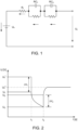
- Figure 2 illustrates a time series of the terminal voltage U, of the equivalent circuit of Figure 1 .
- the terminal voltage U, of the equivalent circuit is roughly equal to a first source voltage U S 1 (open circuit voltage) which corresponds to a first state of charge of the battery cell.
- U S 1 open circuit voltage
- an external load is connected to the external terminals of the circuit of Figure 1 .
- the external load draws a specific load I L current from the battery cell.
- the terminal voltage U t drops with a step response almost instantaneously before decreasing further at a smaller rate until the time point t 2 .
- the step response voltage drop ⁇ V 1 of the terminal voltage is due to the voltage drop over the internal resistance R I due to the load current I L .
- R I ⁇ V 1 / I L .
- the further non-linear decrease of the terminal voltage U, in between the time points t 1 and t 2 is best explained by the behavior of the RC elements RC 1 and RC 2 and can be thus considered to be independent of the internal resistance's magnitude to a large extent.
- the load is disconnected (cut) from the external terminals of the circuit of Figure 1 and hence the load current I L is suspended.
- the terminal voltage U t of the battery cell recovers towards the open cell voltage of the battery cell.
- the terminal voltage settles at a source voltage U S 2 which is smaller than the initial source voltage U S 1 .
- the step response of the voltage is due to the internal resistance R I , particularly due to the omitted voltage drop at the internal resistance after the ceasing of the load current I L .
- the further non-linear increase of the terminal voltage U, after time point t 2 is again due to the behavior of the RC elements RC 1 and RC 2 and can be thus considered to be independent of the internal resistance's magnitude to a large extent.
- Figure 3 illustrates the dependence of a battery cell's internal resistance R I from the battery cell's state of charge, SOC, and of the battery cell's temperature.
- the illustration of Figure 3 can be understood as a visualization or graph of a Lookup table according to the present invention.
- the black dots represent measurement values of a plurality of reference measurements of the battery cell's internal resistance at different temperatures and different SOCs.
- the battery cell's internal resistance was measured at temperatures of -20°C, -10°C, 0°C, 10°C, 25°C, and 60°C and at different states of charge from 0 to 100% in 10% increments.
- the so obtained reference measurement values of the cell's internal resistance were then fitted to a parametrized function defining the battery cell's internal resistance as a function of its SOC and temperature in order to determine the parameters of that function.
- This functional relationship assigns a specific value for the battery cell's internal resistance R I to each pair of the battery cell's temperature, T, and state of charge, SOC.
- Figure 4 illustrates a cut through the graph in Figure 3 at a state of charge, SOC, of 50%.
- the so derived line graph illustrates the dependency of a battery cell's internal resistance, R I , from its temperature, T, at a SOC of 50%.
- R I internal resistance
- T temperature
- the battery cell's internal resistance was determined to be around 1.8 mOhm.
- the reference temperature of the battery cell is determined to be around 20.5°C.
- This reference temperature can then be used to validate the temperature measurement of at least one temperature sensor which is in thermal contact with the battery cell.
- a temperature measurement obtained by the temperature sensor lies in between 19°C and 22°C, preferably 19.5°C and 21.5°C, the temperature sensor is validated. If, however, the difference between the temperature measurement and the reference temperature of 20.5°C exceeds a value of e.g. 4-.5 2,5°C, preferably of e.g.
- the temperature sensor is determined to be erroneous or at least the respective temperature measurement is determined to be faulty.
- the threshold has to be defined, based on the measurement accuracy of the utilized Temperature sensor, the characteristics in the LUT and measurement accuracy of current and voltage used to determine the cell resistance. In response to such determination, the battery cell might be shut down or a notification may be output to a user of the battery cell.
Landscapes
- Physics & Mathematics (AREA)
- General Physics & Mathematics (AREA)
- Engineering & Computer Science (AREA)
- Manufacturing & Machinery (AREA)
- Chemical & Material Sciences (AREA)
- Chemical Kinetics & Catalysis (AREA)
- Electrochemistry (AREA)
- General Chemical & Material Sciences (AREA)
- Electromagnetism (AREA)
- General Engineering & Computer Science (AREA)
- Microelectronics & Electronic Packaging (AREA)
- Secondary Cells (AREA)
Claims (12)
- Verfahren zur Validierung eines Temperatursensors, das die folgenden Schritte umfasst:Bestimmen eines Innenwiderstands von mindestens einer Batteriezelle, die in thermischem Kontakt mit dem Temperatursensor steht;Bestimmen eines Ladezustands, SOC, der mindestens einen Batteriezelle;Bestimmen mindestens einer Referenztemperatur aus einer Nachschlagetabelle, LUT oder funktionalen Beziehung, die den Innenwiderstand, den SOC und eine Temperatur einer Referenzbatteriezelle verbindet; undVergleichen der mindestens einen Referenztemperatur mit mindestens einer Temperaturmessung des Temperatursensors,wobei die besagte Nachschlagetabelle, LUT, oder die besagte funktionale Beziehung, die den Innenwiderstand, den SOC und eine Temperatur einer Referenzbatteriezelle verbindet, beide gemäß den folgenden Schritten erhalten werden:Erhalten einer Vielzahl von Referenzmessungen eines Innenwiderstands der besagten Referenzbatteriezelle bei einer Vielzahl von unterschiedlichen Temperaturen und für eine Vielzahl von unterschiedlichen SOC-Werten;Kombinieren eines Ersatzschaltungsmodells der Referenzbatterie mit der besagten Vielzahl von Referenzmessungen;Ableiten einer parametrisierten Funktion aus dem Ersatzschaltungsmodell, die den SOC, den Innenwiderstand und die Temperatur der Batteriezelle verbindet; undAnpassen der Parameter der besagten Funktion an die Vielzahl von Referenzmessungen, um eine angepasste parametrisierte Funktion zu erhalten, die die mindestens eine Referenztemperatur mit einer beliebigen Kombination aus einem SOC und einem Innenwiderstand der mindestens einen Batteriezelle verbindet und so die LUT oder die funktionale Beziehung bereitstellt.
- Verfahren nach Anspruch 1, das außerdem die folgenden Schritte umfasst:Bestimmen einer Differenz zwischen mindestens einer Referenztemperatur und der Temperaturmessung des Temperatursensors; undValidieren des Temperatursensors auf der Grundlage, ob die Differenz einen vorkonfigurierten Schwellenwert überschreitet.
- Verfahren nach Anspruch 1 oder 2, wobei die Bestimmung des Innenwiderstandes und des Ladezustandes der mindestens einen Batteriezelle und die mindestens eine Temperaturmessung des Temperatursensors während einer vorkonfigurierten Zeitspanne durchgeführt werden.
- Verfahren nach einem der vorhergehenden Ansprüche, wobei der Innenwiderstand mindestens einer Batteriezelle auf der Grundlage einer Messung eines Spannungsabfalls während eines Entladeimpulses bestimmt wird.
- Verfahren nach Anspruch 4, wobei der Spannungsabfall in Bezug auf eine tatsächliche Anschlussspannung der mindestens einen Batteriezelle und in Reaktion auf einen spezifischen Last- oder Ausgleichsstrom, der der mindestens einen Batteriezelle entnommen wird, und/oder einen spezifischen Lade- oder Ausgleichsstrom, der der mindestens einen Batteriezelle zugeführt wird, gemessen wird.
- Verfahren nach einem der vorhergehenden Ansprüche, wobei der Innenwiderstand mindestens einer Batteriezelle durch Messung eines Spannungsübergangs als Reaktion auf das Entlasten einer bestimmten Last von der mindestens einen Batteriezelle bestimmt wird.
- Verfahren nach einem der vorhergehenden Ansprüche, wobei der SOC der mindestens einen Batteriezelle auf der Grundlage der Messung einer tatsächlichen Anschlussspannung der mindestens einen Batteriezelle bestimmt wird.
- Verfahren nach Anspruch 7, wobei ein SOC-Referenzwert auf der Grundlage der gemessenen tatsächlichen Anschlussspannung und einer SOC-Nachschlagetabelle (LUT) bestimmt wird.
- Verfahren nach einem der vorhergehenden Ansprüche, wobei die Referenzbatteriezelle vom gleichen Typ ist wie die mindestens eine Batteriezelle.
- Batteriesystem, umfassend mindestens eine Batteriezelle, mindestens einen Temperatursensor in thermischem Kontakt mit der mindestens einen Batteriezelle, mindestens einen Spannungssensor zum Messen einer Anschlussspannung der mindestens einen Batteriezelle und eine Steuereinheit, die zur Durchführung des Verfahrens nach einem der Ansprüche 1 bis 9 konfiguriert ist.
- Batteriesystem nach Anspruch 10, das außerdem umfasst:mindestens ein Batteriemodul mit einer Vielzahl von ausgerichteten Batteriezellen;mindestens einen Temperatursensor in thermischem Kontakt mit mindestens einer Batteriezelle des Batteriemoduls;mindestens einen Spannungssensor, der zum Messen einer Anschlussspannung einer Batteriezelle des Batteriemoduls konfiguriert ist; undmindestens einen Stromsensor, der zum Messen eines Last-, Ausgleichs- und/oder Ladestroms der Batteriezelle des Batteriemoduls konfiguriert ist;wobei die Steuereinheit mindestens eine Zellenüberwachungsschaltung, CSC, umfasst, die mit einem des mindestens einen Batteriemoduls verbunden und zum Empfangen von Messwerten der Sensoren des verbundenen Batteriemoduls konfiguriert ist.
- Batteriesystem nach Anspruch 11, wobei die Steuereinheit ferner ein Batteriemanagementsystem (BMS) umfasst, das mit mindestens einer CSC verbunden und konfiguriert ist zum:Empfangen von Spannungs-, Strom- und Temperaturwerten von der mindestens einen CSC,Bestimmen des SOC und des Innenwiderstands von mindestens einer Batteriezelle des mit der mindestens einen CSC verbundenen Batteriemoduls,Bestimmen der mindestens einen Referenztemperatur und deren Vergleich mit dem mindestens einen Temperaturwert, der von der mindestens einen CSC empfangen wurde.
Priority Applications (5)
| Application Number | Priority Date | Filing Date | Title |
|---|---|---|---|
| HUE18176431A HUE062182T2 (hu) | 2018-06-07 | 2018-06-07 | Akkumulátorcella hõmérséklet-érzékelõjének hitelesítése |
| PL18176431.7T PL3579006T3 (pl) | 2018-06-07 | 2018-06-07 | Walidacja czujnika temperatury ogniwa baterii |
| EP18176431.7A EP3579006B1 (de) | 2018-06-07 | 2018-06-07 | Validierung eines temperatursensors einer batteriezelle |
| KR1020190062128A KR20190139133A (ko) | 2018-06-07 | 2019-05-27 | 전지 시스템 내 온도 센서의 검증을 위한 방법 및 시스템 |
| US16/432,178 US11846678B2 (en) | 2018-06-07 | 2019-06-05 | Method and system for validating a temperature sensor in a battery cell |
Applications Claiming Priority (1)
| Application Number | Priority Date | Filing Date | Title |
|---|---|---|---|
| EP18176431.7A EP3579006B1 (de) | 2018-06-07 | 2018-06-07 | Validierung eines temperatursensors einer batteriezelle |
Publications (2)
| Publication Number | Publication Date |
|---|---|
| EP3579006A1 EP3579006A1 (de) | 2019-12-11 |
| EP3579006B1 true EP3579006B1 (de) | 2023-05-03 |
Family
ID=62563049
Family Applications (1)
| Application Number | Title | Priority Date | Filing Date |
|---|---|---|---|
| EP18176431.7A Active EP3579006B1 (de) | 2018-06-07 | 2018-06-07 | Validierung eines temperatursensors einer batteriezelle |
Country Status (4)
| Country | Link |
|---|---|
| EP (1) | EP3579006B1 (de) |
| KR (1) | KR20190139133A (de) |
| HU (1) | HUE062182T2 (de) |
| PL (1) | PL3579006T3 (de) |
Families Citing this family (4)
| Publication number | Priority date | Publication date | Assignee | Title |
|---|---|---|---|---|
| KR102332444B1 (ko) | 2019-12-23 | 2021-11-26 | 삼성에스디아이 주식회사 | 열 폭주 검출 장치, 배터리 시스템 및 배터리 시스템의 열 폭주 검출 방법 |
| CN112034369A (zh) * | 2020-08-24 | 2020-12-04 | 中兴高能技术有限责任公司 | 一种电池容量的确定方法及装置 |
| CN113442793A (zh) * | 2021-05-27 | 2021-09-28 | 苏州艾比柯电子有限公司 | 一种锂电池组智能监控系统及方法 |
| CN114325436B (zh) * | 2021-12-24 | 2023-10-10 | 华鼎国联四川动力电池有限公司 | 一种dcir测试值的校准方法 |
Family Cites Families (9)
| Publication number | Priority date | Publication date | Assignee | Title |
|---|---|---|---|---|
| KR100756837B1 (ko) * | 2005-06-30 | 2007-09-07 | 주식회사 엘지화학 | 배터리 상태 추정 방법 및 장치 |
| WO2007032382A1 (ja) * | 2005-09-16 | 2007-03-22 | The Furukawa Electric Co., Ltd | 二次電池劣化判定方法、二次電池劣化判定装置、及び電源システム |
| JP2008232758A (ja) * | 2007-03-19 | 2008-10-02 | Nippon Soken Inc | 二次電池の内部状態検出装置及びニューラルネット式状態量推定装置 |
| US20110172939A1 (en) * | 2010-01-08 | 2011-07-14 | Sandip Uprety | System and Method to Determine an Internal Resistance and State of Charge, State of Health, or Energy Level of a Rechargeable Battery |
| JP2011257219A (ja) * | 2010-06-08 | 2011-12-22 | Nissan Motor Co Ltd | 二次電池の内部抵抗又は開放電圧を演算する演算装置 |
| WO2013008814A1 (ja) * | 2011-07-13 | 2013-01-17 | 三洋電機株式会社 | 電源装置及び電源装置を備える車両 |
| JP2014077681A (ja) * | 2012-10-10 | 2014-05-01 | Gs Yuasa Corp | 蓄電素子の充放電可能電力推定装置、蓄電装置、および充放電可能電力推定方法 |
| EP3121613A4 (de) * | 2014-03-18 | 2017-12-27 | Kabushiki Kaisha Toshiba | Verfahren zur degradationsschätzung, system zur degradationsschätzung und programm zur degradationsschätzung |
| CN204030697U (zh) * | 2014-09-12 | 2014-12-17 | 安徽启光能源科技研究院有限公司 | 基于动态soc估算系统的电池管理系统 |
-
2018
- 2018-06-07 EP EP18176431.7A patent/EP3579006B1/de active Active
- 2018-06-07 HU HUE18176431A patent/HUE062182T2/hu unknown
- 2018-06-07 PL PL18176431.7T patent/PL3579006T3/pl unknown
-
2019
- 2019-05-27 KR KR1020190062128A patent/KR20190139133A/ko not_active Application Discontinuation
Also Published As
| Publication number | Publication date |
|---|---|
| HUE062182T2 (hu) | 2023-09-28 |
| KR20190139133A (ko) | 2019-12-17 |
| EP3579006A1 (de) | 2019-12-11 |
| PL3579006T3 (pl) | 2023-08-28 |
Similar Documents
| Publication | Publication Date | Title |
|---|---|---|
| US11846678B2 (en) | Method and system for validating a temperature sensor in a battery cell | |
| EP3579006B1 (de) | Validierung eines temperatursensors einer batteriezelle | |
| EP3800762A1 (de) | Batteriesystem und verfahren zur steuerung des batteriesystems | |
| KR102059076B1 (ko) | 스위치 부품의 고장 진단 장치 및 방법 | |
| US20240222718A1 (en) | Method and detector for detecting inhomogeneous cell performance of a battery system | |
| US20210190881A1 (en) | Thermal runaway detecting device, battery system, and thermal runaway detecting method of battery system | |
| US20130293006A1 (en) | Battery balancing system and battery balancing method using the same | |
| EP3678256B1 (de) | Vorrichtung und verfahren zum testen einer sekundärbatterie | |
| US10545185B2 (en) | Apparatus and method for diagnosing current sensor | |
| KR102360012B1 (ko) | 배터리 시스템 및 배터리 시스템 제어 방법 | |
| US11215669B2 (en) | Apparatus and method for measuring voltage | |
| EP3863103A1 (de) | Batteriesystem | |
| US10830822B2 (en) | Power storage system | |
| EP3683087A1 (de) | Relais mit temperatursensoren für sicherheitsanwendungen nach iso 26262 | |
| EP4089790B1 (de) | Batteriezelle und batteriesystem mit einer batteriezelle | |
| KR102533200B1 (ko) | 배터리 시스템의 비균질한 셀 성능을 검출하기 위한 방법 및 검출 장치 | |
| KR102515605B1 (ko) | 배터리 셀의 내부 단락 진단 방법, 내부 단락 진단 장치 및 배터리 시스템 | |
| US20240159834A1 (en) | Battery diagnosis method, battery diagnosis device, and battery pack having the battery diagnosis device | |
| JP7468839B2 (ja) | リレー状態管理装置及びその動作方法 | |
| EP4447258A1 (de) | Vorrichtung und verfahren zur steuerung des ladens eines batteriepacks | |
| EP4270594A2 (de) | Installationsüberprüfungssystem und verfahren für eine energiespeichervorrichtung | |
| EP4398443A1 (de) | Batterieverwaltungsverfahren, batterieverwaltungsvorrichtung und batteriepack damit | |
| KR102678141B1 (ko) | Bms의 소프트웨어 호환성 진단 장치 및 방법 | |
| US20210245625A1 (en) | Battery system | |
| WO2024044955A1 (zh) | 一种电池包及其检测方法、电池管理系统 |
Legal Events
| Date | Code | Title | Description |
|---|---|---|---|
| PUAI | Public reference made under article 153(3) epc to a published international application that has entered the european phase |
Free format text: ORIGINAL CODE: 0009012 |
|
| STAA | Information on the status of an ep patent application or granted ep patent |
Free format text: STATUS: REQUEST FOR EXAMINATION WAS MADE |
|
| 17P | Request for examination filed |
Effective date: 20190725 |
|
| AK | Designated contracting states |
Kind code of ref document: A1 Designated state(s): AL AT BE BG CH CY CZ DE DK EE ES FI FR GB GR HR HU IE IS IT LI LT LU LV MC MK MT NL NO PL PT RO RS SE SI SK SM TR |
|
| AX | Request for extension of the european patent |
Extension state: BA ME |
|
| STAA | Information on the status of an ep patent application or granted ep patent |
Free format text: STATUS: EXAMINATION IS IN PROGRESS |
|
| 17Q | First examination report despatched |
Effective date: 20210514 |
|
| STAA | Information on the status of an ep patent application or granted ep patent |
Free format text: STATUS: EXAMINATION IS IN PROGRESS |
|
| GRAP | Despatch of communication of intention to grant a patent |
Free format text: ORIGINAL CODE: EPIDOSNIGR1 |
|
| STAA | Information on the status of an ep patent application or granted ep patent |
Free format text: STATUS: GRANT OF PATENT IS INTENDED |
|
| RIC1 | Information provided on ipc code assigned before grant |
Ipc: G01R 31/387 20190101ALI20221108BHEP Ipc: G01R 31/392 20190101ALI20221108BHEP Ipc: G01R 31/389 20190101ALI20221108BHEP Ipc: G01R 31/3842 20190101ALI20221108BHEP Ipc: G01R 31/382 20190101ALI20221108BHEP Ipc: G01R 31/374 20190101ALI20221108BHEP Ipc: G01R 31/367 20190101ALI20221108BHEP Ipc: G01R 31/36 20190101AFI20221108BHEP |
|
| INTG | Intention to grant announced |
Effective date: 20221123 |
|
| GRAS | Grant fee paid |
Free format text: ORIGINAL CODE: EPIDOSNIGR3 |
|
| GRAA | (expected) grant |
Free format text: ORIGINAL CODE: 0009210 |
|
| STAA | Information on the status of an ep patent application or granted ep patent |
Free format text: STATUS: THE PATENT HAS BEEN GRANTED |
|
| AK | Designated contracting states |
Kind code of ref document: B1 Designated state(s): AL AT BE BG CH CY CZ DE DK EE ES FI FR GB GR HR HU IE IS IT LI LT LU LV MC MK MT NL NO PL PT RO RS SE SI SK SM TR |
|
| REG | Reference to a national code |
Ref country code: GB Ref legal event code: FG4D |
|
| REG | Reference to a national code |
Ref country code: DE Ref legal event code: R096 Ref document number: 602018049112 Country of ref document: DE |
|
| REG | Reference to a national code |
Ref country code: AT Ref legal event code: REF Ref document number: 1565063 Country of ref document: AT Kind code of ref document: T Effective date: 20230515 Ref country code: CH Ref legal event code: EP |
|
| REG | Reference to a national code |
Ref country code: IE Ref legal event code: FG4D |
|
| REG | Reference to a national code |
Ref country code: SE Ref legal event code: TRGR |
|
| REG | Reference to a national code |
Ref country code: LT Ref legal event code: MG9D |
|
| REG | Reference to a national code |
Ref country code: NL Ref legal event code: MP Effective date: 20230503 |
|
| REG | Reference to a national code |
Ref country code: HU Ref legal event code: AG4A Ref document number: E062182 Country of ref document: HU |
|
| PG25 | Lapsed in a contracting state [announced via postgrant information from national office to epo] |
Ref country code: PT Free format text: LAPSE BECAUSE OF FAILURE TO SUBMIT A TRANSLATION OF THE DESCRIPTION OR TO PAY THE FEE WITHIN THE PRESCRIBED TIME-LIMIT Effective date: 20230904 Ref country code: NO Free format text: LAPSE BECAUSE OF FAILURE TO SUBMIT A TRANSLATION OF THE DESCRIPTION OR TO PAY THE FEE WITHIN THE PRESCRIBED TIME-LIMIT Effective date: 20230803 Ref country code: NL Free format text: LAPSE BECAUSE OF FAILURE TO SUBMIT A TRANSLATION OF THE DESCRIPTION OR TO PAY THE FEE WITHIN THE PRESCRIBED TIME-LIMIT Effective date: 20230503 Ref country code: ES Free format text: LAPSE BECAUSE OF FAILURE TO SUBMIT A TRANSLATION OF THE DESCRIPTION OR TO PAY THE FEE WITHIN THE PRESCRIBED TIME-LIMIT Effective date: 20230503 |
|
| PG25 | Lapsed in a contracting state [announced via postgrant information from national office to epo] |
Ref country code: RS Free format text: LAPSE BECAUSE OF FAILURE TO SUBMIT A TRANSLATION OF THE DESCRIPTION OR TO PAY THE FEE WITHIN THE PRESCRIBED TIME-LIMIT Effective date: 20230503 Ref country code: LV Free format text: LAPSE BECAUSE OF FAILURE TO SUBMIT A TRANSLATION OF THE DESCRIPTION OR TO PAY THE FEE WITHIN THE PRESCRIBED TIME-LIMIT Effective date: 20230503 Ref country code: LT Free format text: LAPSE BECAUSE OF FAILURE TO SUBMIT A TRANSLATION OF THE DESCRIPTION OR TO PAY THE FEE WITHIN THE PRESCRIBED TIME-LIMIT Effective date: 20230503 Ref country code: IS Free format text: LAPSE BECAUSE OF FAILURE TO SUBMIT A TRANSLATION OF THE DESCRIPTION OR TO PAY THE FEE WITHIN THE PRESCRIBED TIME-LIMIT Effective date: 20230903 Ref country code: HR Free format text: LAPSE BECAUSE OF FAILURE TO SUBMIT A TRANSLATION OF THE DESCRIPTION OR TO PAY THE FEE WITHIN THE PRESCRIBED TIME-LIMIT Effective date: 20230503 Ref country code: GR Free format text: LAPSE BECAUSE OF FAILURE TO SUBMIT A TRANSLATION OF THE DESCRIPTION OR TO PAY THE FEE WITHIN THE PRESCRIBED TIME-LIMIT Effective date: 20230804 |
|
| PG25 | Lapsed in a contracting state [announced via postgrant information from national office to epo] |
Ref country code: FI Free format text: LAPSE BECAUSE OF FAILURE TO SUBMIT A TRANSLATION OF THE DESCRIPTION OR TO PAY THE FEE WITHIN THE PRESCRIBED TIME-LIMIT Effective date: 20230503 |
|
| PG25 | Lapsed in a contracting state [announced via postgrant information from national office to epo] |
Ref country code: SK Free format text: LAPSE BECAUSE OF FAILURE TO SUBMIT A TRANSLATION OF THE DESCRIPTION OR TO PAY THE FEE WITHIN THE PRESCRIBED TIME-LIMIT Effective date: 20230503 |
|
| PG25 | Lapsed in a contracting state [announced via postgrant information from national office to epo] |
Ref country code: SM Free format text: LAPSE BECAUSE OF FAILURE TO SUBMIT A TRANSLATION OF THE DESCRIPTION OR TO PAY THE FEE WITHIN THE PRESCRIBED TIME-LIMIT Effective date: 20230503 Ref country code: SK Free format text: LAPSE BECAUSE OF FAILURE TO SUBMIT A TRANSLATION OF THE DESCRIPTION OR TO PAY THE FEE WITHIN THE PRESCRIBED TIME-LIMIT Effective date: 20230503 Ref country code: RO Free format text: LAPSE BECAUSE OF FAILURE TO SUBMIT A TRANSLATION OF THE DESCRIPTION OR TO PAY THE FEE WITHIN THE PRESCRIBED TIME-LIMIT Effective date: 20230503 Ref country code: EE Free format text: LAPSE BECAUSE OF FAILURE TO SUBMIT A TRANSLATION OF THE DESCRIPTION OR TO PAY THE FEE WITHIN THE PRESCRIBED TIME-LIMIT Effective date: 20230503 Ref country code: DK Free format text: LAPSE BECAUSE OF FAILURE TO SUBMIT A TRANSLATION OF THE DESCRIPTION OR TO PAY THE FEE WITHIN THE PRESCRIBED TIME-LIMIT Effective date: 20230503 Ref country code: CZ Free format text: LAPSE BECAUSE OF FAILURE TO SUBMIT A TRANSLATION OF THE DESCRIPTION OR TO PAY THE FEE WITHIN THE PRESCRIBED TIME-LIMIT Effective date: 20230503 |
|
| REG | Reference to a national code |
Ref country code: CH Ref legal event code: PL |
|
| REG | Reference to a national code |
Ref country code: DE Ref legal event code: R097 Ref document number: 602018049112 Country of ref document: DE |
|
| REG | Reference to a national code |
Ref country code: BE Ref legal event code: MM Effective date: 20230630 |
|
| PG25 | Lapsed in a contracting state [announced via postgrant information from national office to epo] |
Ref country code: MC Free format text: LAPSE BECAUSE OF FAILURE TO SUBMIT A TRANSLATION OF THE DESCRIPTION OR TO PAY THE FEE WITHIN THE PRESCRIBED TIME-LIMIT Effective date: 20230503 |
|
| PG25 | Lapsed in a contracting state [announced via postgrant information from national office to epo] |
Ref country code: MC Free format text: LAPSE BECAUSE OF FAILURE TO SUBMIT A TRANSLATION OF THE DESCRIPTION OR TO PAY THE FEE WITHIN THE PRESCRIBED TIME-LIMIT Effective date: 20230503 |
|
| PG25 | Lapsed in a contracting state [announced via postgrant information from national office to epo] |
Ref country code: LU Free format text: LAPSE BECAUSE OF NON-PAYMENT OF DUE FEES Effective date: 20230607 |
|
| PLBE | No opposition filed within time limit |
Free format text: ORIGINAL CODE: 0009261 |
|
| STAA | Information on the status of an ep patent application or granted ep patent |
Free format text: STATUS: NO OPPOSITION FILED WITHIN TIME LIMIT |
|
| REG | Reference to a national code |
Ref country code: IE Ref legal event code: MM4A |
|
| PG25 | Lapsed in a contracting state [announced via postgrant information from national office to epo] |
Ref country code: LU Free format text: LAPSE BECAUSE OF NON-PAYMENT OF DUE FEES Effective date: 20230607 |
|
| 26N | No opposition filed |
Effective date: 20240206 |
|
| PG25 | Lapsed in a contracting state [announced via postgrant information from national office to epo] |
Ref country code: IE Free format text: LAPSE BECAUSE OF NON-PAYMENT OF DUE FEES Effective date: 20230607 |
|
| PG25 | Lapsed in a contracting state [announced via postgrant information from national office to epo] |
Ref country code: IE Free format text: LAPSE BECAUSE OF NON-PAYMENT OF DUE FEES Effective date: 20230607 Ref country code: CH Free format text: LAPSE BECAUSE OF NON-PAYMENT OF DUE FEES Effective date: 20230630 |
|
| PG25 | Lapsed in a contracting state [announced via postgrant information from national office to epo] |
Ref country code: SI Free format text: LAPSE BECAUSE OF FAILURE TO SUBMIT A TRANSLATION OF THE DESCRIPTION OR TO PAY THE FEE WITHIN THE PRESCRIBED TIME-LIMIT Effective date: 20230503 |
|
| PG25 | Lapsed in a contracting state [announced via postgrant information from national office to epo] |
Ref country code: SI Free format text: LAPSE BECAUSE OF FAILURE TO SUBMIT A TRANSLATION OF THE DESCRIPTION OR TO PAY THE FEE WITHIN THE PRESCRIBED TIME-LIMIT Effective date: 20230503 Ref country code: IT Free format text: LAPSE BECAUSE OF FAILURE TO SUBMIT A TRANSLATION OF THE DESCRIPTION OR TO PAY THE FEE WITHIN THE PRESCRIBED TIME-LIMIT Effective date: 20230503 Ref country code: BE Free format text: LAPSE BECAUSE OF NON-PAYMENT OF DUE FEES Effective date: 20230630 |
|
| PGFP | Annual fee paid to national office [announced via postgrant information from national office to epo] |
Ref country code: GB Payment date: 20240530 Year of fee payment: 7 |
|
| PGFP | Annual fee paid to national office [announced via postgrant information from national office to epo] |
Ref country code: DE Payment date: 20240604 Year of fee payment: 7 |
|
| PGFP | Annual fee paid to national office [announced via postgrant information from national office to epo] |
Ref country code: AT Payment date: 20240611 Year of fee payment: 7 |
|
| PGFP | Annual fee paid to national office [announced via postgrant information from national office to epo] |
Ref country code: FR Payment date: 20240611 Year of fee payment: 7 |
|
| PGFP | Annual fee paid to national office [announced via postgrant information from national office to epo] |
Ref country code: PL Payment date: 20240603 Year of fee payment: 7 |
|
| PGFP | Annual fee paid to national office [announced via postgrant information from national office to epo] |
Ref country code: SE Payment date: 20240611 Year of fee payment: 7 Ref country code: HU Payment date: 20240626 Year of fee payment: 7 |