EP4459798A1 - Structure de fixation de borne de connexion - Google Patents
Structure de fixation de borne de connexion Download PDFInfo
- Publication number
- EP4459798A1 EP4459798A1 EP23213914.7A EP23213914A EP4459798A1 EP 4459798 A1 EP4459798 A1 EP 4459798A1 EP 23213914 A EP23213914 A EP 23213914A EP 4459798 A1 EP4459798 A1 EP 4459798A1
- Authority
- EP
- European Patent Office
- Prior art keywords
- clamping member
- fixing structure
- top plate
- connecting terminal
- terminal fixing
- Prior art date
- Legal status (The legal status is an assumption and is not a legal conclusion. Google has not performed a legal analysis and makes no representation as to the accuracy of the status listed.)
- Withdrawn
Links
Images


Classifications
-
- H—ELECTRICITY
- H01—ELECTRIC ELEMENTS
- H01R—ELECTRICALLY-CONDUCTIVE CONNECTIONS; STRUCTURAL ASSOCIATIONS OF A PLURALITY OF MUTUALLY-INSULATED ELECTRICAL CONNECTING ELEMENTS; COUPLING DEVICES; CURRENT COLLECTORS
- H01R4/00—Electrically-conductive connections between two or more conductive members in direct contact, i.e. touching one another; Means for effecting or maintaining such contact; Electrically-conductive connections having two or more spaced connecting locations for conductors and using contact members penetrating insulation
- H01R4/28—Clamped connections, spring connections
- H01R4/30—Clamped connections, spring connections utilising a screw or nut clamping member
- H01R4/305—Clamped connections, spring connections utilising a screw or nut clamping member having means for facilitating engagement of conductive member or for holding it in position
-
- H—ELECTRICITY
- H01—ELECTRIC ELEMENTS
- H01R—ELECTRICALLY-CONDUCTIVE CONNECTIONS; STRUCTURAL ASSOCIATIONS OF A PLURALITY OF MUTUALLY-INSULATED ELECTRICAL CONNECTING ELEMENTS; COUPLING DEVICES; CURRENT COLLECTORS
- H01R13/00—Details of coupling devices of the kinds covered by groups H01R12/70 or H01R24/00 - H01R33/00
- H01R13/40—Securing contact members in or to a base or case; Insulating of contact members
- H01R13/42—Securing in a demountable manner
-
- H—ELECTRICITY
- H01—ELECTRIC ELEMENTS
- H01R—ELECTRICALLY-CONDUCTIVE CONNECTIONS; STRUCTURAL ASSOCIATIONS OF A PLURALITY OF MUTUALLY-INSULATED ELECTRICAL CONNECTING ELEMENTS; COUPLING DEVICES; CURRENT COLLECTORS
- H01R12/00—Structural associations of a plurality of mutually-insulated electrical connecting elements, specially adapted for printed circuits, e.g. printed circuit boards [PCB], flat or ribbon cables, or like generally planar structures, e.g. terminal strips, terminal blocks; Coupling devices specially adapted for printed circuits, flat or ribbon cables, or like generally planar structures; Terminals specially adapted for contact with, or insertion into, printed circuits, flat or ribbon cables, or like generally planar structures
- H01R12/50—Fixed connections
- H01R12/51—Fixed connections for rigid printed circuits or like structures
- H01R12/515—Terminal blocks providing connections to wires or cables
-
- H—ELECTRICITY
- H01—ELECTRIC ELEMENTS
- H01R—ELECTRICALLY-CONDUCTIVE CONNECTIONS; STRUCTURAL ASSOCIATIONS OF A PLURALITY OF MUTUALLY-INSULATED ELECTRICAL CONNECTING ELEMENTS; COUPLING DEVICES; CURRENT COLLECTORS
- H01R13/00—Details of coupling devices of the kinds covered by groups H01R12/70 or H01R24/00 - H01R33/00
- H01R13/46—Bases; Cases
- H01R13/502—Bases; Cases composed of different pieces
- H01R13/506—Bases; Cases composed of different pieces assembled by snap action of the parts
-
- H—ELECTRICITY
- H01—ELECTRIC ELEMENTS
- H01R—ELECTRICALLY-CONDUCTIVE CONNECTIONS; STRUCTURAL ASSOCIATIONS OF A PLURALITY OF MUTUALLY-INSULATED ELECTRICAL CONNECTING ELEMENTS; COUPLING DEVICES; CURRENT COLLECTORS
- H01R13/00—Details of coupling devices of the kinds covered by groups H01R12/70 or H01R24/00 - H01R33/00
- H01R13/62—Means for facilitating engagement or disengagement of coupling parts or for holding them in engagement
- H01R13/621—Bolt, set screw or screw clamp
-
- H—ELECTRICITY
- H01—ELECTRIC ELEMENTS
- H01R—ELECTRICALLY-CONDUCTIVE CONNECTIONS; STRUCTURAL ASSOCIATIONS OF A PLURALITY OF MUTUALLY-INSULATED ELECTRICAL CONNECTING ELEMENTS; COUPLING DEVICES; CURRENT COLLECTORS
- H01R13/00—Details of coupling devices of the kinds covered by groups H01R12/70 or H01R24/00 - H01R33/00
- H01R13/62—Means for facilitating engagement or disengagement of coupling parts or for holding them in engagement
- H01R13/627—Snap or like fastening
-
- H—ELECTRICITY
- H01—ELECTRIC ELEMENTS
- H01R—ELECTRICALLY-CONDUCTIVE CONNECTIONS; STRUCTURAL ASSOCIATIONS OF A PLURALITY OF MUTUALLY-INSULATED ELECTRICAL CONNECTING ELEMENTS; COUPLING DEVICES; CURRENT COLLECTORS
- H01R4/00—Electrically-conductive connections between two or more conductive members in direct contact, i.e. touching one another; Means for effecting or maintaining such contact; Electrically-conductive connections having two or more spaced connecting locations for conductors and using contact members penetrating insulation
- H01R4/28—Clamped connections, spring connections
- H01R4/30—Clamped connections, spring connections utilising a screw or nut clamping member
- H01R4/302—Clamped connections, spring connections utilising a screw or nut clamping member having means for preventing loosening of screw or nut, e.g. vibration-proof connection
-
- H—ELECTRICITY
- H01—ELECTRIC ELEMENTS
- H01R—ELECTRICALLY-CONDUCTIVE CONNECTIONS; STRUCTURAL ASSOCIATIONS OF A PLURALITY OF MUTUALLY-INSULATED ELECTRICAL CONNECTING ELEMENTS; COUPLING DEVICES; CURRENT COLLECTORS
- H01R11/00—Individual connecting elements providing two or more spaced connecting locations for conductive members which are, or may be, thereby interconnected, e.g. end pieces for wires or cables supported by the wire or cable and having means for facilitating electrical connection to some other wire, terminal, or conductive member, blocks of binding posts
- H01R11/11—End pieces or tapping pieces for wires, supported by the wire and for facilitating electrical connection to some other wire, terminal or conductive member
- H01R11/12—End pieces terminating in an eye, hook, or fork
-
- H—ELECTRICITY
- H01—ELECTRIC ELEMENTS
- H01R—ELECTRICALLY-CONDUCTIVE CONNECTIONS; STRUCTURAL ASSOCIATIONS OF A PLURALITY OF MUTUALLY-INSULATED ELECTRICAL CONNECTING ELEMENTS; COUPLING DEVICES; CURRENT COLLECTORS
- H01R12/00—Structural associations of a plurality of mutually-insulated electrical connecting elements, specially adapted for printed circuits, e.g. printed circuit boards [PCB], flat or ribbon cables, or like generally planar structures, e.g. terminal strips, terminal blocks; Coupling devices specially adapted for printed circuits, flat or ribbon cables, or like generally planar structures; Terminals specially adapted for contact with, or insertion into, printed circuits, flat or ribbon cables, or like generally planar structures
- H01R12/50—Fixed connections
- H01R12/51—Fixed connections for rigid printed circuits or like structures
- H01R12/55—Fixed connections for rigid printed circuits or like structures characterised by the terminals
- H01R12/58—Fixed connections for rigid printed circuits or like structures characterised by the terminals terminals for insertion into holes
-
- H—ELECTRICITY
- H01—ELECTRIC ELEMENTS
- H01R—ELECTRICALLY-CONDUCTIVE CONNECTIONS; STRUCTURAL ASSOCIATIONS OF A PLURALITY OF MUTUALLY-INSULATED ELECTRICAL CONNECTING ELEMENTS; COUPLING DEVICES; CURRENT COLLECTORS
- H01R4/00—Electrically-conductive connections between two or more conductive members in direct contact, i.e. touching one another; Means for effecting or maintaining such contact; Electrically-conductive connections having two or more spaced connecting locations for conductors and using contact members penetrating insulation
- H01R4/28—Clamped connections, spring connections
- H01R4/30—Clamped connections, spring connections utilising a screw or nut clamping member
- H01R4/34—Conductive members located under head of screw
Definitions
- the present disclosure relates to an electrical connection technology, specifically, the present disclosure can quickly position and fix a terminal on a conductive terminal after the printed circuit board (PCB) with the conductive terminal is inserted.
- PCB printed circuit board
- the connecting terminal is a basic component used for power transmission or electronic signal transmission within the electronic system.
- it is not only difficult to quickly align the bolt hole between the terminal and the conductive terminal but also may cause the problem of the bolt loosening after being fastened due to the transportation vibration, which may cause the terminal and the conductive terminal to displace from each other, losing the function of electricity transmission.
- the purpose of the present disclosure is to provide a fixing structure of the connecting terminal which is easy to manufacture, convenient to assemble and has a dual quick-locking function enabling the quick and stable fixing connection of the terminal and the conductive terminal.
- a connecting terminal fixing structure comprising: a conductive seat, a clamping member, and a nut; the conductive seat consisting of two side plates and a top plate that are integrally formed, the top plate being connected to the top of the side plate on each side so that the conductive seat forms an n-shape, and the top plate having a perforation; the clamping member having an opening and being located on the lower surface of the top plate, and the clamping member extending at least one snap-fitting part from each of the two opposite sides; the nut having a threaded hole; wherein said perforation, said opening, and said threaded hole are positioned correspondingly to form a through hole.
- the snap-fitting part is an elastic piece positioned to correspond to at least one notch of a terminal, and the elastic piece is clamped and connected to the notch.
- the elastic piece has a protruding limiter, and the protruding limiter protrudes into the notch.
- the surface of the notch is an inclined surface.
- the elastic piece has a guiding surface located at its open end.
- the side plate has at least one inclined part near the top plate, the inclined part is inclined toward the opposite side plate, and the upper end of the inclined part is held against the lower surface of the clamping member.
- At least one projection part extends from each of the other two opposite sides of the clamping member.
- the projection part is fixed against the junction of the top plate and the side plate.
- a terminal is provided above the top plate, and a flat part of the terminal has a connection hole corresponding to the position of the through hole.
- clamping member and the nut are integrally formed.
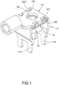
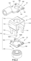
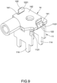
- the connecting terminal fixing structure 10 comprises: a conductive seat 11, a clamping member 12, and a nut 13; the conductive seat 11 consisting of two side plates 112 and a top plate 111 that are integrally formed, the top plate 111 being connected to the top of the side plate 112 on each side so that the conductive seat 11 forms an n-shape, and the top plate 111 having a perforation 113; the clamping member 12 having an opening 121 and being located on the lower surface of the top plate 111, the clamping member 12 having two snap-fitting parts 122 extending from each of the two opposite sides; the nut 13 having a threaded hole 131 whose inner wall is provided with a thread; wherein the perforation 113, the opening 121, and the threaded hole 131 are positioned correspondingly to form a through hole 20; wherein the snap-fitting part 122 is contacted and connected to
- the clamping member 12 is located on the lower surface of the top plate 111, and the snap-fitting parts 122 on two opposite sides of the clamping member 12 extend to both sides of the top plate 111 above.
- the snap-fitting part 122 is an elastic piece 122, and the position of the elastic piece 122 corresponds to the position of a notch 141 in a flat part 142 of the terminal 14, and the number of the elastic pieces 122 and the notches 141 are the same.
- the elastic piece 122 has a guiding surface 1221 and a protruding limit part 1222, the guiding surface 1221 is provided at the open end of the elastic piece 122 and is located above the outer edge of the terminal 14, the protruding limit part 1222 protrudes into the notch 141 and contacts with the surface of the notch 141, and the surface of the notch 141 is an inclined surface.
- the terminal 14 can smoothly slide into between the opposite sides of the elastic piece 122 and be snapped at the position of the protruding limit part 1222 so that the surface of the notch 141 of the terminal 14 can contact the protruding limit part 1222, thereby enabling the terminal 14 to be limited and fixed, so that the flat part 142 of the terminal 14 is closely connected to the conductive seat 11, and the connection hole 143 on the terminal 14 is also aligned with the through hole 20, so that the screw can be used to quickly lock the terminal 14 and the conductive seat 11 through the connection hole 143 and the through hole 20, thereby enabling the terminal 14 to be connected to the conductive seat 11 as a second layer of locking measures.
- each side plate 112 has at least one pin 114, so that the conductive seat 11 can be inserted on the PCB, in this embodiment, each side plate 112 has two pins 114.
- the clamping member 12 has an elastic piece 122 extending from each of two opposite sides, and each elastic piece 122 clamps to a notch 141 on each side of the terminal 14.
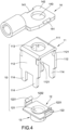
- the side plate 112 has at least one inclined part 1121 near the top plate 111.
- one side plate 112 has two inclined parts 1121, the inclined part 1121 is inclined toward the opposite side plate 112, and the upper end of the inclined part 1121 is against the lower surface of the clamping member 12. Therefore, when the clamping member 12 is placed on the lower surface of the top plate 111, the inclined part 1121 can be held against the lower surface of the clamping member 12, so that the clamping member 12 can be fixed more closely to the lower surface of the top plate 111 and would not easily fall off due to the gravity.
- the clamping member 12 and the nut 13 are integrally formed, so that one assembly process can be reduced.
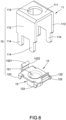
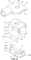
- FIGS. 5 to 6 which illustrate the third embodiment of the connecting terminal fixing structure 10 of the present disclosure, wherein at least one projection part 123 extends from each of the two opposite sides of the clamping member 12, in this embodiment, two projection parts 123 extend from each of the two opposite sides of the clamping member 12, when the clamping member 12 is placed on the lower surface of the top plate 111, the projection part 123 contacts the junction of the top plate 111 and the side plate 112 so that the clamping member 12 is closely fixed to the lower surface of the top plate 111 and is difficult to be moved, thereby strengthening the joint stability between the clamping member 12 and the conductive seat 11.
- the notch 141 of the terminal 14 is an inner concave rectangle, and the protruding limiter 1222 of the elastic piece 122 clamps with the notch 141 in a large area to enhance the tightness of the elastic piece 122 clamping the terminal 14.
- one side plate 112 has three inclined parts 1121 which are inclined toward the opposite side plate 112, and more inclined parts 1121 can hold the clamping member 12 more securely without moving or falling off due to gravity when the clamping member 12 is placed on the lower surface of the top plate 111.
- the conductive seat 11 on the PCB can be quickly aligned with the position of the terminal 14 and securely connected to the positioning screw hole, thereby reducing the assembly time and material used, and achieving optimal contact performance and reliability over a large area.
- the conductive seat 11 and the terminal 14 are not only fastened by bolts, but the clamping member 12 also provides a second layer of tight clamping mechanism which prevents the problem of the displacement between the conductive seat 11 and the terminal 14 due to loosening by vibration during transportation.
Landscapes
- Connections Arranged To Contact A Plurality Of Conductors (AREA)
- Connections By Means Of Piercing Elements, Nuts, Or Screws (AREA)
- Connections Effected By Soldering, Adhesion, Or Permanent Deformation (AREA)
Applications Claiming Priority (1)
| Application Number | Priority Date | Filing Date | Title |
|---|---|---|---|
| TW112204329U TWM644289U (zh) | 2023-05-05 | 2023-05-05 | 連接端子固定結構 |
Publications (1)
| Publication Number | Publication Date |
|---|---|
| EP4459798A1 true EP4459798A1 (fr) | 2024-11-06 |
Family
ID=88148962
Family Applications (1)
| Application Number | Title | Priority Date | Filing Date |
|---|---|---|---|
| EP23213914.7A Withdrawn EP4459798A1 (fr) | 2023-05-05 | 2023-12-04 | Structure de fixation de borne de connexion |
Country Status (3)
| Country | Link |
|---|---|
| US (1) | US20240372285A1 (fr) |
| EP (1) | EP4459798A1 (fr) |
| TW (1) | TWM644289U (fr) |
Families Citing this family (1)
| Publication number | Priority date | Publication date | Assignee | Title |
|---|---|---|---|---|
| CN119905831B (zh) * | 2025-04-01 | 2025-07-25 | 国网浙江省电力有限公司嵊泗县供电公司 | 一种接地挂环 |
Citations (3)
| Publication number | Priority date | Publication date | Assignee | Title |
|---|---|---|---|---|
| US9093761B1 (en) * | 2014-03-12 | 2015-07-28 | Dinkle Enterprise Co., Ltd. | Terminal block structure |
| US9520658B1 (en) * | 2016-01-28 | 2016-12-13 | Deere & Company | Fastener assembly |
| WO2022103130A1 (fr) * | 2020-11-13 | 2022-05-19 | 주식회사 엘지에너지솔루션 | Bloc-batterie, dispositif électronique, automobile et module de système de gestion de batterie |
Family Cites Families (4)
| Publication number | Priority date | Publication date | Assignee | Title |
|---|---|---|---|---|
| US3609654A (en) * | 1970-02-02 | 1971-09-28 | William H Wallo | Snap-in electrical connector |
| US4361371A (en) * | 1980-12-08 | 1982-11-30 | Amf Incorporated | Packaging of solid state relay |
| US5795193A (en) * | 1996-10-23 | 1998-08-18 | Yazaki Corporation | Power distribution box with busbar having bolt retaining means |
| JP6488688B2 (ja) * | 2014-12-17 | 2019-03-27 | ダイキン工業株式会社 | モジュール−端子台接続構造及び接続方法 |
-
2023
- 2023-05-05 TW TW112204329U patent/TWM644289U/zh unknown
- 2023-12-04 EP EP23213914.7A patent/EP4459798A1/fr not_active Withdrawn
- 2023-12-08 US US18/534,156 patent/US20240372285A1/en active Pending
Patent Citations (4)
| Publication number | Priority date | Publication date | Assignee | Title |
|---|---|---|---|---|
| US9093761B1 (en) * | 2014-03-12 | 2015-07-28 | Dinkle Enterprise Co., Ltd. | Terminal block structure |
| US9520658B1 (en) * | 2016-01-28 | 2016-12-13 | Deere & Company | Fastener assembly |
| WO2022103130A1 (fr) * | 2020-11-13 | 2022-05-19 | 주식회사 엘지에너지솔루션 | Bloc-batterie, dispositif électronique, automobile et module de système de gestion de batterie |
| US20230361364A1 (en) * | 2020-11-13 | 2023-11-09 | Lg Energy Solution, Ltd. | Battery pack, electronic device, vehicle and bms module |
Also Published As
| Publication number | Publication date |
|---|---|
| US20240372285A1 (en) | 2024-11-07 |
| TWM644289U (zh) | 2023-07-21 |
Similar Documents
| Publication | Publication Date | Title |
|---|---|---|
| JP2655081B2 (ja) | 電気コネクタおよびその回路基板への取付け方法 | |
| JP3040793U (ja) | 電気コネクタのプリント回路基板取付装置 | |
| JPH10134909A (ja) | コネクタ | |
| US10727621B1 (en) | Electrical connector system for LED tape lighting | |
| CN101317307A (zh) | 连接器防脱座、连接器保持件、连接器防脱构造、增强型装置侧连接器及fa设备 | |
| US20030166348A1 (en) | Contact guide retention apparatus | |
| EP4459798A1 (fr) | Structure de fixation de borne de connexion | |
| US20130295799A1 (en) | Inter-terminal connection structure | |
| US9236672B2 (en) | Holding metal fitting, connector coupler, and connector | |
| US6739880B2 (en) | Circuit board-to-board interconnection device | |
| KR100800216B1 (ko) | 커넥터 | |
| CN212485679U (zh) | 浮动式导引插入连接器 | |
| US20090075493A1 (en) | Electrical connector with fastening structure | |
| US5423696A (en) | Shield connector | |
| CN211789620U (zh) | 背面紧固式连接模块和控制盒 | |
| US8605454B2 (en) | Electronic device | |
| CN219959512U (zh) | 连接端子固定结构 | |
| JP5459195B2 (ja) | 回路構成体および電気接続箱 | |
| CN208189806U (zh) | 具有锁扣把手的端子座 | |
| CN104916898A (zh) | 天线装置 | |
| CN211150983U (zh) | 一种接插件 | |
| US11631951B2 (en) | Plug electrical connector and receptacle electrical connector | |
| US9461380B2 (en) | Connector and connecting port assembly therewith | |
| US7239529B1 (en) | Fixing member for auxiliary circuit board | |
| CN110061374B (zh) | 板对板连接器的限位支架及移动终端 |
Legal Events
| Date | Code | Title | Description |
|---|---|---|---|
| PUAI | Public reference made under article 153(3) epc to a published international application that has entered the european phase |
Free format text: ORIGINAL CODE: 0009012 |
|
| STAA | Information on the status of an ep patent application or granted ep patent |
Free format text: STATUS: THE APPLICATION HAS BEEN PUBLISHED |
|
| AK | Designated contracting states |
Kind code of ref document: A1 Designated state(s): AL AT BE BG CH CY CZ DE DK EE ES FI FR GB GR HR HU IE IS IT LI LT LU LV MC ME MK MT NL NO PL PT RO RS SE SI SK SM TR |
|
| STAA | Information on the status of an ep patent application or granted ep patent |
Free format text: STATUS: THE APPLICATION IS DEEMED TO BE WITHDRAWN |
|
| 18D | Application deemed to be withdrawn |
Effective date: 20250507 |