EP4459789A1 - Antenne für eine rfid-lesevorrichtung mit umschaltung der polarisation - Google Patents
Antenne für eine rfid-lesevorrichtung mit umschaltung der polarisation Download PDFInfo
- Publication number
- EP4459789A1 EP4459789A1 EP23171296.9A EP23171296A EP4459789A1 EP 4459789 A1 EP4459789 A1 EP 4459789A1 EP 23171296 A EP23171296 A EP 23171296A EP 4459789 A1 EP4459789 A1 EP 4459789A1
- Authority
- EP
- European Patent Office
- Prior art keywords
- antenna
- feed
- polarization
- switching element
- feed points
- Prior art date
- Legal status (The legal status is an assumption and is not a legal conclusion. Google has not performed a legal analysis and makes no representation as to the accuracy of the status listed.)
- Granted
Links
Images



Classifications
-
- H—ELECTRICITY
- H01—ELECTRIC ELEMENTS
- H01Q—ANTENNAS, i.e. RADIO AERIALS
- H01Q15/00—Devices for reflection, refraction, diffraction or polarisation of waves radiated from an antenna, e.g. quasi-optical devices
- H01Q15/24—Polarising devices; Polarisation filters
- H01Q15/242—Polarisation converters
-
- H—ELECTRICITY
- H01—ELECTRIC ELEMENTS
- H01Q—ANTENNAS, i.e. RADIO AERIALS
- H01Q1/00—Details of, or arrangements associated with, antennas
- H01Q1/50—Structural association of antennas with earthing switches, lead-in devices or lightning protectors
-
- G—PHYSICS
- G06—COMPUTING OR CALCULATING; COUNTING
- G06K—GRAPHICAL DATA READING; PRESENTATION OF DATA; RECORD CARRIERS; HANDLING RECORD CARRIERS
- G06K19/00—Record carriers for use with machines and with at least a part designed to carry digital markings
- G06K19/06—Record carriers for use with machines and with at least a part designed to carry digital markings characterised by the kind of the digital marking, e.g. shape, nature, code
- G06K19/067—Record carriers with conductive marks, printed circuits or semiconductor circuit elements, e.g. credit or identity cards also with resonating or responding marks without active components
- G06K19/07—Record carriers with conductive marks, printed circuits or semiconductor circuit elements, e.g. credit or identity cards also with resonating or responding marks without active components with integrated circuit chips
- G06K19/0723—Record carriers with conductive marks, printed circuits or semiconductor circuit elements, e.g. credit or identity cards also with resonating or responding marks without active components with integrated circuit chips the record carrier comprising an arrangement for non-contact communication, e.g. wireless communication circuits on transponder cards, non-contact smart cards or RFIDs
-
- G—PHYSICS
- G06—COMPUTING OR CALCULATING; COUNTING
- G06K—GRAPHICAL DATA READING; PRESENTATION OF DATA; RECORD CARRIERS; HANDLING RECORD CARRIERS
- G06K7/00—Methods or arrangements for sensing record carriers, e.g. for reading patterns
- G06K7/10—Methods or arrangements for sensing record carriers, e.g. for reading patterns by electromagnetic radiation, e.g. optical sensing; by corpuscular radiation
- G06K7/10009—Methods or arrangements for sensing record carriers, e.g. for reading patterns by electromagnetic radiation, e.g. optical sensing; by corpuscular radiation sensing by radiation using wavelengths larger than 0.1 mm, e.g. radio-waves or microwaves
- G06K7/10316—Methods or arrangements for sensing record carriers, e.g. for reading patterns by electromagnetic radiation, e.g. optical sensing; by corpuscular radiation sensing by radiation using wavelengths larger than 0.1 mm, e.g. radio-waves or microwaves using at least one antenna particularly designed for interrogating the wireless record carriers
-
- H—ELECTRICITY
- H01—ELECTRIC ELEMENTS
- H01P—WAVEGUIDES; RESONATORS, LINES, OR OTHER DEVICES OF THE WAVEGUIDE TYPE
- H01P1/00—Auxiliary devices
- H01P1/10—Auxiliary devices for switching or interrupting
-
- H—ELECTRICITY
- H01—ELECTRIC ELEMENTS
- H01P—WAVEGUIDES; RESONATORS, LINES, OR OTHER DEVICES OF THE WAVEGUIDE TYPE
- H01P5/00—Coupling devices of the waveguide type
- H01P5/12—Coupling devices having more than two ports
- H01P5/16—Conjugate devices, i.e. devices having at least one port decoupled from one other port
- H01P5/18—Conjugate devices, i.e. devices having at least one port decoupled from one other port consisting of two coupled guides, e.g. directional couplers
-
- H—ELECTRICITY
- H01—ELECTRIC ELEMENTS
- H01P—WAVEGUIDES; RESONATORS, LINES, OR OTHER DEVICES OF THE WAVEGUIDE TYPE
- H01P5/00—Coupling devices of the waveguide type
- H01P5/12—Coupling devices having more than two ports
- H01P5/16—Conjugate devices, i.e. devices having at least one port decoupled from one other port
- H01P5/19—Conjugate devices, i.e. devices having at least one port decoupled from one other port of the junction type
- H01P5/20—Magic-T junctions
-
- H—ELECTRICITY
- H01—ELECTRIC ELEMENTS
- H01Q—ANTENNAS, i.e. RADIO AERIALS
- H01Q1/00—Details of, or arrangements associated with, antennas
- H01Q1/12—Supports; Mounting means
- H01Q1/22—Supports; Mounting means by structural association with other equipment or articles
- H01Q1/2208—Supports; Mounting means by structural association with other equipment or articles associated with components used in interrogation type services, i.e. in systems for information exchange between an interrogator/reader and a tag/transponder, e.g. in Radio Frequency Identification [RFID] systems
-
- H—ELECTRICITY
- H01—ELECTRIC ELEMENTS
- H01Q—ANTENNAS, i.e. RADIO AERIALS
- H01Q1/00—Details of, or arrangements associated with, antennas
- H01Q1/12—Supports; Mounting means
- H01Q1/22—Supports; Mounting means by structural association with other equipment or articles
- H01Q1/2208—Supports; Mounting means by structural association with other equipment or articles associated with components used in interrogation type services, i.e. in systems for information exchange between an interrogator/reader and a tag/transponder, e.g. in Radio Frequency Identification [RFID] systems
- H01Q1/2216—Supports; Mounting means by structural association with other equipment or articles associated with components used in interrogation type services, i.e. in systems for information exchange between an interrogator/reader and a tag/transponder, e.g. in Radio Frequency Identification [RFID] systems used in interrogator/reader equipment
-
- H—ELECTRICITY
- H01—ELECTRIC ELEMENTS
- H01Q—ANTENNAS, i.e. RADIO AERIALS
- H01Q15/00—Devices for reflection, refraction, diffraction or polarisation of waves radiated from an antenna, e.g. quasi-optical devices
- H01Q15/24—Polarising devices; Polarisation filters
-
- H—ELECTRICITY
- H01—ELECTRIC ELEMENTS
- H01Q—ANTENNAS, i.e. RADIO AERIALS
- H01Q21/00—Antenna arrays or systems
- H01Q21/24—Combinations of antenna units polarised in different directions for transmitting or receiving circularly and elliptically polarised waves or waves linearly polarised in any direction
- H01Q21/245—Combinations of antenna units polarised in different directions for transmitting or receiving circularly and elliptically polarised waves or waves linearly polarised in any direction provided with means for varying the polarisation
-
- H—ELECTRICITY
- H01—ELECTRIC ELEMENTS
- H01Q—ANTENNAS, i.e. RADIO AERIALS
- H01Q5/00—Arrangements for simultaneous operation of antennas on two or more different wavebands, e.g. dual-band or multi-band arrangements
- H01Q5/20—Arrangements for simultaneous operation of antennas on two or more different wavebands, e.g. dual-band or multi-band arrangements characterised by the operating wavebands
- H01Q5/28—Arrangements for establishing polarisation or beam width over two or more different wavebands
-
- H—ELECTRICITY
- H01—ELECTRIC ELEMENTS
- H01Q—ANTENNAS, i.e. RADIO AERIALS
- H01Q9/00—Electrically-short antennas having dimensions not more than twice the operating wavelength and consisting of conductive active radiating elements
- H01Q9/04—Resonant antennas
- H01Q9/0407—Substantially flat resonant element parallel to ground plane, e.g. patch antenna
- H01Q9/0428—Substantially flat resonant element parallel to ground plane, e.g. patch antenna radiating a circular polarised wave
-
- H—ELECTRICITY
- H01—ELECTRIC ELEMENTS
- H01Q—ANTENNAS, i.e. RADIO AERIALS
- H01Q9/00—Electrically-short antennas having dimensions not more than twice the operating wavelength and consisting of conductive active radiating elements
- H01Q9/04—Resonant antennas
- H01Q9/0407—Substantially flat resonant element parallel to ground plane, e.g. patch antenna
- H01Q9/0428—Substantially flat resonant element parallel to ground plane, e.g. patch antenna radiating a circular polarised wave
- H01Q9/0435—Substantially flat resonant element parallel to ground plane, e.g. patch antenna radiating a circular polarised wave using two feed points
-
- H—ELECTRICITY
- H01—ELECTRIC ELEMENTS
- H01Q—ANTENNAS, i.e. RADIO AERIALS
- H01Q9/00—Electrically-short antennas having dimensions not more than twice the operating wavelength and consisting of conductive active radiating elements
- H01Q9/04—Resonant antennas
- H01Q9/0407—Substantially flat resonant element parallel to ground plane, e.g. patch antenna
- H01Q9/045—Substantially flat resonant element parallel to ground plane, e.g. patch antenna with particular feeding means
Definitions
- the invention relates to an antenna for an RFID reading device and a method for switching the polarization of an antenna according to the preamble of claims 1 and 15 respectively.
- RFID readers are used to identify objects and goods and are used, among other things, to automate logistical movements. At an identification point, especially when the owner of the goods changes or the means of transport changes, RFID transponders attached to the goods are read and, if necessary, information is written back into the transponder. The information recorded is used to control the forwarding and sorting of goods and products.
- Important applications for automatic identification are logistical distribution centers, for example those of parcel senders, or baggage drop-off at airports.
- the RFID reader uses its antenna to stimulate RFID transponders in its reading range to emit the stored information using electromagnetic radiation, receives the corresponding transponder signals and evaluates them.
- the UHF frequency range (ultra high frequency) is often used for this purpose, as there is an established framework in the ISO 18000-6 standard and transponders can also be read at different distances from a few millimeters to several meters.
- UHF RFID transponders are available in very compact designs and can therefore also be attached to very small objects.
- the orientation of the RFID transponder with respect to the RFID reader is not fixed or at least not known.
- the DE 20 2015 106 025 U1 discloses an RFID antenna arrangement for receiving and transmitting electromagnetic waves of different polarization.
- the antenna has two feed points in its basic form. This already means that the circuit complexity is high, especially for controlling the mixer used, and there are relatively large losses in the feed network. However, only with four feed points are favorable antenna properties achieved, especially with regard to the axis ratio, which, for example, create robustness against interference from metallic objects in the direct vicinity of the antenna.
- the DE 20 2015 106 025 U1 A circuit variant for four feed points was also presented. However, it is based on doubling the feed network for two feed points, which significantly exacerbates the disadvantages mentioned above.
- the US 7 068 224 B2 reveals a patch antenna that can be switched between vertical and linear polarization. This means that there is no possibility of circular polarization.
- An antenna arrangement according to EP3220554A1 can switch between different polarizations, but uses one horizontally linear and one vertically linear polarized antenna.
- the feed network could also not be used for four feed points.
- the KR 10 0976087 B1 discloses another antenna arrangement for selectively generating linear and circular polarization.
- the feed network used controls four feed points, but is not able to compensate for mismatches that occur at the patch antenna.
- An antenna network according to EP 2 368 210 B1 is able to operate an antenna with circular or elliptical polarization so that it is alternately polarized left-handed and right-handed.
- linear polarization is not possible.
- EP 1 987 468 B1 describes an RFID multiplexer that distributes an RFID signal to different antennas. There is no possibility of generating different polarizations within one antenna.
- the DE 20 2015 105 455 U1 presents a conductor structure for an RFID signal, which is composed of straight line sections on the edges of a hexagonal grid. The document does not deal with the switching of polarizations.
- an antenna for an RFID reading device and a method for switching the polarization of an antenna according to claim 1 and 15 respectively.
- the antenna has an antenna element with which a signal is emitted or received.
- Four feed points are provided on the antenna element
- a feed network connects an input signal to the feed points in such a way that an antenna with either circular or linear polarization is created. Depending on the polarization state, all feed points or only a subset of them are fed.
- the invention is based on the basic idea of setting different switching states in the feed network using a circuit arrangement.
- the switching states each correspond to a polarization.
- four polarizations are of interest for an RFID reader, namely horizontal-linear polarization, vertical-linear polarization, right-handed circular polarization and left-handed circular polarization.
- the feed network enables switching states for at least three of these four polarizations. In the respective switching state, it is ensured that the feed points are each fed with a signal of a phase and power derived from the input signal, from which the selected polarization results overall. For some polarizations and feed points, this can mean that no signal should be present.
- the feed network can therefore output different power levels with different phase angles to each other at different outputs, with the powers and phases generating the associated polarization via the feed points on the antenna element depending on the switching state.
- the invention has the advantage that it enables the antenna to be operated with the optimum polarization for the application situation and the RFID transponders to be read.
- the feed network according to the invention is able to couple the input signal into the four feed points with particularly low losses. The lower the losses for signal division and forwarding, the higher the antenna gain. With RFID antennas, this has a double effect because the same antenna is used for transmission and reception. Overall, this increases the reading rate and the range.
- the feed points are preferably arranged symmetrically, especially in a square. This ensures particularly favorable antenna and polarization properties and a clear, simple structure.
- the circuit arrangement preferably has a first switching element and a second switching element with a plurality of connecting lines between them, in particular four connecting lines.
- a two-stage switch structure creates even low complexity provides sufficient flexibility to generate the different polarizations.
- a 90° hybrid coupler is preferably provided in the connecting lines between the first switching element and the second switching element, in particular in two of the connecting lines.
- the 90° hybrid coupler can thus be optionally included in the feed depending on the switching state.
- a 90° phase is used for the circular polarizations.
- the connecting lines with the 90° hybrid conductor can be bypassed by an associated switching state, which leads to better adaptation of the antenna.
- the first switching element preferably has at least one connection for the input signal on an input side and four connections on an output side towards the antenna element.
- the first switching element thus makes the input signal available in a switchable manner at one of four outputs, with the four outputs preferably being connected to the four connecting lines. In one embodiment, this is a 1:4 assignment.
- the first switching element particularly preferably has a further connection on the input side, which is connected to an antenna termination. This then results in an embodiment with a 2:4 assignment.
- the included antenna termination ensures significantly improved antenna matching.
- the first switching element is preferably designed as a four-way switch, in particular DP4T (Double Pole Quadruple Throw), or as a combination of changeover switches, in particular a DPDT (Double Pole Double Throw) with two downstream SPDTs (Single Pole Double Throw).
- DP4T Double Pole Quadruple Throw
- DPDT Double Pole Double Throw
- SPDTs Single Pole Double Throw
- the first switching element preferably has a connection for the input signal on an input side and three connections on an output side towards the antenna element, with the 90° hybrid coupler being permanently connected to an antenna termination.
- the antenna termination is permanently assigned to the switching state in which the 90° hybrid coupler is included, so that two connections are not required on the input side.
- the direction of rotation of the circular polarization can be selected in terms of circuitry by which side the 90° hybrid coupler is connected to the first switching element or the antenna termination; swapping the two leads to a reversal of the direction of rotation.
- a concrete example of a switch module for this embodiment is an SP3T (Single Pole Triple Throw).
- DPDT upstream 2:2 switch
- SP4T four-way switches
- the second switching element preferably has two changeover switches, with which in particular one of two connecting lines can be selectively switched through to the antenna element.
- the two changeover switches in particular SPDT, are connected in pairs in particular on the input side to the four connecting lines from the first switching element, so that in each case a pair of connecting lines is connected in a 2:1 assignment to an output-side line of the changeover switch directed to the feed points.
- the respective pair is preferably formed by a direct connecting line of the first switching element and a connecting line routed via the 90° hybrid coupler. It should be mentioned that in the aforementioned embodiment with a first switching element with a 1:3 assignment there is also a fourth connecting line, namely the one from the antenna termination on the 90° hybrid coupler.
- the feed network preferably has two 180° power dividers, of which one 180° power divider is connected to two feed points and the other 180° power divider is connected to the remaining two feed points in order to feed the respective two connected feed points with partial signals of the input signal that are 180° out of phase.
- the 180° power dividers split the incoming signal and feed the partial signals with a respective 180° phase offset to their assigned feed points.
- the two pairs of feed points form the diagonals in the arrangement of the feed points.
- one 180° power divider is connected to each of the changeover switches of the second switching element.
- the 180° power dividers are preferably designed as hybrid ring couplers (ratrace hybrid). This is a proven and suitable circuit element for generating two partial signals with a mutual 180° phase offset from one signal.
- the 180° power dividers are designed as Wilkinson dividers or T-power dividers. The 180° phase offset is then generated in particular by means of a delay line for one of the partial signals in the connection between the Wilkinson divider or T-power divider and the feed point.
- the feed network is preferably designed without crossings. This is possible through clever geometric arrangement, in particular by using the line structure based on hexagonal honeycombs according to the DE 20 2015 105 455 U1 A feed network without crossings can be manufactured in a single layer, without changing the circuit board or PCB layer. This results in a particularly cost-effective and easy-to-handle component.
- the antenna preferably has a circuit board, on one surface of which the antenna element is arranged and on the other surface of which the feed network is arranged. This results in a particularly compact design. This is particularly advantageous with a feed network without crossings as described in the previous paragraph. A simple circuit board is then sufficient; no complex multi-layer structure is required.
- the antenna element is preferably designed as an antenna patch, because such a patch can also be applied flat and in one layer. This creates a very compact patch antenna with good antenna properties and the option of choosing between up to four polarizations.
- an RFID reading device has an antenna according to the invention, a transceiver connected to the antenna and an RFID control and evaluation unit connected to the transceiver.
- the antenna can be operated as an internal or external antenna of the RFID reading device.
- the antenna is used by the RFID reading device to send RFID signals to an RFID transponder and/or to receive RFID signals from an RFID transponder. Any combination of a transmitter and receiver is referred to as a transceiver here.
- the RFID control and evaluation unit which has at least one digital Computing component, such as a microprocessor, an FPGA (Field Programmable Gate Array), an ASIC (Application Specific Integrated Circuit) or the like, is designed for encoding RFID information in the RFID signals and/or for reading RFID information from the RFID signals.
- the transceiver and RFID control and evaluation unit can form a common computing component or at least partially use a computing component together.
- Such an RFID reading device is preferably used in stationary installation on a reading area of a conveyor or a reading portal for reading at least one RFID transponder moved on the conveyor or through the reading portal.
- a suitable polarization can be set and this can also be changed dynamically during operation.
- FIG. 1 shows a schematic representation of an antenna 10 in an RFID reading device 12.
- the antenna 10 is designed, for example, for the ISM band at around 900 MHz.
- a transceiver 14 is connected to the antenna 10 and to this a control and evaluation unit 16 of the RFID reading device 12 in order to evaluate RFID signals received by the antenna 10 or to send information as RFID signals to a transponder.
- the control and evaluation unit 16 is also connected to a wired or wireless interface 18 in order to exchange data, carry out parameterization and the like.
- an RFID reader for example for the UHF frequency range (ultra high frequency) according to the ISO 18000-6 standard, is known per se and is therefore not explained in more detail.
- the invention relates to the antenna 10 or its feed network, as described below with reference to the further Figures 2 to 10 described in detail.
- an external antenna is also conceivable, in which case the transceiver 14 and the control and evaluation unit 16 are accommodated in at least one further housing that is separate from the antenna 10 and connected via a cable.
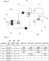
- FIG. 2 shows a schematic representation of a feed network for the antenna 10.
- the feed network has the function of dividing the input signal 20 and coupling it with suitable power levels and phases at four feed points P1... P4 into an antenna element 22, so that an antenna 10 with the desired polarization is created.
- the antenna element 22 is preferably an antenna patch, so that a patch antenna is created.
- a horizontal-linear polarization, a vertical-linear polarization, a right-handed circular polarization and a left-handed circular polarization are possible, i.e. four polarizations.
- the presented embodiment of the feed network only allows one circular polarization and thus three polarizations.
- the feed network has a first switching element 24, in the example shown a four-way switch with two input-side connections (DP4T, Double Pole Quadruple Throw), with which the input signal 20 is distributed to four connections.
- An antenna termination 26 is provided on the second input-side connection.
- the first switching element 24 is followed by a second switching element 28, which has, for example, two single-pole changeover switches (SPOT, Single Pole Double Throw).
- SPOT Single Pole Double Throw
- Four connecting lines from the four output-side connections of the first switching element 24 to the second switching element 28 are connected in pairs to the input-side connections of the single-pole changeover switches.
- a 90° hybrid coupler 30 is connected in one connecting line of each pair (Branchline Hybrid, 90° 3dB Divider).
- Two 180° power dividers 32 are connected to the output of the second switching element 28, in this embodiment as a ring coupler (ratrace hybrid, 180° 3dB divider), each of which has its own termination 34.
- each of the two partial signals is split again by the two single-pole changeover switches of the second switching element 28, and the resulting partial signals are fed to the feed points P1, P3 and P2, P4 with a 180° phase offset.
- FIG 3 shows an alternative representation of the feed network according to Figure 2 .
- the feed points P1...P4 are also arranged symmetrically, preferably in the form of a centered square.
- a phase offset of 90° for circular polarization or 180° for linear polarization is required, as provided by the feed network.
- a different, non-symmetrical arrangement is possible, but then requires a corresponding adjustment of the phases or only achieves the desired polarization approximately.
- Figure 4 shows a table with polarizations and associated switch positions of the feed network. The different polarizations are entered in the first column.
- the variants "Open 1" and “Open 2" are special cases that are not required for the actual operation of the antenna 10.
- the explicit wiring of the input signal 20 to an open or shorted to ground line end can be used, for example, for a reference measurement or calibration in order to measure the distance between the RFID front end with the transceiver 14 and the feed network. characterize, for example, to determine the line attenuation for remote antennas with longer cables.
- the second column shows how, for a respective polarization state of the first column, the input-side connections P1, P2 of the first switching element 24 are connected to its output-side connections P3... P6.
- the third and fourth columns show the switching state of the two single-pole changeover switches 28a-b of the second switching element 28. It should be noted that the designations Px are used several times for connections of different switching elements and also the feed points, but it is clear from the respective context what the designation refers to.
- the last four columns list the signals arriving at the feed points P1... P4, whereby the feed points in the table are as already in Figure 3 are designated out1... out4. Pin represents the respective input power.
- the first circular polarization according to the first line of the table is achieved in that the first switching element 24 establishes a connection to the inner connecting lines with the 90° hybrid coupler via P4 and P5, while the second switching element 28 passes these inner connecting lines via P3 of the first single-pole changeover switch 28a and P2 of the second single-pole changeover switch 28b to the 180° power dividers 32.
- the two partial signals output from the second switching element 28 are thus phase-shifted by 90° to one another, and the 180° power dividers thereby generate a 0° partial signal for the feed point P1, a 90° partial signal for P2, a 180° partial signal for P3 and a 270° partial signal for P4.
- the antenna 10 With its four feed points, the antenna 10 enables circular polarization with a low axial ratio. This makes the antenna 10 more robust against external interference, in particular metallic objects or reflectors near the antenna 10.
- partial signals with a phase offset of 180° can be coupled into two feed points. The attenuation is low for all polarizations. With linear polarization, the 90° hybrid coupler 30 is bypassed, so that the attenuation can remain even lower than with circular polarization.
- Figure 5 shows an exemplary concrete layout of the feed network on a circuit board or printed circuit board 38, which in Figure 3 is shown schematically.
- the antenna element 22 can be seen on the back of the circuit board 38.
- the structures of the 90° hybrid coupler 30 as well as those of the two 180° power dividers 32 use a conductor structure on a hexagonal grid according to the aforementioned DE 20 2015 105 455 U1 They are connected by means of connections implemented as impedance-matched microstrip lines 40.
- connecting lines 42 lead to the feed points P1 to P4, the symmetrical arrangement of which is shown in the associated schematic representation of the Figure 3 is even more recognizable.
- the special feature of the feed network shown is that it can be implemented in a single copper layer.
- the feed network does not require any crossings of the lines and therefore no change of the board layer and components required for line crossings, especially since corresponding crossings (vias) for impedance matching would require special attention in terms of attenuation and phase shift.
- a particularly compact design of the antenna 10 is created when the feed network is arranged on one side or surface of the circuit board 38 (bottom side), in particular in a single layer, and the antenna element 22 on the other side or surface (top side), in particular in the form of an antenna patch.
- Such an easily integrated structure also easily enables modular variant formation for different housings, as is the case in the as yet unpublished European patent application with the file number 22188151.9 described.
- Figure 6 shows a schematic representation of another embodiment of the supply network.
- the first switching element here is designed as a series arrangement of a two-pole changeover switch 24a (DPDT, Double Pole Double Throw) with two single-pole changeover switches 24b (SPOT, Single Port Double Throw).
- DPDT Double Pole Double Throw
- SPOT Single Port Double Throw
- FIG. 7 shows a schematic representation of another embodiment of the feed network.
- the first switching element provides additional connections 44 for a further antenna (not shown) in various switchable polarizations.
- two four-way switches SP4T
- DPDT two-pole changeover switch
- FIG 8 shows a schematic representation of another embodiment of the feed network.
- the 180° power dividers 32 are no longer designed as hybrid ring couplers, but as Wilkinson dividers 32a.
- the 180° phase offset is achieved by means of delay lines with a suitable delay.
- a Schiffmann phase shifter would be conceivable in order to enable power division with a suitable phase offset over a larger frequency range of the feed network.
- a 3dB 180° power division is also possible on the basis of the Wilkinson dividers 32a.
- the advantage over ring couplers is lower transmission loss when dimensioned correctly.
- the isolation between the output ports is lower, but this plays a minor role in the structure of the antenna 10, since the signals are to be coupled to the same antenna element 22 and there is a relatively good coupling between two opposite feed points, especially when designed as an antenna patch.
- Figure 9 shows another alternative to Figure 8 , in which the Wilkinson dividers 32a are now replaced by T-power dividers 32b. Otherwise, refer to the explanations for Figure 8
- the selection of suitable 180° power dividers 32, 32a, 32b is possible in all embodiments, this is not limited to the special representations of the Figures 8 and 9 limited.
- Figure 10 shows a schematic representation of another embodiment in which the feed network only supports one circular polarization and not both circular polarizations of both directions of rotation.
- the first switching element 24 used here is a three-way switch (SP3T, Single Pole Triple Throw). Only one connection to the 90° hybrid coupler 30 can be switched, the other connection is permanently connected to an antenna adapter 48. The direction of rotation of the circular polarization can only be selected by circuit design.
- the feed network according to Figure 10 allowed This means that there is only a choice between three polarizations and it has the advantage of generating lower losses due to the reduced number of switches and the simpler design of the switch components.
Landscapes
- Engineering & Computer Science (AREA)
- Physics & Mathematics (AREA)
- Health & Medical Sciences (AREA)
- Computer Networks & Wireless Communication (AREA)
- Toxicology (AREA)
- General Physics & Mathematics (AREA)
- Theoretical Computer Science (AREA)
- Microelectronics & Electronic Packaging (AREA)
- Computer Hardware Design (AREA)
- Electromagnetism (AREA)
- General Health & Medical Sciences (AREA)
- Artificial Intelligence (AREA)
- Computer Vision & Pattern Recognition (AREA)
- Variable-Direction Aerials And Aerial Arrays (AREA)
- Waveguide Aerials (AREA)
Abstract
Description
- Die Erfindung betrifft eine Antenne für eine RFID-Lesevorrichtung und ein Verfahren zum Umschalten der Polarisation einer Antenne nach dem Oberbegriff von Anspruch 1 beziehungsweise 15.
- RFID-Lesevorrichtungen dienen der Identifikation von Objekten und Waren und werden unter anderem eingesetzt, um logistische Bewegungen zu automatisieren. An einem Identifikationspunkt, vor allem bei einem Wechsel des Besitzers der Ware oder einem Wechsel des Transportmittels, werden an den Waren befestigte RFID-Transponder ausgelesen und gegebenenfalls Informationen in den Transponder zurückgeschrieben. Die erfassten Informationen werden verwendet, um die Weiterleitung und Sortierung von Gütern und Produkten zu steuern. Wichtige Anwendungen für die automatische Identifikation sind logistische Verteilerzentren, etwa von Paketversendern, oder die Gepäckaufgabe in Flughäfen.
- Die RFID-Lesevorrichtung regt über ihre Antenne durch elektromagnetische Strahlung in ihrem Lesebereich befindliche RFID-Transponder zur Abstrahlung der gespeicherten Information an, empfängt die entsprechenden Transpondersignale und wertet sie aus. Dazu wird häufig der UHF-Frequenzbereich (Ultrahochfrequenz) verwendet, da es hier in dem Standard ISO 18000-6 einen etablierten Rahmen gibt und zudem Transponder in unterschiedlichen Entfernungen von einigen Millimetern bis hin zu mehreren Metern ausgelesen werden können. UHF-RFID-Transponder sind in sehr kompakten Bauformen verfügbar und können dementsprechend auch an sehr kleinen Objekten angebracht werden.
- In vielen Anwendungen ist die Ausrichtung des RFID-Transponders bezüglich der RIFD-Lesevorrichtung nicht festgelegt oder zumindest nicht bekannt. Dann ist es für die Reichweite und Leserate von Vorteil, eine zirkular polarisierte Antenne zu verwenden, um eine Varianz in der Orientierung der RFID-Transponder auszugleichen. Da die meisten RFID-Transponder eine linear polarisierte Antenne einsetzen, wird jedoch selbst im besten Fall nur die Hälfte der empfangenen Energie aufgenommen. In Anwendungen mit fixer Ausrichtung des RFID-Transponders bezüglich der RIFD-Lesevorrichtung ist deshalb eine linear polarisierte Antenne passender Ausrichtung zu bevorzugen, da dann der RFID-Transponder deutlich mehr Energie aufnehmen kann, wodurch sich die Identifikationsreichweite entsprechend erhöht. Deshalb kann je nach Anwendungsfall der Einsatz einer RFID-Lesevorrichtung mit unterschiedlicher Polarisation in Betracht gezogen werden.
- Die
DE 20 2015 106 025 U1 offenbart eine RFID-Antennenanordnung zum Empfangen und Senden von elektromagnetischen Wellen unterschiedlicher Polarisation. Die Antenne weist in ihrer Grundform zwei Speisepunkte auf. Bereits damit ist der Schaltungsaufwand insbesondere für die Ansteuerung des verwendeten Mischers hoch, und es gibt relativ große Verluste in dem Speisenetzwerk. Erst mit vier Speisepunkten werden jedoch günstige Antenneneigenschaften erreicht, insbesondere im Hinblick auf das Achsenverhältnis, die beispielsweise Robustheit gegen Störungen durch metallische Objekte in der direkten Umgebung der Antenne schaffen. Zwar wird in derDE 20 2015 106 025 U1 auch eine Schaltungsvariante für vier Speisepunkte vorgestellt. Sie basiert aber auf einer Dopplung des Speisenetzwerks für zwei Speisepunkte, wodurch sich die genannten Nachteile sogar nochmals erheblich verschärfen. - In der
US 7 932 867 B2 werden Verfahren zur Veränderung der Antennenpolarisation beschrieben. Dazu sind mehrere Antennen vorgesehen, die wahlweise eingesetzt werden, und das erhöht den konstruktiven Aufwand und benötigten Bauraum erheblich. - Die
US 7 068 224 B2 offenbart eine Patchantenne, die zwischen vertikaler und linearer Polarisation umgeschaltet werden kann. Damit fehlt es an der Möglichkeit einer zirkularen Polarisation. - Aus der
US 2011/0032079 A1 ist eine Antennenschaltanordnung mit einer Anordnung von Zugangsleitungen bekannt, durch die ein Signalpfad gewählt werden kann, indem Verbindungen auf Masse geschaltet werden. Dadurch entsteht an den beiden Ausgangsanschlüssen ein Signal mit linearer oder zirkularer Polarisation. Es ist auf diese Weise nicht möglich, zirkulare Polarisation beider Drehrichtungen zu erzeugen. - Eine Antennenanordnung gemäß
EP3220554A1 kann zwischen verschiedenen Polarisationen umschalten, verwendet dafür jedoch je eine horizontal-linear und eine vertikallinear polarisierte Antenne. Das Speisenetzwerk könnte zudem nicht für vier Speisepunkte verwendet werden. - Die
KR 10 0976087 B1 - Ein Antennen-Netzwerk gemäß
EP 2 368 210 B1 ist in der Lage, eine Antenne zirkular oder elliptisch polarisiert so zu betreiben, dass sie wechselweise linksdrehend und rechtsdrehend polarisiert wird. Eine lineare Polarisation ist dabei jedoch nicht möglich. - In der
EP 1 987 468 B1 wird ein RFID-Multiplexer beschrieben, der ein RFID-Signal an unterschiedliche Antennen verteilt. Dabei besteht keine Möglichkeit, innerhalb einer Antenne unterschiedliche Polarisationen zu erzeugen. - Die
DE 20 2015 105 455 U1 stellt eine Leiterstruktur für ein RFID-Signal vor, die aus geradlinigen Leitungsabschnitten auf den Kanten eines hexagonalen Rasters zusammengesetzt ist. Mit der Umschaltung von Polarisationen befasst sich das Dokument nicht. - Die noch unveröffentlichte europäische Patentanmeldung mit dem Aktenzeichen
22188151.9 - Es ist daher Aufgabe der Erfindung, eine Antenne mit umschaltbarer Polarisation weiter zu verbessern.
- Diese Aufgabe wird durch eine Antenne für eine RFID-Lesevorrichtung und ein Verfahren zum Umschalten der Polarisation einer Antenne nach Anspruch 1 beziehungsweise 15 gelöst. Die Antenne weist ein Antennenelement auf, mit dem ein Signal abgestrahlt beziehungsweise empfangen wird. Auf dem Antennenelement sind vier Speisepunkte vorgesehen. Ein Speisenetzwerk verbindet ein Eingangssignal derart mit den Speisepunkten, dass wahlweise eine Antenne mit zirkularer oder linearer Polarisation entsteht. Je nach Polarisationszustand werden dabei alle Speisepunkte oder nur eine Teilauswahl davon gespeist.
- Die Erfindung geht von dem Grundgedanken aus, in dem Speisenetzwerk mittels einer Schaltungsanordnung verschiedene Schaltzustände einzustellen. Die Schaltzustände entsprechen jeweils einer Polarisation. Insgesamt sind für eine RFID-Lesevorrichtung vier Polarisationen von Interesse, nämlich horizontal-lineare Polarisation, vertikal-lineare Polarisation, rechtsdrehend zirkulare Polarisation und linksdrehend zirkulare Polarisation. Das Speisenetzwerk ermöglicht Schaltzustände für mindestens drei dieser vier Polarisationen. In dem jeweiligen Schaltzustand ist dafür gesorgt, dass die Speisepunkte jeweils mit einem aus dem Eingangssignal abgeleiteten Signal einer Phase und Leistungen gespeist werden, aus dem sich insgesamt die gewählte Polarisation ergibt. Für manche Polarisationen und Speisepunkte kann dies bedeuten, dass kein Signal anliegen soll. Das Speisenetzwerk kann also an unterschiedlichen Ausgängen unterschiedliche Leistungspegel mit zueinander unterschiedlichen Phasenwinkeln ausgeben, wobei die Leistungen und Phasen je nach Schaltzustand über die Speisepunkte an dem Antennenelement die zugehörige Polarisation erzeugen.
- Die Erfindung hat den Vorteil, dass ein Betrieb der Antenne mit jeweils für die Anwendungssituation und die zu lesenden RFI D-Transponder optimaler Polarisation ermöglicht wird. Das erfindungsgemäße Speisenetzwerk ist in der Lage, das Eingangssignal mit besonders geringen Verlusten in die vier Speisepunkte einzukoppeln. Je geringer wiederum die Verluste für Signalaufteilung und Weiterleitung sind, desto höher ist der Antennengewinn. Bei RFID-Antennen wirkt sich das sogar doppelt aus, weil dieselbe Antenne für den Sende- und Empfangsbetrieb genutzt wird. Insgesamt erhöhen sich damit die Leserate und die Reichweite.
- Die Speisepunkte sind bevorzugt symmetrisch angeordnet, insbesondere in einem Quadrat. Das sorgt für besonders günstige Antennen- und Polarisationseigenschaften und einen übersichtlichen, einfachen Aufbau.
- Die Schaltungsanordnung weist bevorzugt ein erstes Schaltelement und ein zweites Schaltelement mit einer Vielzahl von Verbindungsleitungen dazwischen auf, insbesondere vier Verbindungsleitungen. Durch eine zweistufige Schalterstruktur entsteht bei noch geringer Komplexität eine hinreichende Flexibilität, um die unterschiedlichen Polarisationen zu erzeugen.
- In den Verbindungsleitungen zwischen dem ersten Schaltelement und dem zweiten Schaltelement ist bevorzugt ein 90°-Hybridkoppler vorgesehen, insbesondere in zwei der Verbindungsleitungen. Der 90°-Hybridkoppler kann damit wahlweise je nach Schaltzustand in die Speisung einbezogen werden. Insbesondere wird eine 90°-Phase für die zirkularen Polarisationen verwendet. Bei linearer Polarisation können die Verbindungsleitungen mit dem 90°-Hybridleiter durch einen zugehörigen Schaltzustand umgangen werden, was zu einer besseren Anpassung der Antenne führt.
- Das erste Schaltelement weist bevorzugt auf einer Eingangsseite mindestens einen Anschluss für das Eingangssignal und auf einer Ausgangsseite hin zu dem Antennenelement vier Anschlüsse auf. Das erste Schaltelement stellt damit das Eingangssignal schaltbar an einem von vier Ausgängen zur Verfügung, wobei vorzugsweise die vier Ausgänge mit den vier Verbindungsleitungen verbunden sind. In einer Ausführungsform ist das eine 1:4-Zuordnung. Besonders bevorzugt weist das erste Schaltelement auf der Eingangsseite einen weiteren Anschluss auf, der mit einem Antennenabschluss verbunden ist. Das ergibt dann eine Ausführungsform mit einer 2:4-Zuordnung. Der einbezogene Antennenabschluss sorgt für eine deutlich verbesserte Antennenanpassung.
- Das erste Schaltelement ist bevorzugt als Vierwegeschalter, insbesondere DP4T (Double Pole Quadruple Throw), oder als Kombination von Wechselschaltern ausgebildet, insbesondere eines DPDT (Double Pole Double Throw) mit zwei nachgeschalteten SPDT (Single Pole Double Throw). Das sind konkrete einfache Schalterbausteine, die sich für eine 2:4-Zuordnung eignen. Eingangsseitig sind vorzugsweise das Eingangssignal und ein Antennenabschluss verbunden, ausgangsseitig die vier Verbindungsleitungen zu dem zweiten Schaltelement.
- Das erste Schaltelement weist bevorzugt auf einer Eingangsseite einen Anschluss für das Eingangssignal und auf einer Ausgangsseite hin zu dem Antennenelement drei Anschlüsse auf, wobei der 90°-Hybridkoppler fest mit einem Antennenabschluss verbunden ist. Das entspricht einer 1:3-Zuordnung und ist geeignet für eine Ausführungsform, die nur drei Polarisationen wählen lässt, nämlich die beiden linearen Polarisationen und eine zirkulare Polarisation, deren Drehrichtung durch das Speisenetzwerk festgelegt ist. Der Antennenabschluss ist hier fest dem Schaltzustand zugeordnet, in dem der 90°-Hybridkoppler einbezogen ist, so dass eingangsseitig keine zwei Anschlüsse benötigt werden. Die Drehrichtung der zirkularen Polarisation lässt sich schaltungstechnisch dadurch wählen, auf welcher Seite der 90°-Hybridkoppler mit dem ersten Schaltelement beziehungsweise dem Antennenabschluss verbunden ist; eine Vertauschung führt hier zu einer Umkehr der Drehrichtung. Ein konkreter beispielhafter Schalterbaustein für diese Ausführungsform ist ein SP3T (Single Pole Triple Throw).
- Das erste Schaltelement weist bevorzugt auf der Ausgangsseite zusätzliche Anschlüsse für ein weiteres Antennenelement auf. Dafür wird eine 1:n-Zuordnung mit n>4 benötigt, wie n=8 für den Anschluss einer weiteren Antenne mit vier wählbaren Polarisationen. Das lässt sich beispielsweise durch die Kombination eines vorgeordneten 2:2-Schalters (DPDT) und zweier Vierwegeschalter (SP4T) erreichen.
- Das zweite Schaltelement weist bevorzugt zwei Wechselschalter auf, mit denen insbesondere jeweils wahlweise eine von zwei Verbindungsleitungen zu dem Antennenelement durchschaltbar ist. Die beiden Wechselschalter, insbesondere SPDT, sind insbesondere eingangsseitig paarweise mit den vier Verbindungsleitungen von dem ersten Schaltelement verbunden, so dass jeweils in einer 2:1-Zuordnung ein Paar Verbindungsleitungen auf eine zu den Speisepunkten gerichtete ausgangsseitige Leitung der Wechselschalter verschaltet ist. Dabei wird das jeweilige Paar vorzugsweise von einer direkten Verbindungsleitung des ersten Schaltelements und einer über den 90°-Hybridkoppler geführten Verbindungsleitung gebildet. Es sei erwähnt, dass es auch in der genannten Ausführungsform mit einem ersten Schaltelement mit 1:3-Zuordnung eine vierte Verbindungsleitung gibt, nämlich diejenige von dem Antennenabschluss an dem 90°-Hybridkoppler.
- Das Speisenetzwerk weist bevorzugt zwei 180°-Leistungsteiler auf, von denen der eine 180°-Leistungsteiler mit zwei Speisepunkten und der andere 180°-Leistungsteiler mit den verbleibenden zwei Speisepunkten verbunden ist, um die jeweiligen zwei verbundenen Speisepunkte mit um 180° phasenversetzten Teilsignalen des Eingangssignals zu speisen. Die 180°-Leistungsteiler teilen das eingehende Signal auf und führen die Teilsignale mit jeweiligem 180°-Phasenversatz ihren zugeordneten Speisepunkten zu. Vorzugsweise bilden die beiden Paare von Speisepunkten die Diagonalen in der Anordnung der Speisepunkte. Vorzugsweise ist jeweils ein 180°-Leistungsteiler mit einem der Wechselschalter des zweiten Schaltelements verbunden.
- Die 180°-Leistungsteiler sind bevorzugt als Hybrid-Ringkoppler (Ratrace Hybrid) ausgebildet. Das ist ein bewährtes und geeignetes Schaltungselement, um aus einem Signal zwei Teilsignale mit gegenseitigem 180°-Phasenversatz zu erzeugen. Alternativ sind die 180°-Leistungsteiler als Wilkinson-Teiler oder T-Leistungsteiler ausgebildet. Der 180°-Phasenversatz wird dann insbesondere mittels einer Verzögerungsleitung für eines der Teilsignale in der Verbindung zwischen Wilkinson-Teiler oder T-Leistungsteiler und Speisepunkt erzeugt.
- Das Speisenetzwerk ist vorzugsweise ohne Kreuzungen ausgebildet. Das ist durch geschickte geometrische Anordnung möglich, insbesondere unter Ausnutzung der auf hexagonalen Waben beruhenden Leitungsstruktur gemäß der einleitend genannten
DE 20 2015 105 455 U1 . Ein Speisenetzwerk ohne Kreuzungen wiederum kann in einer einzigen Lage hergestellt werden, es ist dafür kein Wechsel des Leiterplatten- oder Platinenlayers erforderlich. Das führt zu einem besonders kostengünstigen und einfach zu handhabenden Bauteil. - Die Antenne weist bevorzugt eine Leiterplatte auf, auf deren einer Fläche das Antennenelement und auf deren anderer Fläche das Speisenetzwerk angeordnet ist. Das ergibt eine besonders kompakte Bauform. Besonders günstig ist dies mit einem Speisenetzwerk ohne Kreuzungen gemäß dem Vorabsatz. Es genügt dann eine einfache Leiterplatte, es ist kein komplexer mehrschichtiger Aufbau erforderlich. Das Antennenelement ist dabei bevorzugt als Antennenpatch ausgebildet, denn ein solcher Patch kann ebenfalls flach und in einer Schicht aufgebracht werden. Es entsteht eine sehr kompakte Patchantenne mit guten Antenneneigenschaften und der Möglichkeit, zwischen bis zu vier Polarisationen zu wählen.
- In bevorzugter Weiterbildung weist eine RFID-Lesevorrichtung eine erfindungsgemäße Antenne, einen mit der Antenne verbundenen Transceiver sowie eine mit dem Transceiver verbundene RFID-Steuer- und Auswertungseinheit auf. Die Antenne kann dabei als interne oder externe Antenne der RFID-Lesevorrichtung betrieben werden. Die Antenne wird von der RFID-Lesevorrichtung zum Senden von RFID-Signalen an einen RFID-Transponder und/oder zum Empfangen von RFID-Signalen von einem RFID-Transponder verwendet. Als Transceiver wird hier jede Kombination eines Senders und Empfängers bezeichnet. Die RFID-Steuer- und Auswertungseinheit, die mindestens einen digitalen Rechenbaustein aufweist, wie einen Mikroprozessor, ein FPGA (Field Programmable Gate Array), einen ASIC (Application Specific Integrated Circuit) oder dergleichen, ist für das Eincodieren einer RFID-Information in die RFID-Signale und/oder zum Auslesen einer RFID-Information aus den RFID-Signalen ausgebildet. Transceiver und RFID-Steuer- und Auswertungseinheit können einen gemeinsamen Rechenbaustein bilden oder jedenfalls teilweise einen Rechenbaustein gemeinsam nutzen. Eine solche RFID-Lesevorrichtung wird bevorzugt in stationärer Montage an einem Lesebereich eines Förderers oder eines Leseportals zum Auslesen mindestens eines auf dem Förderer oder durch das Leseportal bewegten RFID-Transponders eingesetzt. Je nach Anwendungssituation kann eine passende Polarisation eingestellt und diese auch dynamisch im Betrieb gewechselt werden.
- Das erfindungsgemäße Verfahren kann auf ähnliche Weise weitergebildet werden und zeigt dabei ähnliche Vorteile. Derartige vorteilhafte Merkmale sind beispielhaft, aber nicht abschließend in den sich an die unabhängigen Ansprüche anschließenden Unteransprüchen beschrieben.
- Die Erfindung wird nachstehend auch hinsichtlich weiterer Merkmale und Vorteile beispielhaft anhand von Ausführungsformen und unter Bezug auf die beigefügte Zeichnung näher erläutert. Die Abbildungen der Zeichnung zeigen in:
- Fig. 1
- eine schematische Darstellung einer RFID-Lesevorrichtung mit Antenne;
- Fig. 2
- eine schematische Darstellung eines Speisenetzwerks für vier Speisepunkte und vier Polarisationen;
- Fig. 3
- eine alternative Darstellung des Speisenetzwerks gemäß
Figur 2 ; - Fig. 4
- eine Tabelle mit Polarisationen und zughörigen Schalterständen des Speisenetzwerks;
- Fig. 5
- ein beispielhaftes Layout des Speisenetzwerks;
- Fig. 6
- eine schematische Darstellung einer weiteren Ausführungsform des Speisenetzwerks mit eingangsseitig einem DPDT und zwei SPDTs anstelle eines DP4T;
- Fig. 7
- eine schematische Darstellung einer weiteren Ausführungsform des Speisenetzwerks mit zusätzlichen Anschlüssen für eine weitere Antenne;
- Fig. 8
- eine schematische Darstellung einer weiteren Ausführungsform des Speisenetzwerks mit Wilkinson-Teilern und 180°-Verzögerungsleitungen anstelle von Ringkopplern;
- Fig. 9
- eine schematische Darstellung einer weiteren Ausführungsform des Speisenetzwerks mit T-Leistungsteilern anstelle von Wilkinson-Teilern; und
- Fig. 10
- eine schematische Darstellung einer weiteren Ausführungsform, in der das Speisenetzwerk nur eine zirkulare Polarisation unterstützt.
-
Figur 1 zeigt eine schematische Darstellung einer Antenne 10 in einer RFID-Lesevorrichtung 12. Die Antenne 10 ist beispielsweise für das ISM-Band bei etwa 900 MHz ausgelegt. An die Antenne 10 ist ein Transceiver 14 und daran eine Steuer- und Auswertungseinheit 16 der RFID-Lesevorrichtung 12 angeschlossen, um mittels der Antenne 10 empfangene RFID-Signale auszuwerten oder Informationen als RFID-Signale an einen Transponder zu senden. Die Steuer- und Auswertungseinheit 16 ist weiterhin mit einer drahtgebundenen oder drahtlosen Schnittstelle 18 verbunden, um Daten auszutauschen, Parametrierungen vorzunehmen und dergleichen. - Die Funktionsweise einer RFID-Lesevorrichtung beispielsweise für den UHF-Frequenzbereich (Ultrahochfrequenz) nach dem Standard ISO 18000-6 ist an sich bekannt und wird deshalb nicht näher erläutert. Die Erfindung bezieht sich auf die Antenne 10 beziehungsweise deren Speisenetzwerk, wie im Anschluss unter Bezugnahme auf die weiteren
Figuren 2 bis 10 detailliert beschrieben. Anstelle der dargestellten internen Antenne 10 ist auch eine externe Antenne denkbar, wobei dann Transceiver 14 und Steuer- und Auswertungseinheit 16 in mindestens einem weiteren, von der Antenne 10 getrennten und über ein Kabel angeschlossenen Gehäuse untergebracht sind. -
Figur 2 zeigt eine schematische Darstellung eines Speisenetzwerks für die Antenne 10. Das Speisenetzwerk hat die Funktion, das Eingangssignal 20 aufzuteilen und mit passenden Leistungspegeln und Phasen an vier Speisepunkten P1... P4 in ein Antennenelement 22 einzukoppeln, so dass insgesamt eine Antenne 10 mit gewünschter Polarisation entsteht. Das Antennenelement 22 ist vorzugsweise ein Antennenpatch, so dass eine Patchantenne entsteht. Mit dem dargestellten Speisenetzwerk sind je nach Schaltzustand eine horizontal-lineare Polarisation, eine vertikal-lineare Polarisation, eine rechtsdrehend zirkulare Polarisation und eine linksdrehend zirkulare Polarisation möglich, also vier Polarisationen. Eine später unter Bezugnahme auf dieFigur 10 vorgestellte Ausführungsform des Speisenetzwerks lässt nur eine zirkulare Polarisation und damit drei Polarisationen zu. - Das Speisenetzwerk weist ein erstes Schaltelement 24 auf, im gezeigten Beispiel ein Vierwegeschalter mit zwei eingangsseitigen Anschlüssen (DP4T, Double Pole Quadruple Throw), mit dem das Eingangssignal 20 auf vier Anschlüsse verteilt wird. An dem zweiten eingangsseitigen Anschluss ist ein Antennenabschluss 26 vorgesehen. Dem ersten Schaltelement 24 ist ein zweites Schaltelement 28 nachgeordnet, das beispielsweise zwei einpolige Wechselschalter aufweist (SPOT, Single Pole Double Throw). Vier Verbindungsleitungen von den vier ausgangsseitigen Anschlüssen des ersten Schaltelements 24 zu dem zweiten Schaltelement 28 sind paarweise mit den eingangsseitigen Anschlüssen der einpoligen Wechselschalter verbunden. In jeweils einer Verbindungsleitung eines jeden Paares ist ein 90°-Hybridkoppler 30 verschaltet (Branchline Hybrid, 90° 3dB Divider). Ausgangs des zweiten Schaltelements 28 sind zwei 180°-Leistungsteiler 32 angeschlossen, in dieser Ausführungsform als Ringkoppler (Ratrace Hybrid, 180° 3dB Divider), der jeweils für sich nochmals einen Abschluss 34 aufweist. Dadurch wird ein jedes der beiden Teilsignale von den beiden einpoligen Wechselschaltern des zweiten Schaltelements 28 nochmals aufgeteilt, und die entstehenden Teilsignale werden mit einem 180°-Phasenversatz den Speisepunkten P1, P3 beziehungsweise P2, P4 zugeführt.
-
Figur 3 zeigt eine alternative Darstellung des Speisenetzwerks gemäßFigur 2 . Im Bereich des Antennenelements 22 sind dessen Symmetrieachsen 36 eingezeichnet, bezüglich derer auch die Speisepunkte P1... P4 symmetrisch angeordnet sind, vorzugsweise in Form eines zentrierten Quadrats. Bei symmetrischer Verteilung der Speisepunkte ist ein Phasenversatz von 90° für eine zirkulare Polarisation beziehungsweise von 180° für eine lineare Polarisation erforderlich, wie dies von dem Speisenetzwerk bereitgestellt wird. Eine abweichende, nicht symmetrische Anordnung ist möglich, bedarf dann aber einer entsprechenden Anpassung der Phasen oder erreicht die jeweils gewünschte Polarisation nur näherungsweise. -
Figur 4 zeigt eine Tabelle mit Polarisationen und zughörigen Schalterständen des Speisenetzwerks. In der ersten Spalte sind die verschiedenen Polarisationen eingetragen. Die Varianten "Open 1" und "Open 2" sind Sonderfälle, die für den eigentlichen Betrieb der Antenne 10 nicht benötigt werden. Die ausdrückliche Beschaltung des Eingangssignals 20 auf ein offenes oder gegen Masse kurzgeschlossenes Leitungsende kann beispielsweise für eine Referenzmessung oder Kalibrierung genutzt werden, um die Strecke zwischen dem RFID-Frontend mit dem Transceiver 14 und dem Speisenetzwerk zu charakterisieren, etwa um die Leitungsdämpfung bei abgesetzten Antennen mit längerem Kabel zu bestimmen. - Die zweite Spalte zeigt, wie für einen jeweiligen Polarisationszustand der ersten Spalte die eingangsseitigen Anschlüsse P1, P2 des ersten Schaltelements 24 mit dessen ausgangsseitigen Anschlüssen P3... P6 verbunden werden. In der dritten und vierten Spalte ist entsprechend der Schaltzustand der beiden einpoligen Wechselschalter 28a-b des zweiten Schaltelements 28 gezeigt. Zu beachten ist, dass die Bezeichnungen Px mehrfach für Anschlüsse verschiedener Schaltelemente und auch die Speisepunkte verwendet sind, es ist aber aus dem jeweiligen Kontext eindeutig ersichtlich, worauf sich die Bezeichnung bezieht. Die hinteren vier Spalten führen die an den Speisepunkten P1... P4 ankommenden Signale auf, wobei die Speisepunkte in der Tabelle wie schon in
Figur 3 mit out1... out4 bezeichnet sind. Dabei bedeutet Pin die jeweilige Eingangsleistung. - Als ein Lesebeispiel wird die erste zirkulare Polarisation gemäß der ersten Zeile der Tabelle dadurch erreicht, dass das erste Schaltelement 24 über P4 und P5 einen Anschluss zu den inneren Verbindungsleitungen mit dem 90°-Hybridkoppler herstellt, während das zweite Schaltelement 28 diese inneren Verbindungsleitungen über P3 des ersten einpoligen Wechselschalters 28a und P2 des zweiten einpoligen Wechselschalters 28b auf die 180°-Leistungsteiler 32 durchleitet. Die beiden Teilsignale ausgangs des zweiten Schaltelements 28 sind somit um 90° zueinander phasenversetzt, und die 180°-Leistungteiler erzeugen dadurch ein 0°-Teilsignal für den Speisepunkt P1, ein 90°-Teilsignal für P2, ein 180°-Teilsignal für P3 und ein 270°-Teilsignal für P4.
- Die Antenne 10 ermöglicht mit ihren vier Speisepunkten eine zirkulare Polarisation mit geringem Achsenverhältnis. Dadurch wird die Antenne 10 robuster gegen Störungen von außen, insbesondere metallische Gegenstände oder Reflektoren nahe der Antenne 10. Für die Erzeugung einer linearen Polarisation können jeweils Teilsignale mit einem Phasenversatz von 180° an zwei Speisepunkten eingekoppelt werden. Die Dämpfung ist bei allen Polarisationen gering. Bei linearer Polarisation wird der 90°-Hybridkoppler 30 umgangen, so dass die Dämpfung sogar noch geringer bleiben kann als bei zirkularer Polarisation.
-
Figur 5 zeigt ein beispielhaftes konkretes Layout des Speisenetzwerks auf einer Platine oder Leiterplatte 38, das inFigur 3 schematisch gezeigt ist. Angedeutet ist das Antennenelement 22 auf der Rückseite der Leiterplatte 38 zu erkennen. Die Strukturen des 90°-Hybridkopplers 30 ebenso wie diejenigen der beiden 180°-Leistungsteiler 32 nutzen eine Leiterstruktur auf einem hexagonalen Raster gemäß der einleitend genanntenDE 20 2015 105 455 U1 . Sie sind durch als impedanzangepasste Mikrostreifenleitungen 40 realisierte Verbindungen angeschlossen. Ausgangs der beiden 180°-Leistungsteiler 32 führen Verbindungsleitungen 42 zu den Speisepunkten P1 bis P4, deren symmetrische Anordnung in der zugehörigen schematischen Darstellung derFigur 3 noch besser erkennbar ist. - Die Besonderheit des gezeigten Speisenetzwerks liegt darin, dass es in einer einzigen Kupferlage (Layer) realisiert werden kann. Das Speisenetzwerk kommt ohne Kreuzungen der Leitungen und damit ohne Wechsel des Platinenlayers und für Leitungskreuzungen erforderliche Bauteile aus, zumal entsprechende Kreuzungen (Vias) für eine Impedanzanpassung besonderer Aufmerksamkeit in Bezug auf Dämpfung und Phasenverschiebung bedürfen würden. Damit verringert sich durch ein einlagiges Layout des Speisenetzwerks wie in
Figur 5 die Komplexität, und es können Kosten eingespart und dennoch besonders gute Antennen- und Polarisationseigenschaften erzielt werden. Eine besonders kompakte Bauform der Antenne 10 entsteht, wenn das Speisenetzwerk auf der einen Seite oder Fläche der Leiterplatte 38 angeordnet ist (Unterseite), insbesondere einlagig, und das Antennenelement 22 auf der anderen Seite oder Fläche (Oberseite), insbesondere in Form eines Antennenpatches. Ein solcher gut integrierbarer Aufbau ermöglicht auch leicht eine modulare Variantenbildung für unterschiedliche Gehäuse, wie dies in der einleitend genannten noch unveröffentlichten europäischen Patentanmeldung mit dem Aktenzeichen22188151.9 -
Figur 6 zeigt eine schematische Darstellung einer weiteren Ausführungsform des Speisenetzwerks. Im Unterschied zu den bisher beschriebenen Ausführungsformen ist hier das erste Schaltelement als Hintereinanderanordnung eines zweipoligen Wechselschalters 24a (DPDT, Double Pole Double Throw) mit zwei einpoligen Wechselschaltern 24b (SPOT, Single Port Double Throw) ausgebildet. Damit kann ein Vierwegeschalter (DP4T, Double Port Quadruple Throw) nachgebildet und ersetzt werden. -
Figur 7 zeigt eine schematische Darstellung einer weiteren Ausführungsform des Speisenetzwerks. Im Unterschied zu den bisher beschriebenen Ausführungsformen stellt hier das erste Schaltelement zusätzliche Anschlüsse 44 für eine weitere, nicht gezeigte Antenne in verschiedenen schaltbaren Polarisationen zur Verfügung. Dazu sind hier beispielhaft einem zweipoligen Wechselschalter (DPDT) zwei Vierwegeschalter (SP4T) nachgeordnet. Damit gibt es ausgangs des ersten Schaltelements insgesamt acht Anschlüsse, von denen vier Anschlüsse wie bisher für die Erzeugung der vier Polarisationen der Antenne 10 und vier weitere Anschlüsse als die zusätzlichen Anschlüsse 44 für eine weitere Antenne genutzt werden können. -
Figur 8 zeigt eine schematische Darstellung einer weiteren Ausführungsform des Speisenetzwerks. Im Unterschied zu den bisherigen Ausführungsformen sind hier die 180°-Leistungsteiler 32 nicht mehr als Hybrid-Ringkoppler, sondern als Wilkinson-Teiler 32a ausgebildet. Der 180°-Phasenversatz wird mittels Verzögerungsleitungen passender Verzögerung erreicht. Es wäre alternativ ein Schiffmann-Phasenschieber denkbar, um eine Leistungsteilung bei passendem Phasenversatz über einen größeren Frequenzbereich des Speisenetzwerks zu ermöglichen. Somit ist auf Basis der Wilkinson-Teiler 32a ebenfalls eine 3dB-180°-Leistungsteilung möglich. Der Vorteil gegenüber Ringkopplern besteht bei richtiger Dimensionierung in einer geringeren Durchgangsdämpfung. Zwar ist andererseits die Isolation zwischen den Ausgangsports geringer, aber das spielt für den Aufbau der Antenne 10 eine untergeordnete Rolle, da die Signale auf das gleiche Antennenelement 22 eingekoppelt werden sollen und dort insbesondere bei Auslegung als Antennenpatch ohnehin eine relativ gute Verkopplung zwischen zwei gegenüberliegenden Speisepunkten besteht -
Figur 9 zeigt nochmals eine Alternative zuFigur 8 , in der nun die Wilkinson-Teiler 32a durch T-Leistungsteiler 32b ersetzt sind. Ansonsten wird auf die Erläuterungen zuFigur 8 verwiesen. Die Wahl geeigneter 180°-Leistungsteiler 32, 32a, 32b ist in allen Ausführungsformen möglich, dies ist nicht auf die speziellen Darstellungen derFiguren 8 und9 beschränkt. -
Figur 10 zeigt eine schematische Darstellung einer weiteren Ausführungsform, in der das Speisenetzwerk nur eine zirkulare Polarisation und nicht beide zirkularen Polarisationen beider Drehrichtungen unterstützt. Als erstes Schaltelement 24 ist hier ein Dreiwegeschalter eingesetzt (SP3T, Single Pole Triple Throw). Es ist nur eine Verbindung zu dem 90°-Hybridkoppler 30 schaltbar, dessen anderer Anschluss ist fix mit einer Antennenanpassung 48 verbunden. Die Drehrichtung der zirkularen Polarisation ist hier nur noch durch Schaltungsauslegung wählbar. Das Speisenetzwerk gemäßFigur 10 erlaubt somit nur die Wahl zwischen drei Polarisationen und hat dafür den Vorteil, durch die verringerte Anzahl Schalter beziehungsweise einfachere Auslegung der Schalterbauteile geringere Verluste zu erzeugen.
Claims (15)
- Antenne (10) für eine RFID-Lesevorrichtung (12), wobei die Antenne (10) ein Antennenelement (22) mit vier Speisepunkten (P1..P4) sowie ein Speisenetzwerk aufweist, das dafür ausgebildet ist, ein Eingangssignal (20) wahlweise derart mit den Speisepunkten (P1..P4) zu verbinden, dass die Antenne (10) mit einer zirkularen Polarisation oder einer linearen Polarisation betrieben wird, dadurch gekennzeichnet,
dass das Speisenetzwerk eine Schaltungsanordnung (24, 28) aufweist, in der verschiedene Schaltzustände einstellbar sind, wobei das Speisenetzwerk die Speisepunkte (P1..P4) in einem jeweiligen Schaltzustand mit unterschiedlichen Phasen und/oder Leistungsanteilen des Eingangssignals (20) speist, und dass in der Schaltungsanordnung (24, 28) Schaltzustände für mindestens drei der vier Polarisationen horizontal-lineare Polarisation, vertikal-lineare Polarisation, rechtsdrehend zirkulare Polarisation und linksdrehend zirkulare Polarisation einstellbar sind. - Antenne (10) nach Anspruch 1,
wobei die Speisepunkte (P1..P4) symmetrisch angeordnet sind, insbesondere in einem Quadrat. - Antenne (10) nach Anspruch 1 oder 2,
wobei die Schaltungsanordnung (24, 28) ein erstes Schaltelement (24) und ein zweites Schaltelement (28) mit einer Vielzahl von Verbindungsleitungen dazwischen aufweist, insbesondere vier Verbindungsleitungen. - Antenne (10) nach Anspruch 3,
wobei in den Verbindungsleitungen zwischen dem ersten Schaltelement (24) und dem zweiten Schaltelement (28) ein 90°-Hybridkoppler (30) vorgesehen ist, insbesondere in zwei der Verbindungsleitungen. - Antenne (10) nach Anspruch 3 oder 4,
wobei das erste Schaltelement (24) auf einer Eingangsseite mindestens einen Anschluss für das Eingangssignal (20) und auf einer Ausgangsseite hin zu dem Antennenelement (22) vier Anschlüsse aufweist, wobei insbesondere das erste Schaltelement (24) auf der Eingangsseite einen weiteren Anschluss aufweist, der mit einem Antennenabschluss (26) verbunden ist. - Antenne (10) nach Anspruch 5,
wobei das erste Schaltelement (24) als Vierwegeschalter, insbesondere DP4T, oder als Kombination von Wechselschaltern (24a-b) ausgebildet ist, insbesondere eines DPDT mit zwei nachgeschalteten SPDT. - Antenne (10) nach Anspruch 3 oder 4,
wobei das erste Schaltelement (24), insbesondere ausgebildet als SP3T, auf einer Eingangsseite einen Anschluss für das Eingangssignal und auf einer Ausgangsseite hin zu dem Antennenelement (22) drei Anschlüsse aufweist, und wobei der 90°-Hybridkoppler (30) fest mit einem Antennenabschluss (48) verbunden ist. - Antenne (10) nach einem der Ansprüche 3 bis 7,
wobei das erste Schaltelement (24) auf der Ausgangsseite zusätzliche Anschlüsse (44) für ein weiteres Antennenelement aufweist. - Antenne (10) nach einem der Ansprüche 3 bis 8,
wobei das zweite Schaltelement (28) zwei Wechselschalter aufweist, mit denen insbesondere jeweils wahlweise eine von zwei Verbindungsleitungen zu dem Antennenelement (22) durchschaltbar ist. - Antenne (10) nach einem der Ansprüche 2 bis 9,
wobei das Speisenetzwerk zwei 180°-Leistungsteiler (32) aufweist, von denen der eine 180°-Leistungsteiler mit zwei Speisepunkten (P1, P3) und der andere 180°-Leistungsteiler mit den verbleibenden zwei Speisepunkten (P2, P4) verbunden ist, um die jeweiligen zwei verbundenen Speisepunkte (P1, P3; P2, P4) mit um 180° phasenversetzten Teilsignalen des Eingangssignals (20) zu speisen, wobei insbesondere jeweils ein 180°-Leistungsteiler (32) mit einem Wechselschalter des zweiten Schaltelements (28) verbunden ist. - Antenne (10) nach Anspruch 10,wobei die 180°-Leistungsteiler (32) als Hybrid-Ringkoppler (Ratrace Hybrid) ausgebildet sindoder wobei die 180°-Leistungsteiler (32) als Wilkinson-Teiler oder T-Leistungsteiler mit jeweils einer Verzögerungsleitung (46) in der Verbindung zwischen Wilkinson-Teiler oder T-Leistungsteiler und Speisepunkt (P1..P4) ausgebildet sind, die einen 180°-Phasenversatz erzeugt.
- Antenne (10) nach einem der vorhergehenden Ansprüche,
wobei das Speisenetzwerk ohne Kreuzungen ausgebildet ist. - Antenne (10) nach einem der vorhergehenden Ansprüche,
die eine Leiterplatte (38) aufweist, auf deren einer Fläche das Antennenelement (22) und auf deren anderer Fläche das Speisenetzwerk angeordnet ist, wobei insbesondere das Antennenelement (22) als Antennenpatch ausgebildet ist. - RFID-Lesevorrichtung (12) mit einer Antenne (10) nach einem der vorhergehenden Ansprüche, die einen mit der Antenne (10) verbundenen Transceiver (14) sowie eine mit dem Transceiver (14) verbundene RFID-Steuer- und Auswertungseinheit (16) aufweist.
- Verfahren zum Umschalten der Polarisation einer Antenne (10) für eine RFID-Lesevorrichtung (12), wobei die Antenne (10) ein Antennenelement (22) mit vier Speisepunkten (P1..P4) aufweist, wobei mit Hilfe eines Speisenetzwerks der Antenne (10) ein Eingangssignal (20) wahlweise auf unterschiedliche Weise derart mit den Speisepunkten (P1..P4) verbunden wird, dass die Antenne (10) mit einer zirkularen Polarisation oder einer linearen Polarisation betrieben wird, dadurch gekennzeichnet,
dass eine Schaltungsanordnung (24, 28) des Speisenetzwerks, in der Schaltzustände für mindestens drei der vier Polarisationen horizontal-lineare Polarisation, vertikal-lineare Polarisation, rechtsdrehend zirkulare Polarisation und linksdrehend zirkulare Polarisation einstellbar sind, in einen einer gewählten Polarisation entsprechenden Schaltzustand geschaltet wird, so dass die Speisepunkte (P1..P4) mit Phasen und/oder Leistungsanteilen des Eingangssignals (20) für die gewählte Polarisation gespeist werden.
Priority Applications (5)
| Application Number | Priority Date | Filing Date | Title |
|---|---|---|---|
| EP23171296.9A EP4459789B1 (de) | 2023-05-03 | 2023-05-03 | Antenne für eine rfid-lesevorrichtung mit umschaltung der polarisation |
| JP2024035362A JP7688188B2 (ja) | 2023-05-03 | 2024-03-07 | 偏波切り換え装置を有するrfid読み取り装置用アンテナ |
| CN202410360098.5A CN118899660A (zh) | 2023-05-03 | 2024-03-27 | 用于rfid阅读器的极化切换的天线 |
| KR1020240047214A KR20240161023A (ko) | 2023-05-03 | 2024-04-08 | 편파 스위칭을 하는 rfid 리딩 디바이스의 안테나 |
| US18/653,654 US20240372244A1 (en) | 2023-05-03 | 2024-05-02 | Antenna for an rfid reading device with polarization switching |
Applications Claiming Priority (1)
| Application Number | Priority Date | Filing Date | Title |
|---|---|---|---|
| EP23171296.9A EP4459789B1 (de) | 2023-05-03 | 2023-05-03 | Antenne für eine rfid-lesevorrichtung mit umschaltung der polarisation |
Publications (2)
| Publication Number | Publication Date |
|---|---|
| EP4459789A1 true EP4459789A1 (de) | 2024-11-06 |
| EP4459789B1 EP4459789B1 (de) | 2025-04-02 |
Family
ID=86329016
Family Applications (1)
| Application Number | Title | Priority Date | Filing Date |
|---|---|---|---|
| EP23171296.9A Active EP4459789B1 (de) | 2023-05-03 | 2023-05-03 | Antenne für eine rfid-lesevorrichtung mit umschaltung der polarisation |
Country Status (5)
| Country | Link |
|---|---|
| US (1) | US20240372244A1 (de) |
| EP (1) | EP4459789B1 (de) |
| JP (1) | JP7688188B2 (de) |
| KR (1) | KR20240161023A (de) |
| CN (1) | CN118899660A (de) |
Citations (11)
| Publication number | Priority date | Publication date | Assignee | Title |
|---|---|---|---|---|
| US7068224B2 (en) | 2004-03-12 | 2006-06-27 | Alien Technology Corporation | Switching patch antenna |
| KR100902496B1 (ko) * | 2007-08-31 | 2009-06-15 | 주식회사 이엠따블유안테나 | 편파변환 안테나 및 통신 장치 |
| KR100976087B1 (ko) | 2008-07-11 | 2010-08-16 | 주식회사 이엠따블유 | 4중 편파 안테나 모듈 및 이를 포함하는 무선 송수신 장치 |
| US20110032079A1 (en) | 2009-08-10 | 2011-02-10 | Rf Controls, Llc | Antenna switching arrangement |
| US7932867B2 (en) | 2007-04-26 | 2011-04-26 | Round Rock Research, Llc | Methods and systems of changing antenna polarization |
| EP2368210B1 (de) | 2008-12-18 | 2012-12-26 | Kathrein-Werke KG | Verfahren zur ansteuerung einer rfid-antenne sowie ein zugehöriges rfid-antennen-system |
| DE202015106025U1 (de) | 2015-11-10 | 2015-11-26 | Sick Ag | RFID-Antennenanordnung |
| DE202015105455U1 (de) | 2014-11-19 | 2016-02-22 | Sick Ag | Leitungsstruktur für ein Hochfrequenzsignal |
| EP3220554A1 (de) | 2016-03-14 | 2017-09-20 | Denso Wave Incorporated | Antennenvorrichtung zur kommunikation mit kontaktlosem kommunikationsmedium über elektromagnetische wellen |
| EP1987468B1 (de) | 2006-02-15 | 2018-05-23 | Tyco Fire & Security GmbH | Hf-geschalteter rfid-multiplexer |
| KR101868464B1 (ko) * | 2017-04-20 | 2018-06-18 | 경상대학교산학협력단 | 편파 조절 안테나 장치 및 이를 구비한 무선 통신 장치 |
Family Cites Families (14)
| Publication number | Priority date | Publication date | Assignee | Title |
|---|---|---|---|---|
| JPH07162227A (ja) * | 1993-12-07 | 1995-06-23 | Matsushita Electric Ind Co Ltd | 偏波共用アンテナシステム |
| US6839036B1 (en) * | 2003-07-29 | 2005-01-04 | Bae Systems Information And Electronic Systems Integration, Inc. | Concatenated Vivaldi notch/meander line loaded antennas |
| US6882322B1 (en) * | 2003-10-14 | 2005-04-19 | Bae Systems Information And Electronic Systems Integration Inc. | Gapless concatenated Vivaldi notch/meander line loaded antennas |
| EP2419963B1 (de) | 2009-04-13 | 2013-11-20 | ViaSat, Inc. | Aktive phasengruppenarchitektur mit mehreren strahlen |
| CN201435450Y (zh) * | 2009-06-30 | 2010-03-31 | 华南理工大学 | 极化可重构射频识别圆极化阅读器天线 |
| US9379438B1 (en) * | 2009-12-01 | 2016-06-28 | Viasat, Inc. | Fragmented aperture for the Ka/K/Ku frequency bands |
| EP2442255A1 (de) * | 2010-09-27 | 2012-04-18 | Sick AG | RFID-Lesevorrichtung |
| US9502746B2 (en) * | 2015-02-04 | 2016-11-22 | Tyco Electronics Corporation | 180 degree hybrid coupler and dual-linearly polarized antenna feed network |
| JPWO2022264973A1 (de) * | 2021-06-18 | 2022-12-22 | ||
| US12469975B2 (en) * | 2022-11-30 | 2025-11-11 | Zebra Technologies Corporation | Patch antenna assembly with parasitic patch and capacitive loading elements |
| KR20240143135A (ko) * | 2023-03-23 | 2024-10-02 | 주식회사 에이치엘클레무브 | 레이더의 위상 오차 보상 장치 및 방법과, 그를 포함하는 레이더 장치 |
| KR20240148092A (ko) * | 2023-04-03 | 2024-10-11 | 주식회사 에이치엘클레무브 | 레이더 신호 처리 장치 및 방법과, 그를 포함하는 레이더 장치 |
| US12381328B2 (en) * | 2023-12-14 | 2025-08-05 | Auden Techno Corp. | Dual circularly polarized antenna array |
| TWI886769B (zh) * | 2024-01-24 | 2025-06-11 | 明泰科技股份有限公司 | 具水平極化全向性之多頻天線結構 |
-
2023
- 2023-05-03 EP EP23171296.9A patent/EP4459789B1/de active Active
-
2024
- 2024-03-07 JP JP2024035362A patent/JP7688188B2/ja active Active
- 2024-03-27 CN CN202410360098.5A patent/CN118899660A/zh active Pending
- 2024-04-08 KR KR1020240047214A patent/KR20240161023A/ko active Pending
- 2024-05-02 US US18/653,654 patent/US20240372244A1/en active Pending
Patent Citations (11)
| Publication number | Priority date | Publication date | Assignee | Title |
|---|---|---|---|---|
| US7068224B2 (en) | 2004-03-12 | 2006-06-27 | Alien Technology Corporation | Switching patch antenna |
| EP1987468B1 (de) | 2006-02-15 | 2018-05-23 | Tyco Fire & Security GmbH | Hf-geschalteter rfid-multiplexer |
| US7932867B2 (en) | 2007-04-26 | 2011-04-26 | Round Rock Research, Llc | Methods and systems of changing antenna polarization |
| KR100902496B1 (ko) * | 2007-08-31 | 2009-06-15 | 주식회사 이엠따블유안테나 | 편파변환 안테나 및 통신 장치 |
| KR100976087B1 (ko) | 2008-07-11 | 2010-08-16 | 주식회사 이엠따블유 | 4중 편파 안테나 모듈 및 이를 포함하는 무선 송수신 장치 |
| EP2368210B1 (de) | 2008-12-18 | 2012-12-26 | Kathrein-Werke KG | Verfahren zur ansteuerung einer rfid-antenne sowie ein zugehöriges rfid-antennen-system |
| US20110032079A1 (en) | 2009-08-10 | 2011-02-10 | Rf Controls, Llc | Antenna switching arrangement |
| DE202015105455U1 (de) | 2014-11-19 | 2016-02-22 | Sick Ag | Leitungsstruktur für ein Hochfrequenzsignal |
| DE202015106025U1 (de) | 2015-11-10 | 2015-11-26 | Sick Ag | RFID-Antennenanordnung |
| EP3220554A1 (de) | 2016-03-14 | 2017-09-20 | Denso Wave Incorporated | Antennenvorrichtung zur kommunikation mit kontaktlosem kommunikationsmedium über elektromagnetische wellen |
| KR101868464B1 (ko) * | 2017-04-20 | 2018-06-18 | 경상대학교산학협력단 | 편파 조절 안테나 장치 및 이를 구비한 무선 통신 장치 |
Also Published As
| Publication number | Publication date |
|---|---|
| CN118899660A (zh) | 2024-11-05 |
| JP7688188B2 (ja) | 2025-06-03 |
| EP4459789B1 (de) | 2025-04-02 |
| KR20240161023A (ko) | 2024-11-12 |
| US20240372244A1 (en) | 2024-11-07 |
| JP2024160935A (ja) | 2024-11-15 |
Similar Documents
| Publication | Publication Date | Title |
|---|---|---|
| DE10237823A1 (de) | Kalibriereinrichtung für ein Antennen-Array sowie zugehöriges Antennen-Array und Verfahren zu dessem Betrieb | |
| EP2101279A2 (de) | Einstellbare Schaltung und RFID-Readereinheit | |
| EP1530816B9 (de) | Kalibriervorrichtung für ein umschaltbares antennen-array sowie ein zugehöriges betriebsverfahren | |
| DE102013003916A1 (de) | Radarvorrichtung | |
| DE602005000802T2 (de) | Breitbandige Rundum-Antennensystem | |
| EP2368210B1 (de) | Verfahren zur ansteuerung einer rfid-antenne sowie ein zugehöriges rfid-antennen-system | |
| EP3861590B1 (de) | Kommunikationssystem | |
| EP4459789B1 (de) | Antenne für eine rfid-lesevorrichtung mit umschaltung der polarisation | |
| DE1766185A1 (de) | Antennensysteme | |
| EP0588179B1 (de) | Schaltungsanordnung zum Betreiben einer breitbandigen phasengesteuerten Gruppenantenne | |
| DE102016014589B4 (de) | Antennenanordnung | |
| DE2118550A1 (de) | Elektronisch abtastendes Antennensystem | |
| EP4542765B1 (de) | Antennenanordnung zum empfangen und senden von elektromagnetischen wellen verschiedener polarisation | |
| DE60218901T2 (de) | Verfahren und system zur übertragung von trägersignalen zwischen einem ersten und einem zweiten antennennetzwerk | |
| DE102019100128A1 (de) | Vorichtung und verfahren zum senden eines hf-signals | |
| EP0227005B1 (de) | Sendeeinrichtung für mindestens zwei auf unterschiedlichen Sendefrequenzen und mit unterschiedlichen Strahlungsdiagrammen abstrahlende Hochfrequenzsender | |
| DE2625062A1 (de) | Phasenschieber zur verwendung bei einer elektronisch phasengesteuerten antenne | |
| DE3545639C1 (en) | Transmitter operating at at least two frequencies - uses single VHF antenna array with different polar diagrams | |
| DE202016008105U1 (de) | Kontaktloser Steckverbinder | |
| DE102016106837A1 (de) | Kontaktloser Steckverbinder | |
| DE102017112441B4 (de) | Beamforming-Struktur, Antennenanordnung mit einer Beamforming-Struktur sowie Sende- und/oder Empfangsvorrichtung mit einer Beamforming-Struktur | |
| DE19532470B4 (de) | Selektiver Multikoppler | |
| DE1952053C3 (de) | Mikrowellenantenne mit mehreren parallelen strahlenden Leitungen | |
| DE299092C (de) | ||
| DE202015105455U1 (de) | Leitungsstruktur für ein Hochfrequenzsignal |
Legal Events
| Date | Code | Title | Description |
|---|---|---|---|
| STAA | Information on the status of an ep patent application or granted ep patent |
Free format text: STATUS: EXAMINATION IS IN PROGRESS |
|
| PUAI | Public reference made under article 153(3) epc to a published international application that has entered the european phase |
Free format text: ORIGINAL CODE: 0009012 |
|
| 17P | Request for examination filed |
Effective date: 20240111 |
|
| AK | Designated contracting states |
Kind code of ref document: A1 Designated state(s): AL AT BE BG CH CY CZ DE DK EE ES FI FR GB GR HR HU IE IS IT LI LT LU LV MC ME MK MT NL NO PL PT RO RS SE SI SK SM TR |
|
| GRAP | Despatch of communication of intention to grant a patent |
Free format text: ORIGINAL CODE: EPIDOSNIGR1 |
|
| STAA | Information on the status of an ep patent application or granted ep patent |
Free format text: STATUS: GRANT OF PATENT IS INTENDED |
|
| INTG | Intention to grant announced |
Effective date: 20241129 |
|
| GRAS | Grant fee paid |
Free format text: ORIGINAL CODE: EPIDOSNIGR3 |
|
| GRAA | (expected) grant |
Free format text: ORIGINAL CODE: 0009210 |
|
| STAA | Information on the status of an ep patent application or granted ep patent |
Free format text: STATUS: THE PATENT HAS BEEN GRANTED |
|
| AK | Designated contracting states |
Kind code of ref document: B1 Designated state(s): AL AT BE BG CH CY CZ DE DK EE ES FI FR GB GR HR HU IE IS IT LI LT LU LV MC ME MK MT NL NO PL PT RO RS SE SI SK SM TR |
|
| REG | Reference to a national code |
Ref country code: GB Ref legal event code: FG4D Free format text: NOT ENGLISH |
|
| REG | Reference to a national code |
Ref country code: CH Ref legal event code: EP |
|
| REG | Reference to a national code |
Ref country code: DE Ref legal event code: R096 Ref document number: 502023000753 Country of ref document: DE |
|
| REG | Reference to a national code |
Ref country code: IE Ref legal event code: FG4D Free format text: LANGUAGE OF EP DOCUMENT: GERMAN |
|
| PGFP | Annual fee paid to national office [announced via postgrant information from national office to epo] |
Ref country code: DE Payment date: 20250528 Year of fee payment: 3 |
|
| PGFP | Annual fee paid to national office [announced via postgrant information from national office to epo] |
Ref country code: LU Payment date: 20250528 Year of fee payment: 3 Ref country code: BE Payment date: 20250528 Year of fee payment: 3 |
|
| PGFP | Annual fee paid to national office [announced via postgrant information from national office to epo] |
Ref country code: FR Payment date: 20250528 Year of fee payment: 3 |
|
| PGFP | Annual fee paid to national office [announced via postgrant information from national office to epo] |
Ref country code: AT Payment date: 20250721 Year of fee payment: 3 |
|
| REG | Reference to a national code |
Ref country code: NL Ref legal event code: MP Effective date: 20250402 |
|
| PG25 | Lapsed in a contracting state [announced via postgrant information from national office to epo] |
Ref country code: NL Free format text: LAPSE BECAUSE OF FAILURE TO SUBMIT A TRANSLATION OF THE DESCRIPTION OR TO PAY THE FEE WITHIN THE PRESCRIBED TIME-LIMIT Effective date: 20250402 |
|
| PG25 | Lapsed in a contracting state [announced via postgrant information from national office to epo] |
Ref country code: FI Free format text: LAPSE BECAUSE OF FAILURE TO SUBMIT A TRANSLATION OF THE DESCRIPTION OR TO PAY THE FEE WITHIN THE PRESCRIBED TIME-LIMIT Effective date: 20250402 Ref country code: ES Free format text: LAPSE BECAUSE OF FAILURE TO SUBMIT A TRANSLATION OF THE DESCRIPTION OR TO PAY THE FEE WITHIN THE PRESCRIBED TIME-LIMIT Effective date: 20250402 Ref country code: PT Free format text: LAPSE BECAUSE OF FAILURE TO SUBMIT A TRANSLATION OF THE DESCRIPTION OR TO PAY THE FEE WITHIN THE PRESCRIBED TIME-LIMIT Effective date: 20250804 |
|
| REG | Reference to a national code |
Ref country code: LT Ref legal event code: MG9D |
|
| PG25 | Lapsed in a contracting state [announced via postgrant information from national office to epo] |
Ref country code: GR Free format text: LAPSE BECAUSE OF FAILURE TO SUBMIT A TRANSLATION OF THE DESCRIPTION OR TO PAY THE FEE WITHIN THE PRESCRIBED TIME-LIMIT Effective date: 20250703 Ref country code: NO Free format text: LAPSE BECAUSE OF FAILURE TO SUBMIT A TRANSLATION OF THE DESCRIPTION OR TO PAY THE FEE WITHIN THE PRESCRIBED TIME-LIMIT Effective date: 20250702 |
|
| PG25 | Lapsed in a contracting state [announced via postgrant information from national office to epo] |
Ref country code: PL Free format text: LAPSE BECAUSE OF FAILURE TO SUBMIT A TRANSLATION OF THE DESCRIPTION OR TO PAY THE FEE WITHIN THE PRESCRIBED TIME-LIMIT Effective date: 20250402 |
|
| PG25 | Lapsed in a contracting state [announced via postgrant information from national office to epo] |
Ref country code: BG Free format text: LAPSE BECAUSE OF FAILURE TO SUBMIT A TRANSLATION OF THE DESCRIPTION OR TO PAY THE FEE WITHIN THE PRESCRIBED TIME-LIMIT Effective date: 20250402 |
|
| PG25 | Lapsed in a contracting state [announced via postgrant information from national office to epo] |
Ref country code: HR Free format text: LAPSE BECAUSE OF FAILURE TO SUBMIT A TRANSLATION OF THE DESCRIPTION OR TO PAY THE FEE WITHIN THE PRESCRIBED TIME-LIMIT Effective date: 20250402 |
|
| PG25 | Lapsed in a contracting state [announced via postgrant information from national office to epo] |
Ref country code: RS Free format text: LAPSE BECAUSE OF FAILURE TO SUBMIT A TRANSLATION OF THE DESCRIPTION OR TO PAY THE FEE WITHIN THE PRESCRIBED TIME-LIMIT Effective date: 20250702 |
|
| PG25 | Lapsed in a contracting state [announced via postgrant information from national office to epo] |
Ref country code: IS Free format text: LAPSE BECAUSE OF FAILURE TO SUBMIT A TRANSLATION OF THE DESCRIPTION OR TO PAY THE FEE WITHIN THE PRESCRIBED TIME-LIMIT Effective date: 20250802 |
|
| PG25 | Lapsed in a contracting state [announced via postgrant information from national office to epo] |
Ref country code: LV Free format text: LAPSE BECAUSE OF FAILURE TO SUBMIT A TRANSLATION OF THE DESCRIPTION OR TO PAY THE FEE WITHIN THE PRESCRIBED TIME-LIMIT Effective date: 20250402 |
|
| REG | Reference to a national code |
Ref country code: DE Ref legal event code: R097 Ref document number: 502023000753 Country of ref document: DE |
|
| PG25 | Lapsed in a contracting state [announced via postgrant information from national office to epo] |
Ref country code: SM Free format text: LAPSE BECAUSE OF FAILURE TO SUBMIT A TRANSLATION OF THE DESCRIPTION OR TO PAY THE FEE WITHIN THE PRESCRIBED TIME-LIMIT Effective date: 20250402 Ref country code: DK Free format text: LAPSE BECAUSE OF FAILURE TO SUBMIT A TRANSLATION OF THE DESCRIPTION OR TO PAY THE FEE WITHIN THE PRESCRIBED TIME-LIMIT Effective date: 20250402 |
|
| PG25 | Lapsed in a contracting state [announced via postgrant information from national office to epo] |
Ref country code: CZ Free format text: LAPSE BECAUSE OF FAILURE TO SUBMIT A TRANSLATION OF THE DESCRIPTION OR TO PAY THE FEE WITHIN THE PRESCRIBED TIME-LIMIT Effective date: 20250402 |
|
| PG25 | Lapsed in a contracting state [announced via postgrant information from national office to epo] |
Ref country code: EE Free format text: LAPSE BECAUSE OF FAILURE TO SUBMIT A TRANSLATION OF THE DESCRIPTION OR TO PAY THE FEE WITHIN THE PRESCRIBED TIME-LIMIT Effective date: 20250402 |
|
| PG25 | Lapsed in a contracting state [announced via postgrant information from national office to epo] |
Ref country code: SK Free format text: LAPSE BECAUSE OF FAILURE TO SUBMIT A TRANSLATION OF THE DESCRIPTION OR TO PAY THE FEE WITHIN THE PRESCRIBED TIME-LIMIT Effective date: 20250402 |
|
| PG25 | Lapsed in a contracting state [announced via postgrant information from national office to epo] |
Ref country code: IT Free format text: LAPSE BECAUSE OF FAILURE TO SUBMIT A TRANSLATION OF THE DESCRIPTION OR TO PAY THE FEE WITHIN THE PRESCRIBED TIME-LIMIT Effective date: 20250402 |
|
| PG25 | Lapsed in a contracting state [announced via postgrant information from national office to epo] |
Ref country code: MC Free format text: LAPSE BECAUSE OF FAILURE TO SUBMIT A TRANSLATION OF THE DESCRIPTION OR TO PAY THE FEE WITHIN THE PRESCRIBED TIME-LIMIT Effective date: 20250402 |
|
| PLBE | No opposition filed within time limit |
Free format text: ORIGINAL CODE: 0009261 |
|
| STAA | Information on the status of an ep patent application or granted ep patent |
Free format text: STATUS: NO OPPOSITION FILED WITHIN TIME LIMIT |
|
| REG | Reference to a national code |
Ref country code: CH Ref legal event code: L10 Free format text: ST27 STATUS EVENT CODE: U-0-0-L10-L00 (AS PROVIDED BY THE NATIONAL OFFICE) Effective date: 20260211 |
|
| 26N | No opposition filed |
Effective date: 20260105 |
|
| PG25 | Lapsed in a contracting state [announced via postgrant information from national office to epo] |
Ref country code: RO Free format text: LAPSE BECAUSE OF FAILURE TO SUBMIT A TRANSLATION OF THE DESCRIPTION OR TO PAY THE FEE WITHIN THE PRESCRIBED TIME-LIMIT Effective date: 20250402 |
|
| PG25 | Lapsed in a contracting state [announced via postgrant information from national office to epo] |
Ref country code: IE Free format text: LAPSE BECAUSE OF NON-PAYMENT OF DUE FEES Effective date: 20250503 |