EP4459519A2 - Vorrichtung mit rotierenden schaufeln, maschine mit dieser vorrichtung und zugehöriges verfahren - Google Patents
Vorrichtung mit rotierenden schaufeln, maschine mit dieser vorrichtung und zugehöriges verfahren Download PDFInfo
- Publication number
- EP4459519A2 EP4459519A2 EP24201176.5A EP24201176A EP4459519A2 EP 4459519 A2 EP4459519 A2 EP 4459519A2 EP 24201176 A EP24201176 A EP 24201176A EP 4459519 A2 EP4459519 A2 EP 4459519A2
- Authority
- EP
- European Patent Office
- Prior art keywords
- blade
- rotating
- anvil
- blades
- anvil blade
- Prior art date
- Legal status (The legal status is an assumption and is not a legal conclusion. Google has not performed a legal analysis and makes no representation as to the accuracy of the status listed.)
- Pending
Links
Images






Classifications
-
- B—PERFORMING OPERATIONS; TRANSPORTING
- B26—HAND CUTTING TOOLS; CUTTING; SEVERING
- B26D—CUTTING; DETAILS COMMON TO MACHINES FOR PERFORATING, PUNCHING, CUTTING-OUT, STAMPING-OUT OR SEVERING
- B26D1/00—Cutting through work characterised by the nature or movement of the cutting member or particular materials not otherwise provided for; Apparatus or machines therefor; Cutting members therefor
- B26D1/01—Cutting through work characterised by the nature or movement of the cutting member or particular materials not otherwise provided for; Apparatus or machines therefor; Cutting members therefor involving a cutting member which does not travel with the work
- B26D1/12—Cutting through work characterised by the nature or movement of the cutting member or particular materials not otherwise provided for; Apparatus or machines therefor; Cutting members therefor involving a cutting member which does not travel with the work having a cutting member moving about an axis
- B26D1/25—Cutting through work characterised by the nature or movement of the cutting member or particular materials not otherwise provided for; Apparatus or machines therefor; Cutting members therefor involving a cutting member which does not travel with the work having a cutting member moving about an axis with a non-circular cutting member
- B26D1/34—Cutting through work characterised by the nature or movement of the cutting member or particular materials not otherwise provided for; Apparatus or machines therefor; Cutting members therefor involving a cutting member which does not travel with the work having a cutting member moving about an axis with a non-circular cutting member moving about an axis parallel to the line of cut
- B26D1/40—Cutting through work characterised by the nature or movement of the cutting member or particular materials not otherwise provided for; Apparatus or machines therefor; Cutting members therefor involving a cutting member which does not travel with the work having a cutting member moving about an axis with a non-circular cutting member moving about an axis parallel to the line of cut and coacting with a rotary member
- B26D1/405—Cutting through work characterised by the nature or movement of the cutting member or particular materials not otherwise provided for; Apparatus or machines therefor; Cutting members therefor involving a cutting member which does not travel with the work having a cutting member moving about an axis with a non-circular cutting member moving about an axis parallel to the line of cut and coacting with a rotary member for thin material, e.g. for sheets, strips or the like
-
- B—PERFORMING OPERATIONS; TRANSPORTING
- B26—HAND CUTTING TOOLS; CUTTING; SEVERING
- B26D—CUTTING; DETAILS COMMON TO MACHINES FOR PERFORATING, PUNCHING, CUTTING-OUT, STAMPING-OUT OR SEVERING
- B26D3/00—Cutting work characterised by the nature of the cut made; Apparatus therefor
- B26D3/08—Making a superficial cut in the surface of the work without removal of material, e.g. scoring, incising
- B26D3/085—On sheet material
-
- B—PERFORMING OPERATIONS; TRANSPORTING
- B26—HAND CUTTING TOOLS; CUTTING; SEVERING
- B26D—CUTTING; DETAILS COMMON TO MACHINES FOR PERFORATING, PUNCHING, CUTTING-OUT, STAMPING-OUT OR SEVERING
- B26D1/00—Cutting through work characterised by the nature or movement of the cutting member or particular materials not otherwise provided for; Apparatus or machines therefor; Cutting members therefor
- B26D1/01—Cutting through work characterised by the nature or movement of the cutting member or particular materials not otherwise provided for; Apparatus or machines therefor; Cutting members therefor involving a cutting member which does not travel with the work
- B26D1/12—Cutting through work characterised by the nature or movement of the cutting member or particular materials not otherwise provided for; Apparatus or machines therefor; Cutting members therefor involving a cutting member which does not travel with the work having a cutting member moving about an axis
- B26D1/25—Cutting through work characterised by the nature or movement of the cutting member or particular materials not otherwise provided for; Apparatus or machines therefor; Cutting members therefor involving a cutting member which does not travel with the work having a cutting member moving about an axis with a non-circular cutting member
- B26D1/34—Cutting through work characterised by the nature or movement of the cutting member or particular materials not otherwise provided for; Apparatus or machines therefor; Cutting members therefor involving a cutting member which does not travel with the work having a cutting member moving about an axis with a non-circular cutting member moving about an axis parallel to the line of cut
- B26D1/38—Cutting through work characterised by the nature or movement of the cutting member or particular materials not otherwise provided for; Apparatus or machines therefor; Cutting members therefor involving a cutting member which does not travel with the work having a cutting member moving about an axis with a non-circular cutting member moving about an axis parallel to the line of cut and coacting with a fixed blade or other fixed member
- B26D1/385—Cutting through work characterised by the nature or movement of the cutting member or particular materials not otherwise provided for; Apparatus or machines therefor; Cutting members therefor involving a cutting member which does not travel with the work having a cutting member moving about an axis with a non-circular cutting member moving about an axis parallel to the line of cut and coacting with a fixed blade or other fixed member for thin material, e.g. for sheets, strips or the like
-
- B—PERFORMING OPERATIONS; TRANSPORTING
- B26—HAND CUTTING TOOLS; CUTTING; SEVERING
- B26D—CUTTING; DETAILS COMMON TO MACHINES FOR PERFORATING, PUNCHING, CUTTING-OUT, STAMPING-OUT OR SEVERING
- B26D5/00—Arrangements for operating and controlling machines or devices for cutting, cutting-out, stamping-out, punching, perforating, or severing by means other than cutting
-
- B—PERFORMING OPERATIONS; TRANSPORTING
- B26—HAND CUTTING TOOLS; CUTTING; SEVERING
- B26F—PERFORATING; PUNCHING; CUTTING-OUT; STAMPING-OUT; SEVERING BY MEANS OTHER THAN CUTTING
- B26F1/00—Perforating; Punching; Cutting-out; Stamping-out; Apparatus therefor
- B26F1/18—Perforating by slitting, i.e. forming cuts closed at their ends without removal of material
- B26F1/20—Perforating by slitting, i.e. forming cuts closed at their ends without removal of material with tools carried by a rotating drum or similar support
-
- B—PERFORMING OPERATIONS; TRANSPORTING
- B26—HAND CUTTING TOOLS; CUTTING; SEVERING
- B26F—PERFORATING; PUNCHING; CUTTING-OUT; STAMPING-OUT; SEVERING BY MEANS OTHER THAN CUTTING
- B26F1/00—Perforating; Punching; Cutting-out; Stamping-out; Apparatus therefor
- B26F1/38—Cutting-out; Stamping-out
- B26F1/384—Cutting-out; Stamping-out using rotating drums
-
- B—PERFORMING OPERATIONS; TRANSPORTING
- B65—CONVEYING; PACKING; STORING; HANDLING THIN OR FILAMENTARY MATERIAL
- B65H—HANDLING THIN OR FILAMENTARY MATERIAL, e.g. SHEETS, WEBS, CABLES
- B65H45/00—Folding thin material
- B65H45/12—Folding articles or webs with application of pressure to define or form crease lines
- B65H45/24—Interfolding sheets, e.g. cigarette or toilet papers
-
- B—PERFORMING OPERATIONS; TRANSPORTING
- B26—HAND CUTTING TOOLS; CUTTING; SEVERING
- B26D—CUTTING; DETAILS COMMON TO MACHINES FOR PERFORATING, PUNCHING, CUTTING-OUT, STAMPING-OUT OR SEVERING
- B26D1/00—Cutting through work characterised by the nature or movement of the cutting member or particular materials not otherwise provided for; Apparatus or machines therefor; Cutting members therefor
- B26D1/0006—Cutting members therefor
- B26D2001/0066—Cutting members therefor having shearing means, e.g. shearing blades, abutting blades
-
- G—PHYSICS
- G06—COMPUTING OR CALCULATING; COUNTING
- G06N—COMPUTING ARRANGEMENTS BASED ON SPECIFIC COMPUTATIONAL MODELS
- G06N3/00—Computing arrangements based on biological models
- G06N3/02—Neural networks
Definitions
- the present invention relates to devices with rotating blades for perforating or cutting a continuous web material.
- Some embodiments specifically concern perforating devices for perforating a web material made of paper, for example and especially tissue paper. Devices of this kind are used in particular in rewinders for the production of rolls of cellulosic webs, such as toilet paper rolls, kitchen towels and the like. Machines and methods using perforating devices for converting web materials are the subject of the present disclosure.
- Other embodiments relate to cutting devices for cutting a web material into individual sheets.
- a continuous web material is fed to a perforating device, which perforates the web material in a direction transverse to the feeding direction, to divide the continuous web material into individual sheets, separable by tearing when used.
- a perforating device which perforates the web material in a direction transverse to the feeding direction, to divide the continuous web material into individual sheets, separable by tearing when used.
- rolls of paper towels, toilet paper or the like are produced, constituted by sheets separable along the perforation lines.
- perforation line means a line in which sections of cut web material alternate with sections of uncut web material.
- the perforation lines constitute weakening lines, along which the web material can be torn, for example to separate the individual sheets into which a continuous web of cellulosic material is subdivided.
- the sections of cut web material are preferably longer than the uncut ones.
- the perforation lines create weakening areas in the web material, which can therefore be easily torn both for the uses for which it is intended, and to perform some normal processing operations.
- the perforation lines are used to tear the web material when a roll has been completely wound and a new roll shall be wound.
- making a proper perforation line is important to obtain a good quality product, where sheets can be easily separated from one another along the perforation lines. If the perforation line is required also in the converting step, for example to severe the continuous web material at the end of a roll winding to start the winding of a new roll, making a proper perforation line of good quality is essential to avoid jamming during the automatic and continuous processing of the web material during the winding step and during the exchange phase, i.e. the passage from a roll to the following one.
- the perforating device is usually arranged in or on a rewinder or other converting machine.
- Perforating devices normally comprise a rotating blade-holder, on which one or more blades are mounted.
- the blades co-act with a fixed anvil blade.
- the web material passes between the blade-holder and the anvil blade to be perforated according to transversal perforation lines, usually equidistant from one other and perpendicular to the feeding direction of the web material.
- Rotary perforating blades and anvil blade must perform a proper perforation, without damaging the web material and without leaving unperforated areas. To this end, blades and anvil blade must be precisely "tuned” and adjusted. This operation is long and complex and may require the intervention of specialized personnel.
- the blades and the anvil blade are subject to wearing and can thus require repeated adjustments over time, and must be replaced periodically.
- the replacement as well requires setting and adjusting before the machine, on which the perforating device is installed, can be started again.
- the blades and/or the anvil blade can also be subject to breaking due to dynamic stresses. In this case it is necessary to replace them immediately.
- blade devices are provided for cutting a web material into individual sheets, separated from one other, instead of joined along perforation and tear lines.
- cutting devices with rotating blades and fixed anvil blade are used in interfolding machines for the production of packages of folded and interfolded sheets.
- cutting is performed with a rotating blade-holder roller, supporting a plurality of constant-pitch blades, which co-act with a fixed anvil blade. In these cutting devices problems similar to those encountered in perforating devices may occur.
- US 5,125,302 discloses a perforator, in which a plurality of straight blades are supported by a rotating roller and co-act with a helical anvil blade, supported by a pendular element.
- This document generically indicates the possibility of providing a sensor for detecting abnormal operating conditions, in order to promptly move the helical anvil blade away from the roller of the rotating blades with an oscillating movement. No processing of the signal detected by the sensor is provided, nor the type of signal to be used is described.
- a web material processing device with rotating blades comprising a rotating blade-holder, which rotates around a rotation axis and on which a group of rotating blades is arranged.
- the device also comprises an anvil blade carried on a support structure and adapted to co-act with the group of rotating blades.
- the device also comprises a sensor adapted to detect a parameter indicative of a mutual interaction between the group of rotating blades and the anvil blade. The signal provided by the sensor can be used to detect malfunctions, adjustment failures, breakages or other irregularities in the device operation.
- the blades and the anvil blade can be configured to perforate the web material, or to cut it into individual sheets.
- the senor is a vibration sensor.
- the vibrations detected by the sensor can be sound vibrations, i.e. the sensor can detect the noise generated by the interaction between rotating blades and anvil blade.
- the sensor can be a sensor adapted to detect vibrations of the support structure, induced by the co-acting, i.e. the mutual interaction, of the rotating blades and the anvil blade.
- the following description will refer in particular to a group of rotating blades carrying a plurality of blades, but it is also possible that the group of rotating blades comprises a single blade.
- the rotating blade(s) and the anvil blade are preferably configured to perform a scissor action on the web material.
- the action performed on the web material is gradual, and it is possible to obtain a signal of mutual co-action, i.e. of mutual interaction, generated by the sensor based on the detected parameter, the signal extending over a time span that substantially lasts for the time of interaction between the (or each) rotating blade and the anvil blade, during the movement of the point of contact between the blade and the anvil blade.
- the signal provided by the sensor is advantageously processed by a central control unit, which can perform various functions.
- the central control unit can be used to signal a failure or malfunction based on the analysis of the signal.
- the control unit orders an automatic adjustment of one or more operating parameters of the device, in order to eliminate or reduce an anomaly in operation.
- the central control unit may send to suitable servo-actuators a command for adjusting the mutual distance between anvil blade and rotating blade(s).
- the parameter detected by the sensor is detected over time to generate a time signal, which can be variable from the moment when the contact between the blade and the anvil blade starts to the moment when the contact ends.
- the pattern of the signal over the time which corresponds to the pattern of the detected parameter, can be used for a plurality of actions, adjustments or signaling concerning the operation of the perforating device or of the cutting device comprising the blade and the anvil blade.
- the device described herein is therefore substantially different from that illustrated, for example, in US 5,125,302 , where the detected signal does not correlate with the gradual displacement of the point of contact between the blade and the anvil blade.
- the central control unit can be any unit equipped with control ability, such as a PLC, a micro-computer, a mini-computer, and can be dedicated to controlling the device.
- the central control unit can be a unit used for controlling the entire machine, for example a rewinder, in which the device with rotating blades is installed or with which it is associated.
- the central control unit can be used also to control several units, stations or portions of a converting line, in which the device with rotating blades is placed.
- the present invention further concerns a machine for converting a web material, comprising a feed path for a web material, along which a device of the type defined above is arranged.
- the machine can be for example a rewinder, or an interfolding machine, or any other machine in which it is required to perforate or cut a continuous web material by means of a group of rotating blades co-acting with an anvil blade, especially configured to perform a scissor-like cut or a scissor-like perforation.
- the invention relates to a method for processing a continuous web material, comprising the steps of:
- the method provides for obtaining, through the sensor, a signal which has a time pattern during the interval of co-action between blade and anvil blade, i.e. during the interval when a same blade is in contact with the anvil blade and the point of mutual cooperation between the blade and anvil blade moves along the cutting edges of the blade and the anvil blade.
- the pattern over time of the signal provides useful information for managing the device, and it is therefore analyzed and/or processed to this end. Examples of analysis of this time-varying signal, and of actions that can be performed on the basis of this signal, will be described below.
- cutting devices and perforating devices comprising a rotating blade-holder that is equipped with at least one blade, and preferably with a plurality of blades, each of which co-acts with a preferably stationary anvil blade.
- the sensor detects the vibrations induced by the co-action of the rotating blade(s) with the anvil blade.
- the vibrations cyclically vary depending on the rotation, and provide useful information on the operation of the perforating device. The cyclical variations are correlated to the time interval of mutual cooperation between each rotating blade and the anvil blade, while the point of mutual contact between them moves along the cutting edge of the blade and the anvil blade.
- the fixed anvil blade is electrically insulated, and a direct voltage, for example 24 V, is applied thereto.
- the rotating blade holder is connected to ground.
- an electric parameter sensor for example a voltage sensor
- the voltage between an end of the fixed anvil blade and an end of the rotating blade holder is measured.
- the voltage signal read by the sensor contains information concerning the mutual interaction between the fixed anvil blade and the rotating blades
- the perforating or cutting device comprises a sensor adapted to detect at least one parameter, for example a mechanical, acoustic or electric parameter, containing information about the mutual interference, i.e. about the cooperation between the rotating blade(s) and the fixed anvil blade.
- a sensor adapted to detect at least one parameter, for example a mechanical, acoustic or electric parameter, containing information about the mutual interference, i.e. about the cooperation between the rotating blade(s) and the fixed anvil blade.
- the signal provided by the sensor it is possible to detect any malfunctions. It is also possible to obtain useful information for the correct adjustment of the perforating device or of the cutting device, for example to position properly the anvil blade and the rotating blades, in order to have a correct mutual cooperation or interaction.
- sensor refers to any device, member or assembly of parts, members or elements, adapted to detect at least one parameter indicative of the mutual interaction between the rotating perforation blade(s) and the anvil blade.
- a perforating device i.e. of a device adapted to make perforation lines, preferably equidistant from one other, along a web material, for example to subdivide it into a plurality of sheets that can be separated by tearing along the perforation lines.
- Fig.1 shows schematically a rewinder 1, equipped with a perforating device 3.
- the rewinder 1 is shown as an example of a generic machine for processing a continuous web material N.
- the structure of the rewinder 1 is illustrated just by way of example and may vary as known to those skilled in the art.
- the rewinder 1 can be a peripheral rewinder, preferably an automatic continuous peripheral rewinder, i.e. capable of producing, in rapid sequence, automatically and without stops, rolls R of wound web material N.
- the rewinder 1 can comprise a winding head 5 equipped with a plurality of motorized winding rollers 7, 9, 11, 13 and other members known to those skilled in the art.
- Embodiments of rewinding machines are described for example in EP 2621844 , EP 0694020 , EP 2655227 .
- the perforating device 3 is described in combination with a rewinder 1, which produces rolls of wound material, in other embodiments the perforating device 3 can be combined with one or more machines for processing a web material to produce different items.
- the perforating device 3 can be associated with a machine for producing packages formed of a continuous web material perforated and folded in a zig-zag pattern.
- the perforating device 3 comprises a rotating blade-holder 15, held on a support structure 17, for example comprising two opposite sides 17A, 17B, between which the blade-holder 15 is arranged.
- the blade-holder 15 rotates around a rotation axis AA.
- the blade holder 15 is provided with a group of perforating blades.
- the group of perforating blades can also comprise a single perforating blade.
- the blade holder 15 is provided with a plurality of perforating blades.
- the blade holder 15 is provided with four perforating blades 19, preferably arranged at the same angular pitch from one another around the rotation axis A-A of the rotating blade-holder 15.
- the perforating blades 19 or the anvil blade 21 have a toothed, i.e. discontinuous cutting edge, with notches at which the web material remains intact, i.e. it is not cut, forming continuity sections.
- the perforating device 3 also comprises an anvil blade 21 carried by the support structure 17 and extending between the two sides 17A, 17B, similarly to the blade-holder 15.
- the anvil blade 21 is preferably fixed or stationary with respect to the support structure 17.
- “fixed” or “stationary” means that the anvil blade does not participate in the rotation movement generating the perforation of the web material N. This does not exclude that the anvil blade moves.
- the anvil blade 21 can be provided with a reciprocating translation movement parallel to the longitudinal extension thereof, so as to avoid concentration of wear due to the toothed shape of the perforating blades 19.
- the anvil blade 21 can be provided with a translation and/or rotation movement in order to perform an adjustment, or to select one or the other of several anvil blades provided in the perforating device 3, as it will be better explained below.
- the anvil blade 21 is held by a beam 22, extending in a direction approximately parallel to the rotation axis AA of the blade-holder 15.
- further additional anvil blades can be provided, indicated with 21B, 21C, held for example by the same beam 22.
- the beam 22 can rotate in stepped fashion around an axis B-B, so as to selectively bring into operation the one or the other of the anvil blades 21, 21A, 21B.
- each anvil blades 21, 21B, 21C can even have different characteristics, for example they can have different toothing to allow a change in the type of production.
- the beam 22 can be mounted on the sides 17A, 17B by means of an eccentric support so that a small rotation of the beam 22 moves the blade 21, 21B, 21C closer or further away, adjusting the interference between the rotating blades 19 and the anvil blade 21, 21B, 21C.
- the web material N is fed along a path that extends between the rotating blade-holder 15 and the anvil blade 21, so as to be subjected to the action of the perforating blades 19 and of the anvil blade 21.
- the anvil blade 21 can be helical and the blades 19 can be straight, i.e. they can be arranged parallel to the rotation axis A-A of the blade-holder 15.
- the anvil blade 21 is helical means that the cutting edge thereof extends according to a helical line, arranged on an ideal cylindrical surface coaxial with the rotation axis A-A of the blade-holder 15.
- a perforating device 3 with a helical anvil blade and straight rotating perforating blades is described in US 5,125,302 .
- the arrangement is the opposite: the perforating blades 19 are helical, while the anvil blade is straight.
- the perforating blades 19 are helical means that the cutting edge thereof can extend along a helical line lying on a cylindrical surface coaxial to the rotation axis A-A of the blade-holder 15.
- the arrangement is such that, by arranging the edge of the anvil blade 21 and the cylindrical surface, on which the cutting edges of the perforating blades 19 lie, at such a distance to bring blades and anvil blade in mutual contact, each perforating blade 19 comes into contact with the anvil blade 21 at a point that gradually moves along the longitudinal extension of the perforating blade 19 and the anvil blade 21.
- the contact between the cutting edge of each blade 19 and the anvil blade 21 starts at one end of the perforating blade 19 and of the anvil blade 21 and terminates at the opposite end.
- each perforation line is generated gradually, with a so-called scissor-like cut, so as to make the operation of the perforating device 3 more uniform and to reduce the stresses on the web material N.
- the angle of the helix formed by the edges of the perforating blades 19 (or alternatively of the anvil blade 21) and the angular pitch between the perforating blades 19 are selected in such a way that in any angular position of the blade holder 15, there is always a point of contact between a perforating blade 19 and the anvil blade 21. This makes the operation of the perforating device 3 more uniform and regular, less noisy, and reduces the stresses on the mechanical components of the perforating device 3.
- the rotation axis A-A of the blade holder 15 and the axis B-B of the beam 22 supporting the anvil blade 21 are parallel to each other and inclined with respect to the feeding direction F of the web material N, by an angle different from 90° and more exactly by an angle corresponding to 90°- ⁇ , where ⁇ is the inclination angle of the perforating blades 19 or of the helical anvil blade 21.
- the perforating device 3 is associated with a vibration sensor 31.
- the vibration sensor 31 is attached to the support structure 17.
- the vibration sensor 31 is attached to one of the two sides 17A, 17B of the support structure 17. It is also possible to apply the vibration sensor 31 to a different part or component of the perforating device 3 or to a part or component associated therewith.
- the vibration sensor can be applied to the beam 22 bearing the anvil blade(s) 21, 21A, 21B.
- the vibration sensor 31 is arranged on one side of the perforating device 3, to use, as information contained in the signal generated by the vibration sensor, the variation of the signal due to the movement of the point of mutual contact between the perforating blade 19 and anvil blade 21 towards or away from the point where the vibration sensor 31 is applied.
- the vibration sensor 31 can interface an electronic control unit 33, which can in turn be equipped with, or connected to, one or more user interfaces schematically indicated with 35, for example comprising a monitor.
- the electronic control unit 33 can be adapted to analyze the signal generated by the vibration sensor 31.
- the signal generated by the vibration sensor 31 during the operation of the perforating device 3 has a cyclical pattern, illustrated in Figs 3A and 3B , and further shown in the diagrams of Figs. 4 and 5 .
- Fig.3A shows schematically the rotating blade-holder 15 with the perforating blades 19 arranged helically around the rotation axis A-A.
- the letter A indicates the instant contact point of the perforating blade 19 temporarily working with the anvil blade 21.
- the contact point A moves along the longitudinal extension of the perforating blade 19 and of the anvil blade 21. In the illustrated example, the movement is from right to left according to the arrow fA.
- the feeding direction of the web material N is indicated with F.
- the resulting perforation line is indicated with P.
- the perforation line P is perpendicular to the feeding direction F.
- the signal S generated by the sensor 31 is shown on the y-axis, while the rotation angle of the blade-holder 15 is shown on the x-axis.
- the time t can be shown, that is directly proportional to the rotation angle, if the rotation speed of the blade-holder 15 is constant.
- the signal S is a time-varying signal, which is repeated for each blade and has peaks Sp corresponding to the angular positions (i.e. to the temporal instants) in which a new perforating blade 19 touches the anvil blade 21.
- a vibration peak is generated on the support structure 17 each time a perforating blade 19 touches the anvil blade 21. If the perforating device 3 is correctly set and both the perforating blades 19 and the anvil blade 21 are intact, the profile of the waveform between two consecutive peaks Sp is approximately the same in all the cycles.
- the vibration signal gradually increases, indicating that the contact point of the working perforating blade 19 and the anvil blade 21 is approaching the end opposite to that in which the contact started, i.e. indicating the approaching of the moment when the perforating blade 19 will lose contact with the anvil blade 21.
- the signal is generated by a vibration sensor 31 positioned on the side of the support structure 17 where the mutual contact between blade 19 and anvil blade 21 terminates.
- the presence of any peaks or disturbances between the two peaks Sp identifying the start of a perforation is indicative of malfunctions. For example, it may mean that the rotating perforating blades temporarily lose contact with the anvil blade 21, thus generating a vibration peak.
- anvil blade 21 (21B, 21C) and/or the rotating perforating blades 9 have cracks.
- An intermediate peak repeated for each pitch of a perforating blade indicates a breakage of the anvil blade 21.
- a peak occurring only once for each complete rotation of the rotating blade-holder 15 is indicative of a breakage of one of the rotating perforating blades 19.
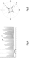
- Fig. 4 shows a diagram similar to that of Fig.3B in a real situation and for a time interval during which the blade holder 15 performs a plurality of rotations.
- the intensity of the signal S is shown on the y-axis and the number of revolutions (n) of the blade holder 15 is shown on the x-axis.
- the number of peaks Sp for each revolution is equal to the number of perforating blades 19 provided on the blade-holder 15. In this example the number is 4.
- the diagram of Fig.5 is a polar diagram showing the signal generated by the vibration sensor 31 on 360° rotation. At every revolution, if there are no alteration factors, such as for example damages to a perforating blade 19, the signal S of the diagram of Fig. 5 is repeated approximately equal to itself, i.e. for each revolution of the blade holder the signal S approximately overlaps to the previous signal.
- the signal S generated by the vibration sensor 31 can be used for one or more of the following purposes or functions.
- the signal peaks Sp can be used to properly adjust the position of the individual perforating blades 19, so that each of them has approximately the same degree of interference with the anvil blade 21. In fact, the greater the degree of interference between the perforating blade 19 and anvil blade 21, the greater the intensity of the signal peak Sp. If the perforating blades 19 are properly adjusted, so as to have all about the same degree of interference with the anvil blade 21, the peaks Sp generated in a complete rotation of the blade-holder 15 are approximately the same.
- the absolute value of the peak Sp is indicative of the interference between the perforating blade 19 and the anvil blade. It is possible to experimentally identify optimal peak values Sp, corresponding to optimal degrees of interference between each perforating blade 19 and the anvil blade 21. It is therefore possible to proceed for example in the following manner. Once the positions of the individual perforating blades 19 on the blade-holder 15 have been adjusted so that the peaks Sp are equal to one other, it is possible to adjust the mutual position between anvil blade 21 and blade-holder 15, until the correct mutual interference is achieved.
- any increase or decrease in all peak values Sp may be indicative of an alteration or drift of the mutual distance between the cutting edge of the anvil blade 21 and the cutting edges of the perforating blades 19.
- a decrease in the peak signal Sp can be indicative of wear of the perforating blades 19.
- minimum thresholds below which the replacement of the perforating blades 19 and/or of the anvil blade 21 can be required.
- a variation of one or more of the peaks Sp with respect to the others may be indicative of an alteration of the position of a single or of some perforating blades 19, or of excessive wear of a single or of some perforating blades 19.
- minimum thresholds can be used to signal the need for replacement of one or more perforating blades 19.
- Any anomalies of the intermediate signal between consecutive Sp peaks can be indicative of a localized damage of the respective perforating blade 19.
- the breaking of a piece of the cutting edge of a perforating blade 19 can generate, in the signal between two consecutive Sp peaks, anomalous intermediate peaks interspersed with areas without vibrations. This may be indicative of the fact that a piece of the edge of the respective perforating blade 19 has detached. If the anomaly is the same in all the intervals between the four peaks Sp, this can be indicative of damage to the anvil blade 21.
- the information contained in the signal S of the vibration sensor 31 can be used to detect other anomalies, for example an abnormal increase of the interference on all the perforating blades 19 (increase of all peak signals Sp). This can be indicative, for example of overheating of the perforating device 3 or of some parts thereof, with consequent abnormal thermal expansion, for example an expansion of the blade-holder 15. This situation can cause a detectable increase of all the peaks of the signal S.
- the signal S of the vibration sensor can also be used to perform a continuous adjustment of the perforating device 3, by means of an adjustment loop.
- maximum and minimum thresholds of the signal peaks Sp it is possible, for example, to move the position of the anvil blade 21 and/or of the axis A-A of the blade holder 15 in an automatic way, by means of support slides and numerically controlled servo-motors.
- the previous description refers to a system comprising a vibration sensor adapted to detect the mechanical vibration of the support structure 17.
- This embodiment can be particularly advantageous and beneficial in terms of reliability and/or simplicity.
- Figs. 6 to 9 show an embodiment, wherein a sensor adapted to detect an electrical parameter is used, for example a voltage, indicative of the mutual interaction between rotating perforating blades 19 and fixed anvil blade 21; 21B; 21C. 21B; 21C.
- an electrical parameter for example a voltage
- Fig. 6 schematically illustrates the perforating device 3 in an embodiment of this type.
- the same reference numbers indicate equal or corresponding parts to those described with reference to the embodiment describe above.
- Fig.6 schematically indicates a sensor 104 adapted to detect an electrical parameter, for example a voltage.
- the sensor 104 is connected to the system comprising the rotating blade-holder with the perforating blades 19 and the fixed anvil blade 21; 21B; 21C so as to be able to detect a voltage between the anvil blade 21 (or 21B, 21C, depending on which of the anvil blades operating) and the rotating perforating blades 19.
- an electrical parameter for example a voltage
- the sensor 104 is inserted in a measurement circuit 101, which comprises a voltage source 103, for example a direct voltage source, preferably a low voltage.
- the voltage of the source 103 is 24 Volts.
- the sensor 104 is functionally connected to the electronic control unit 33 and provides a voltage signal.
- the voltage detected by the sensor 101 is approximately equal to the voltage of the source 103 when there is no contact between the rotating perforating blades 19 and the anvil blade 21, while it is substantially lower, when the measurement circuit where the anvil blade 21 and the rotating perforating blades 19 are inserted, is closed, i.e. when there is a contact between anvil blade 21 and at least one of the rotating perforating blades 19.
- Fig. 7 schematically shows the voltage signal generated by the sensor 104 in the case in which the perforating device 3 is set so that there is no continuous contact between rotating perforating blades 19 and fixed anvil blade 21.
- This situation can occur, for example, if there are only one or two rotating perforating blades 19, so that for each complete rotation of the blade-holder 15 there are one or two time intervals in which there is no mutual contact between the rotating perforating blades 19 and the anvil blade 21.
- Fig.7 shows a condition of proper functioning.
- the voltage signal is deformed and has voltage peaks in the range (t2-t3) as shown schematically in Fig.7 .
- the electronic control unit 33 can detect this anomaly and trigger an alarm or provide a notification.
- the voltage signal is substantially continuous and low.
- Operating anomalies due for example to areas lacking the cutting edges of blades and/or of the anvil blade, cause a temporary opening of the measurement circuit and therefore voltage peaks, as shown schematically in the diagram of Fig. 10 , where the time is still in abscissa and the signal generated by the sensor in ordinate.
- a linear load cell or a matrix of load cells, or in general one or more load sensors, under the fixed anvil blade, or each anvil blade 21, 21B, 21C, to detect the load generated during the perforation, caused by the mutual interaction with the rotating perforating blades 19. It is also possible, in general, to arrange the load cells in combination with the rotating perforating blades 19, but this is less advantageous in that it requires a greater number of load sensors and also requires that the signal generated by the load sensors is transferred from the rotating blade holder 15 to the fixed electronic control unit 33.
- Fig. 11 shows load sensors, for example load cells 105 associated with each fixed anvil blade 21; 21B; 21C.
- the sensors 105 interface with the electronic control unit 33.
- the remaining components, substantially the same or equivalent to those already described, are indicated with the same reference numbers.
- irregularities in the signal read by the load cell 105 is indicative of a perforation performed incorrectly or even of the failure to perform the perforation.
- irregularities in the signal read by the load cell 105 is indicative of a perforation performed incorrectly or even of the failure to perform the perforation.
- Fig.12 illustrates a simplified and illustrative diagram showing the signal of the load sensor in ordinates as a function of time (in abscissae).
- the value S of the signal is indicative of the interference between rotating perforating blades and anvil blade and can be adjusted so as to bring it to the required value, by increasing or reducing the distance between blade holder 15 and beam 22.
- the signal of Fig. 12 is generated in the case of continuous contact between perforating blades 19 and anvil blade 21. The points where the signal drops abruptly are indicative of a malfunction, for example of broken sections of the cutting edges of blades 19 and anvil blade 21.
- a sound signal can be used as a parameter indicating the mutual co-action or interaction between rotating perforating blades 19 and anvil blade 21; 21B; 21C.
- This sound signal can be detected with one or more sensors, for example microphones, one of which is schematically indicated in broken lines with 107 in Fig.11 , interfaced with the electronic control unit 33.
- sensors for example microphones, one of which is schematically indicated in broken lines with 107 in Fig.11 , interfaced with the electronic control unit 33.
- the perforation is not constant, for example because a breakage happened in one or more of the rotating perforating blades 19 and/or in the anvil blade 21.
- problems similar to those encountered in perforating devices can also occur in cutting devices which divide a web material into separate sheets, for example a single-ply or multi-ply tissue paper in single sheets which can be folded and stacked.
- a non-limiting example of machines using such cutting devices are the so-called interfolding machines, which cut one or two webs of cellulosic material to form packs of interleaved sheets.
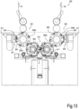
- FIG. 13 shows a front view of an interfolding machine comprising two cutting devices according to the present invention.
- the interfolding machine 200 comprises a first feed path for a first continuous web material N1 of tissue paper and a second feed path for a second continuous web material N2 of tissue paper.
- a first cutting device 201 is arranged along the first path, the cutting device comprising a first rotating cutting roller 203 provided with angularly spaced rotating cutting blades 203A.
- the first rotating cutting roller 203 constitutes a blade holder of the cutting device 201.
- the rotating cutting blades 203A co-act with a first stationary anvil blade 204.
- the stationary anvil blade 204 has a helical shape, while the rotating cutting blades 203A have a straight shape, parallel to the axis of rotation of the blade-holder or rotating cutting roller 203.
- an opposite arrangement is not excluded, with a straight stationary anvil blade and helical rotating cutting blades.
- a second cutting device 202 is arranged along the second path, substantially mirroring the first cutting device 201.
- the second cutting device 202 comprises a rotating cutting roller 205, provided with angularly spaced blades 205A.
- the rotating cutting roller 205 constitutes a blade holder of the cutting device 202.
- the blades 205A co-act with a second stationary anvil blade 206.
- the first rotating blade holder or cutting roller 203 and the second rotating blade holder or rotating cutting roller 205 are equipped with suction ports or other retaining means, to retain on the surface of the respective cutting rollers 3, 5 the sheets obtained by cutting the first and second continuous web material N1, N2, and transferring said sheets from the cutting rolls 203, 205 to interfolding rollers 209, 211.
- Said interfolding rollers 209, 211 rotate around rotation axes thereof parallel to each other and parallel to the rotation axes of the cutting rolls 203, 205.
- the two interfolding rollers 209, 211 form an interfolding nip 213.
- the interfolding rollers 209, 211 fold and interfold the sheets coming from the cutting devices 201, 202 to form a stack of sheets P.
- Each continuous web material N1, N2 is guided around the respective rotating cutting roller 203, 205 and is fed between the rotating cutting roller or blade-holder 203, 205 and the stationary anvil blade 204, 206.
- the co-action of the rotating cutting blades 203A with the stationary anvil blade 204 cuts the continuous web material N1 into individual sheets, which are then transferred from the first rotating cutting roller or blade-holder 203 to the first interfolding roller 209.
- the continuous web material N2 is guided around the second rotating cutting roller or blade holder 205 and cut into sheets by co-acting with the rotating cutting blades 205A with the stationary anvil blade 206.
- the individual sheets are then transferred from the second rotating cutting roller or blade-holder 205 to the second interfolding roller 211.
- the interfolding machine 200 briefly described above is known. There are other types of interfolding machines which provide only one feed path for a single web material, and which are always provided with at least one cutting device.
- the cutting device can be associated with a sensor adapted to detect a parameter indicative of a mutual interaction between the respective group of rotating blades and the respective anvil blade.
- a sensor associated with the first cutting device 201 is schematically indicated with 231
- a sensor associated with the second cutting device 202 is schematically indicated with 232.
- Each sensor 231, 232 can be made in any of the above ways described.
- the two sensors 231 and 232 are preferably equal to each other, but it is also possible to use different sensors for the two cutting devices 201, 202.
- the sensors 231, 232 can for example be mounted on, or associated with, a support structure 217 on which the rotating cutting rollers 203, 205 and the respective anvil blades are mounted.
- Each sensor 231, 232 can provide a central control unit (not shown) with a signal containing information on the proper operation of the respective cutting device 201, 202, in a manner substantially similar to that described with reference to the perforating device of the previously illustrated embodiments.
- the various sensors described above can be used together, instead of alternatively, exploiting in combination the different information they generate.
- a vibration sensor with a voltage sensor, to analyze the signal provided by the vibration sensor ( Figs.3A, 3B , 4, 5 ) only or mainly when the signal provided by the voltage sensor ( Figs 6 , 7 , 8 , 9 , 10 , 12 ) indicates the presence of a contact between the blades and the anvil blade.
- the vibration signal it is possible to determine the "quality" of the mutual co-action of blades and anvil blade.
- an excessive vibration indicates a too strong interference; on the contrary, a decrease in intensity of the vibration signal means a gradual wearing-out of the blades, which can be balanced by an equally gradual movement of the blades and the anvil blade towards each other.
- An anomalous discontinuity in the voltage signal means that at some point there is no contact because of a broken blade. Therefore it is possible to generate an alarm or to stop the device.
- the sound sensor can be used alternatively to, or in combination with a vibration sensor for detecting the vibrations of the mechanical structure and/or in combination with a voltage sensor ( Fig.6 ).
- Load cells detecting the stresses on the blades and/or on the anvil blade can also be used, as shown in Fig. 11 , in combination with one or more of the voltage, sound and vibration sensors.
- a signal of mutual interaction between the blades and the anvil blade by means of a pair of load cells applied to the beam 22, on opposite sides with respect to the web material feed path, or applied to the rotating blade-holder 15, 15B.
- the two load cells detect a load that varies due to the movement of the contact point between the fixed anvil blade 21 and the rotating blades 19, resulting from scissor-like cutting or perforation. Consequently, the signal detected by a load cell varies in opposite way with respect to the signal detected by the opposite load cell. While one signal increases from a minimum value to a maximum value, the other signal decreases from a maximum value to a minimum value
- Fig. 14 schematically shows an axonometric view of an arrangement similar to that of Fig.6 .
- Equal numbers indicate equal or equivalent parts.
- the beam 22, which holds the fixed anvil blades 21, 21A, 21B, is pressed by an actuator, not shown, against one or another of a plurality of pairs of abutments.
- Each pair of abutments comprises an abutment on one end and an abutment on the opposite end of beam 22.
- the beam is pressed against one or the other of the pairs of abutments, depending on which anvil blade shall start working.
- a load cell is associated with each abutment. Pairs of load cells associated with two separate abutments are indicated with 101, 104 and 102, 105. In the arrangement of Fig.14 the load cells 101, 104 are operative, associated with the abutments against which the beam 22 is pressed.
- Fig. 15 shows the pattern of the force detected by each of the two load cells as a function of the angle of rotation of the working rotating blade-holder 19 (or 19A).
- One force gradually increases and the other gradually decreases, since the two stresses on the two load cells at the opposite ends of the beam 22 vary as the point of contact between blade and anvil blade moves towards or away.
- the pattern of the two signals is repeated for each of the rotating blades 19 that starts working.
- one of the two load cells detects an increasing load while the other is gradually unloaded. In theory, therefore, at the middle of the cut the load of the two load cells must be the same.
- the lack of contact between blade and anvil blade, or an insufficient or excessive interference between blade and anvil blade results in an altered signal, which is indicative of malfunctions or worn blades.
- an unbalance of the two load signals is a symptom of incorrect positioning of the blade and anvil blade, which requires adjustment to reduce the distance between the blade and anvil blade on one side and to increase this distance on the opposite side.
- load cells can also be arranged on corresponding stop surfaces integral with the support structure, indicated with 103 in Fig. 14 .
- sensors can also be provided on the axis of the rotating blade-holders 15, 15A. These sensors can be applied, for example, to the support bearings of the blade-holders 15, 15B.
- sensors associated with the rotating blade holders or with the fixed beam 22 adapted to measure a force lying on a plane orthogonal to the axis of the rotating blade-holders 15, 15A, in horizontal direction, so as to measure the reaction forces due to the interactions of the rotating blades 19, 19B with the fixed anvil blade 21.
- Figs. 16A and 16B schematically show an end 22X of the fixed beam 22, to which a load cell 121 and an adjustable stop 123 are associated. A similar arrangement can be provided at the opposite end.
- This sensors configuration allows detecting a force that is independent of the pressure with which the fixed beam 22 carrying the anvil blades 21, 21A, 21B is pressed against the respective abutments 101, 104, 102, 105 ( Fig. 14 ).
- aforementioned configurations can also be provided in a cutting device, such as that of Fig. 13 , rather than in a perforating device.
- a perforating device for a final control of the perforation quality it is possible to use a high-speed camera, or a series of high-speed cameras adjacent to one another.
- the camera(s) detects the presence of perforations along the whole transverse length of the web material exiting from the perforating device. It is possible to detect all the perforations made by each blade or a subset of perforations made by some blades or by each blade, for example detecting a perforation every N perforations, where N can be for example comprised between 3 and 20, preferably between 3 and 10.
- the reference number 141 schematically indicates a video camera arranged downstream of the nip between the beam 22 and the rotating blade holder 15.
- the signals generated by the sensors can be processed by a computer with an artificial intelligence software, which accordingly adjusts the device in order always to maintain the high quality of the cut and/or of the perforation, and also to increase the useful life of the blades and anvil blades, reducing the wear thereof and making it more uniform.
- the artificial intelligence software can have internal self-learning algorithms (machine-learning) for self-learning the correct operation of the machine and/or a neural network. In the first case the software will learn and therefore correlate the proper operation of the machine with the inputs coming from one or more sensors.
- the presence of the perforations detected by the camera, the correct voltage signal detected by the sensor 104 and the force signal detected by the load cells identify a correct perforation or cut.
- the signal detected by the sensor 104 is correct but the forces detected by the load cells are not balanced, i.e. they do not follow the correct time path due to the mutual interaction between blade and anvil blade, it means that it is necessary to move one end of the perforating device closer and/or to move the other end away.
- the signal detected by the sensor 104 is correct but the camera detects less marked perforations and/or the force detected by the load cells is decreasing, it means that the blades are wearing out and therefore it is necessary to bring the blade closer to the anvil blade.
Landscapes
- Life Sciences & Earth Sciences (AREA)
- Forests & Forestry (AREA)
- Engineering & Computer Science (AREA)
- Mechanical Engineering (AREA)
- Perforating, Stamping-Out Or Severing By Means Other Than Cutting (AREA)
- Crushing And Pulverization Processes (AREA)
Applications Claiming Priority (3)
| Application Number | Priority Date | Filing Date | Title |
|---|---|---|---|
| IT201800006343 | 2018-06-15 | ||
| EP19737904.3A EP3807063B1 (de) | 2018-06-15 | 2019-06-10 | Vorrichtung mit rotierenden klingen, maschine mit dieser vorrichtung und entsprechendes verfahren |
| PCT/IB2019/054813 WO2019239283A1 (en) | 2018-06-15 | 2019-06-10 | Device with rotating blades, machine comprising said device, and related method |
Related Parent Applications (2)
| Application Number | Title | Priority Date | Filing Date |
|---|---|---|---|
| EP19737904.3A Division-Into EP3807063B1 (de) | 2018-06-15 | 2019-06-10 | Vorrichtung mit rotierenden klingen, maschine mit dieser vorrichtung und entsprechendes verfahren |
| EP19737904.3A Division EP3807063B1 (de) | 2018-06-15 | 2019-06-10 | Vorrichtung mit rotierenden klingen, maschine mit dieser vorrichtung und entsprechendes verfahren |
Publications (2)
| Publication Number | Publication Date |
|---|---|
| EP4459519A2 true EP4459519A2 (de) | 2024-11-06 |
| EP4459519A3 EP4459519A3 (de) | 2025-01-08 |
Family
ID=63579646
Family Applications (2)
| Application Number | Title | Priority Date | Filing Date |
|---|---|---|---|
| EP24201176.5A Pending EP4459519A3 (de) | 2018-06-15 | 2019-06-10 | Vorrichtung mit rotierenden schaufeln, maschine mit dieser vorrichtung und zugehöriges verfahren |
| EP19737904.3A Active EP3807063B1 (de) | 2018-06-15 | 2019-06-10 | Vorrichtung mit rotierenden klingen, maschine mit dieser vorrichtung und entsprechendes verfahren |
Family Applications After (1)
| Application Number | Title | Priority Date | Filing Date |
|---|---|---|---|
| EP19737904.3A Active EP3807063B1 (de) | 2018-06-15 | 2019-06-10 | Vorrichtung mit rotierenden klingen, maschine mit dieser vorrichtung und entsprechendes verfahren |
Country Status (4)
| Country | Link |
|---|---|
| US (1) | US20210252728A1 (de) |
| EP (2) | EP4459519A3 (de) |
| CN (1) | CN112423951B (de) |
| WO (1) | WO2019239283A1 (de) |
Families Citing this family (9)
| Publication number | Priority date | Publication date | Assignee | Title |
|---|---|---|---|---|
| IT202100005600A1 (it) * | 2021-03-10 | 2022-09-10 | Paper Converting Machine Company S P A | Sistema di controllo del funzionamento di una macchina ribobinatrice |
| US12330329B2 (en) | 2021-03-30 | 2025-06-17 | Maxcess Americas, Inc. | Rotary die cutting device and method for setting a gap dimension of a gap between a die cutting cylinder and a counter pressure cylinder of the rotary die cutting device |
| IT202100022598A1 (it) | 2021-08-31 | 2023-03-03 | Koerber Tissue S P A | Un dispositivo a lame ruotanti, una macchina comprendente detto dispositivo, e metodo |
| CN113579363B (zh) * | 2021-09-01 | 2022-05-03 | 福建省闽铝轻量化汽车制造有限公司 | 一种多层腹板的加工方法及系统 |
| IT202200011492A1 (it) * | 2022-05-31 | 2023-12-01 | Valmet Tissue Converting S P A | Dispositivo supporto per una lama, dispositivo di taglio o perforazione comprendente il dispositivo di supporto e macchina |
| IT202200016767A1 (it) * | 2022-08-05 | 2024-02-05 | Ot Lucca S R L | Macchina interfogliatrice, impianto e metodo per il cambio cut-off |
| CN119894650A (zh) | 2022-09-13 | 2025-04-25 | 麦克氏国际公司 | 用于设定轴向位置和间隙尺寸的刻划装置及方法 |
| WO2024086032A1 (en) | 2022-10-19 | 2024-04-25 | Paper Converting Machine Company | Apparatus for forming stacks of interfolded sheets and comprising a fluid delivery system |
| IT202400001653A1 (it) | 2024-01-29 | 2025-07-29 | Valmet Tissue Converting S P A | Un dispositivo di perforazione o di taglio, una macchina comprendente detto dispositivo, e metodo |
Citations (8)
| Publication number | Priority date | Publication date | Assignee | Title |
|---|---|---|---|---|
| EP0454633A2 (de) | 1990-04-27 | 1991-10-30 | FABIO PERINI S.p.A. | Aufrollvorrichtung mit Mitteln zur Änderung der Anzahl von Perforationen um jede Rolle während der Herstellung |
| US5125302A (en) | 1989-02-07 | 1992-06-30 | Fabio Perini S.P.A. | Perforating apparatus for transverse perforations in webs of paper-like material |
| US5284304A (en) | 1991-04-03 | 1994-02-08 | Fabio Perini S.P.A. | Perforating apparatus for paper webs and the like, with reciprocating motion of translation of the counter-blade |
| EP0694020A1 (de) | 1993-03-24 | 1996-01-31 | Perini Fabio Spa | Wiederaufwickelvorrichtung und verfahren zum bilden von bahnmaterialrollen mit mitteln zum abtrennen der bahn |
| WO2000073029A1 (en) | 1999-05-28 | 2000-12-07 | Fabio Perini S.P.A. | Device with thermal system for controlling the interference between two members moving relative to each other |
| US6431491B1 (en) | 1998-07-27 | 2002-08-13 | Fabio Perini S.P.A. | Perforator for weblike materials with means for modifying the interval between consecutive lines of perforations |
| EP2621844A1 (de) | 2010-09-28 | 2013-08-07 | Fabio Perini S.p.A. | Aufwickler und verfahren zur herstellung von bahnmaterialrollen |
| EP2655227A1 (de) | 2010-12-22 | 2013-10-30 | Fabio Perini S.p.A. | Aufwickelmaschine und wickelverfahren |
Family Cites Families (11)
| Publication number | Priority date | Publication date | Assignee | Title |
|---|---|---|---|---|
| FI79256C (fi) * | 1987-12-09 | 1989-12-11 | Ahlstroem Valmet | Foerfarande och anordning foer reglering av skaerbettens bettmellanrum i en arkskaermaskin. |
| DE59310123D1 (de) * | 1992-03-24 | 2001-01-04 | Steinemann Ulrich Ag | Verfahren und Vorrichtung zur Trennung von kaschierten Laminaten |
| DE4336955A1 (de) * | 1992-05-02 | 1995-05-04 | Heidelberger Druckmasch Ag | Einrichtung zur Einstellung eines Schneidmessers zum Trennen von Materialbahnen |
| US6032558A (en) * | 1998-03-20 | 2000-03-07 | Marquip, Inc. | Rotary knife with active vibration control |
| US6698323B2 (en) * | 2000-05-09 | 2004-03-02 | Georgia-Pacific Corporation | Apparatus and method for detecting when a web is not being perforated |
| CN101015390A (zh) * | 2007-02-12 | 2007-08-15 | 山东中烟工业公司滕州卷烟厂 | 薄片断丝刀 |
| US20140331833A1 (en) * | 2013-05-13 | 2014-11-13 | Stephen F. Gass | Detection system for power equipment |
| EP3243614B1 (de) * | 2016-05-09 | 2019-10-09 | Sidel Participations | Schneideinheit für eine etikettiermaschine |
| CN106378802A (zh) * | 2016-12-05 | 2017-02-08 | 安徽睿知信信息科技有限公司 | 一种管道切割装置 |
| IT201700011567A1 (it) * | 2017-02-02 | 2018-08-02 | Futura Spa | procedimento ed apparecchiatura per il controllo della corretta esecuzione delle linee di pre-taglio. |
| CN106956307B (zh) * | 2017-04-11 | 2018-10-26 | 涿州皓原箔业有限公司 | 一种多机联动式切块断张机 |
-
2019
- 2019-06-10 WO PCT/IB2019/054813 patent/WO2019239283A1/en not_active Ceased
- 2019-06-10 EP EP24201176.5A patent/EP4459519A3/de active Pending
- 2019-06-10 CN CN201980046912.3A patent/CN112423951B/zh active Active
- 2019-06-10 EP EP19737904.3A patent/EP3807063B1/de active Active
- 2019-06-10 US US17/251,868 patent/US20210252728A1/en not_active Abandoned
Patent Citations (8)
| Publication number | Priority date | Publication date | Assignee | Title |
|---|---|---|---|---|
| US5125302A (en) | 1989-02-07 | 1992-06-30 | Fabio Perini S.P.A. | Perforating apparatus for transverse perforations in webs of paper-like material |
| EP0454633A2 (de) | 1990-04-27 | 1991-10-30 | FABIO PERINI S.p.A. | Aufrollvorrichtung mit Mitteln zur Änderung der Anzahl von Perforationen um jede Rolle während der Herstellung |
| US5284304A (en) | 1991-04-03 | 1994-02-08 | Fabio Perini S.P.A. | Perforating apparatus for paper webs and the like, with reciprocating motion of translation of the counter-blade |
| EP0694020A1 (de) | 1993-03-24 | 1996-01-31 | Perini Fabio Spa | Wiederaufwickelvorrichtung und verfahren zum bilden von bahnmaterialrollen mit mitteln zum abtrennen der bahn |
| US6431491B1 (en) | 1998-07-27 | 2002-08-13 | Fabio Perini S.P.A. | Perforator for weblike materials with means for modifying the interval between consecutive lines of perforations |
| WO2000073029A1 (en) | 1999-05-28 | 2000-12-07 | Fabio Perini S.P.A. | Device with thermal system for controlling the interference between two members moving relative to each other |
| EP2621844A1 (de) | 2010-09-28 | 2013-08-07 | Fabio Perini S.p.A. | Aufwickler und verfahren zur herstellung von bahnmaterialrollen |
| EP2655227A1 (de) | 2010-12-22 | 2013-10-30 | Fabio Perini S.p.A. | Aufwickelmaschine und wickelverfahren |
Also Published As
| Publication number | Publication date |
|---|---|
| EP3807063A1 (de) | 2021-04-21 |
| EP3807063B1 (de) | 2025-01-08 |
| BR112020025407A2 (pt) | 2021-03-09 |
| EP3807063C0 (de) | 2025-01-08 |
| CN112423951B (zh) | 2022-06-07 |
| US20210252728A1 (en) | 2021-08-19 |
| WO2019239283A1 (en) | 2019-12-19 |
| EP4459519A3 (de) | 2025-01-08 |
| CN112423951A (zh) | 2021-02-26 |
Similar Documents
| Publication | Publication Date | Title |
|---|---|---|
| EP3807063B1 (de) | Vorrichtung mit rotierenden klingen, maschine mit dieser vorrichtung und entsprechendes verfahren | |
| US3744361A (en) | Process and apparatus for cutting elongated material | |
| US20240109744A1 (en) | Device with rotating blades, machine comprising said device, and related method | |
| CN109746960B (zh) | 用于将片材转换成连续条带的设备和方法 | |
| RU2753718C2 (ru) | Способ управления устройством для предварительного надрезания и перемоточная машина | |
| EP3997534B1 (de) | Verfahren zur überwachung einer anlage zur herstellung von wellpappe | |
| JPH05278925A (ja) | ウエブ材料を切断する方法および装置 | |
| US20240359354A1 (en) | A rotating blade device, a machine comprising said device, and method | |
| EP1919812B1 (de) | Wicklerbahntrenner mit früherfassung und bahnumleitung zur beseitigung von ausrüstungsbeschädigung | |
| BR112020025407B1 (pt) | Dispositivo com lâminas rotativas para processamento de um material de tela e método de processamento de um material de tela contínua | |
| WO1999057050A1 (en) | Cross-cutting apparatus and method for a web-like material, as well as sheet cutter | |
| EP3243614B1 (de) | Schneideinheit für eine etikettiermaschine | |
| CN113226676B (zh) | 穿孔装置以及包括所述穿孔装置的转换机器 | |
| JP2011140401A (ja) | チョッパ折り装置を制御する方法及びチョッパ折り装置 | |
| EP4003889B1 (de) | Verfahren zum aufwickeln einer vliesstoffbahn aus mineralwolle und vorrichtung zur durchführung des verfahrens | |
| EP1660398B1 (de) | Verfahren und vorrichtung zum trennen von bahnmaterial | |
| US20250345963A1 (en) | Perforating unit for weblike materials | |
| IT202400001653A1 (it) | Un dispositivo di perforazione o di taglio, una macchina comprendente detto dispositivo, e metodo | |
| BR112021012400A2 (pt) | Método para cortar através de uma tela de material movendo em uma direção de movimento e também um dispositivo para esse propósito | |
| WO2024263851A1 (en) | Perforator unit and indexer for perforator unit | |
| GB1163453A (en) | Apparatus for Controlling the Position of Transverse Perforated Folding Lines in Webs in Printing Presses or Paper-Processing Machines | |
| EP3272688B1 (de) | Locherbaugruppe für umwickler von blattmaterial |
Legal Events
| Date | Code | Title | Description |
|---|---|---|---|
| PUAI | Public reference made under article 153(3) epc to a published international application that has entered the european phase |
Free format text: ORIGINAL CODE: 0009012 |
|
| STAA | Information on the status of an ep patent application or granted ep patent |
Free format text: STATUS: THE APPLICATION HAS BEEN PUBLISHED |
|
| AC | Divisional application: reference to earlier application |
Ref document number: 3807063 Country of ref document: EP Kind code of ref document: P |
|
| AK | Designated contracting states |
Kind code of ref document: A2 Designated state(s): AL AT BE BG CH CY CZ DE DK EE ES FI FR GB GR HR HU IE IS IT LI LT LU LV MC MK MT NL NO PL PT RO RS SE SI SK SM TR |
|
| REG | Reference to a national code |
Ref country code: DE Ref legal event code: R079 Free format text: PREVIOUS MAIN CLASS: G06N0020000000 Ipc: B26D0001380000 |
|
| PUAL | Search report despatched |
Free format text: ORIGINAL CODE: 0009013 |
|
| AK | Designated contracting states |
Kind code of ref document: A3 Designated state(s): AL AT BE BG CH CY CZ DE DK EE ES FI FR GB GR HR HU IE IS IT LI LT LU LV MC MK MT NL NO PL PT RO RS SE SI SK SM TR |
|
| RIC1 | Information provided on ipc code assigned before grant |
Ipc: G06N 3/02 20060101ALI20241204BHEP Ipc: B65H 45/24 20060101ALI20241204BHEP Ipc: G06N 20/00 20190101ALI20241204BHEP Ipc: B26D 1/00 20060101ALI20241204BHEP Ipc: B26F 1/38 20060101ALI20241204BHEP Ipc: B26F 1/20 20060101ALI20241204BHEP Ipc: B26D 5/00 20060101ALI20241204BHEP Ipc: B26D 1/40 20060101ALI20241204BHEP Ipc: B26D 1/38 20060101AFI20241204BHEP |
|
| STAA | Information on the status of an ep patent application or granted ep patent |
Free format text: STATUS: REQUEST FOR EXAMINATION WAS MADE |
|
| 17P | Request for examination filed |
Effective date: 20250703 |
|
| GRAP | Despatch of communication of intention to grant a patent |
Free format text: ORIGINAL CODE: EPIDOSNIGR1 |
|
| STAA | Information on the status of an ep patent application or granted ep patent |
Free format text: STATUS: GRANT OF PATENT IS INTENDED |