EP4458620A2 - Alarmvorrichtung für sitzmissbrauch - Google Patents
Alarmvorrichtung für sitzmissbrauch Download PDFInfo
- Publication number
- EP4458620A2 EP4458620A2 EP24194651.6A EP24194651A EP4458620A2 EP 4458620 A2 EP4458620 A2 EP 4458620A2 EP 24194651 A EP24194651 A EP 24194651A EP 4458620 A2 EP4458620 A2 EP 4458620A2
- Authority
- EP
- European Patent Office
- Prior art keywords
- seat
- alarm
- headrest
- switch
- base
- Prior art date
- Legal status (The legal status is an assumption and is not a legal conclusion. Google has not performed a legal analysis and makes no representation as to the accuracy of the status listed.)
- Pending
Links
Images


Classifications
-
- B—PERFORMING OPERATIONS; TRANSPORTING
- B60—VEHICLES IN GENERAL
- B60R—VEHICLES, VEHICLE FITTINGS, OR VEHICLE PARTS, NOT OTHERWISE PROVIDED FOR
- B60R21/00—Arrangements or fittings on vehicles for protecting or preventing injuries to occupants or pedestrians in case of accidents or other traffic risks
- B60R21/01—Electrical circuits for triggering passive safety arrangements, e.g. airbags, safety belt tighteners, in case of vehicle accidents or impending vehicle accidents
- B60R21/015—Electrical circuits for triggering passive safety arrangements, e.g. airbags, safety belt tighteners, in case of vehicle accidents or impending vehicle accidents including means for detecting the presence or position of passengers, passenger seats or child seats, and the related safety parameters therefor, e.g. speed or timing of airbag inflation in relation to occupant position or seat belt use
- B60R21/01554—Seat position sensors
-
- B—PERFORMING OPERATIONS; TRANSPORTING
- B60—VEHICLES IN GENERAL
- B60N—SEATS SPECIALLY ADAPTED FOR VEHICLES; VEHICLE PASSENGER ACCOMMODATION NOT OTHERWISE PROVIDED FOR
- B60N2/00—Seats specially adapted for vehicles; Arrangement or mounting of seats in vehicles
- B60N2/02—Seats specially adapted for vehicles; Arrangement or mounting of seats in vehicles the seat or part thereof being movable, e.g. adjustable
- B60N2/0224—Non-manual adjustments, e.g. with electrical operation
- B60N2/0244—Non-manual adjustments, e.g. with electrical operation with logic circuits
- B60N2/0272—Non-manual adjustments, e.g. with electrical operation with logic circuits using sensors or detectors for detecting the position of seat parts
-
- B—PERFORMING OPERATIONS; TRANSPORTING
- B60—VEHICLES IN GENERAL
- B60N—SEATS SPECIALLY ADAPTED FOR VEHICLES; VEHICLE PASSENGER ACCOMMODATION NOT OTHERWISE PROVIDED FOR
- B60N2/00—Seats specially adapted for vehicles; Arrangement or mounting of seats in vehicles
- B60N2/24—Seats specially adapted for vehicles; Arrangement or mounting of seats in vehicles for particular purposes or particular vehicles
- B60N2/26—Seats specially adapted for vehicles; Arrangement or mounting of seats in vehicles for particular purposes or particular vehicles for children
- B60N2/28—Seats readily mountable on, and dismountable from, existing seats or other parts of the vehicle
- B60N2/2821—Seats readily mountable on, and dismountable from, existing seats or other parts of the vehicle having a seat and a base part
-
- B—PERFORMING OPERATIONS; TRANSPORTING
- B60—VEHICLES IN GENERAL
- B60N—SEATS SPECIALLY ADAPTED FOR VEHICLES; VEHICLE PASSENGER ACCOMMODATION NOT OTHERWISE PROVIDED FOR
- B60N2/00—Seats specially adapted for vehicles; Arrangement or mounting of seats in vehicles
- B60N2/24—Seats specially adapted for vehicles; Arrangement or mounting of seats in vehicles for particular purposes or particular vehicles
- B60N2/26—Seats specially adapted for vehicles; Arrangement or mounting of seats in vehicles for particular purposes or particular vehicles for children
- B60N2/28—Seats readily mountable on, and dismountable from, existing seats or other parts of the vehicle
- B60N2/2851—Seats readily mountable on, and dismountable from, existing seats or other parts of the vehicle provided with head-rests
-
- B—PERFORMING OPERATIONS; TRANSPORTING
- B60—VEHICLES IN GENERAL
- B60N—SEATS SPECIALLY ADAPTED FOR VEHICLES; VEHICLE PASSENGER ACCOMMODATION NOT OTHERWISE PROVIDED FOR
- B60N2/00—Seats specially adapted for vehicles; Arrangement or mounting of seats in vehicles
- B60N2/24—Seats specially adapted for vehicles; Arrangement or mounting of seats in vehicles for particular purposes or particular vehicles
- B60N2/26—Seats specially adapted for vehicles; Arrangement or mounting of seats in vehicles for particular purposes or particular vehicles for children
- B60N2/28—Seats readily mountable on, and dismountable from, existing seats or other parts of the vehicle
- B60N2/2869—Seats readily mountable on, and dismountable from, existing seats or other parts of the vehicle rotatable about a vertical axis
-
- B—PERFORMING OPERATIONS; TRANSPORTING
- B60—VEHICLES IN GENERAL
- B60N—SEATS SPECIALLY ADAPTED FOR VEHICLES; VEHICLE PASSENGER ACCOMMODATION NOT OTHERWISE PROVIDED FOR
- B60N2/00—Seats specially adapted for vehicles; Arrangement or mounting of seats in vehicles
- B60N2/24—Seats specially adapted for vehicles; Arrangement or mounting of seats in vehicles for particular purposes or particular vehicles
- B60N2/26—Seats specially adapted for vehicles; Arrangement or mounting of seats in vehicles for particular purposes or particular vehicles for children
- B60N2/28—Seats readily mountable on, and dismountable from, existing seats or other parts of the vehicle
- B60N2/2887—Fixation to a transversal anchorage bar, e.g. isofix
-
- B—PERFORMING OPERATIONS; TRANSPORTING
- B60—VEHICLES IN GENERAL
- B60N—SEATS SPECIALLY ADAPTED FOR VEHICLES; VEHICLE PASSENGER ACCOMMODATION NOT OTHERWISE PROVIDED FOR
- B60N2/00—Seats specially adapted for vehicles; Arrangement or mounting of seats in vehicles
- B60N2/80—Head-rests
- B60N2/806—Head-rests movable or adjustable
- B60N2/809—Head-rests movable or adjustable vertically slidable
-
- G—PHYSICS
- G08—SIGNALLING
- G08B—SIGNALLING SYSTEMS, e.g. PERSONAL CALLING SYSTEMS; ORDER TELEGRAPHS; ALARM SYSTEMS
- G08B21/00—Alarms responsive to a single specified undesired or abnormal condition and not otherwise provided for
- G08B21/18—Status alarms
- G08B21/24—Reminder alarms, e.g. anti-loss alarms
Definitions
- the present invention relates to a seat misuse alarm device according to the precharacterizing clause of claim 1.
- a child safety seat is designed for ensuring safety of a child in a car.
- the child safety seat is assembled in the car to allow the child sitting thereon for constraining the child in the car, so as to ensure safety of the child.
- a conventional child safety seat usually includes a base and a seat rotatably disposed on the base. The seat has a forward facing position and a rearward facing position relative to the base, so that a user can adjust the seat to a desired position according to the practical needs. For safety issues, it is forbidden that the user adjusts the seat to the forward facing position and then put a child from 0 to 15 months on the seat. However, since the child safety seat does not have a seat misuse alarm function, the user often puts a child from 0 to 15 months on the seat at the forward facing position by mistake. Thus, it may cause a great risk to safety of a child in a car.
- the present invention aims at providing a seat misuse alarm device for sending out an alarm when a seat is misused.
- the claimed seat misuse alarm device of the present invention includes a base, a seat, an alarm mechanism, and a switch triggering device.
- the seat has a forward facing position and a rearward facing position relative the base.
- the alarm mechanism has a switch.
- the switch triggering device triggers the switch to close for making the alarm mechanism send out an alarm when the seat is located at the forward facing position relative to the base.
- the seat is rotatably connected to the base.
- the alarm mechanism is disposed on one of the base and the seat, and the switch triggering device is disposed on the other of the base and the seat.
- the alarm mechanism is disposed on the base, and the switch triggering device is disposed on the seat.
- a first hole is formed at a side of the base, the switch is located in the first hole, a second hole is formed at a side of the seat, the switch triggering device is disposed through the second hole, and with rotation of the seat to the forward facing position relative to the base, the first hole is aligned with the second hole to make an end of the switch triggering device extend into the first hole and then trigger the switch to close.
- the switch triggering device includes a driving member and an elastic returning member, the driving member is slidably disposed in the second hole, and the elastic returning member is disposed between the driving member and the seat for providing an elastic force to make the driving member ejected from the second hole.
- a first limiting portion is formed on an inner wall of the second hole, a protrusion is formed on the driving member, and the elastic returning member is disposed between the first limiting portion and the protrusion.
- a fixing base is fixed to the inner wall of the second hole, and the first limiting portion protrudes from the fixing base.
- a second limiting portion is formed on the fixing base and is spaced apart from the first limiting portion, and the protrusion is located between the first limiting portion and the second limiting portion.
- the elastic returning member jackets the driving member.
- the alarm mechanism includes a control device and an alarm device, the switch, the control device, and the alarm device are electrically connected to each other and cooperatively form an alarm circuit, and when the switch is triggered to close, the control device controls the alarm device to send out the alarm.
- the control device controls the alarm device to stop sending out the alarm.
- the seat misuse alarm device further includes a headrest mechanism.
- the headrest mechanism is movably disposed on the seat and electrically connected to the alarm mechanism.
- a height of the headrest mechanism relative to the seat determines whether to conduct the alarm mechanism for making the alarm mechanism selectively send out the alarm.
- the headrest mechanism includes a headrest, a headrest fixing base, and a headrest triggering switch
- the headrest is slidably disposed on a front side of the seat to be slidable between a higher position and a lower position relative to the seat
- the headrest passes through the seat to be connected to the headrest fixing base located on a back side of the seat for making the headrest fixing base slidable together with the headrest
- the headrest triggering switch is disposed on the back side of the seat and is electrically connected to the alarm mechanism
- the alarm mechanism sends out the alarm when the headrest slides to the lower position relative to the seat to make the headrest fixing base trigger the headrest triggering switch to close and the seat is located at the forward facing position relative to the base to trigger the switch to close.
- the headrest fixing base has a driving rib protruding therefrom corresponding to the headrest triggering switch, and the driving rib presses the headrest triggering switch to close when the headrest slides to the lower position relative to the seat.
- the alarm device does not send out the alarm.
- the headrest mechanism includes a headrest, the headrest is slidably disposed on a front side of the seat to be slidable between a higher position and a lower position, the headrest is electrically connected to the alarm mechanism for cooperatively forming an alarm circuit, and the headrest breaks the alarm circuit to make the alarm device not send out the alarm when the headrest slides to the higher position relative to the seat.
- the present invention adopts the design that the switch triggering device is aligned with the switch of the alarm mechanism for triggering the switch to close when the seat is located at the forward facing position relative to the base.
- the alarm mechanism can send out an alarm to remind a user not to put a child from 0 to 15 months on the seat at the forward facing position.
- the present invention can improve operational safety in use of a child safety seat.
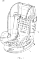
- a seat misuse alarm device 100 of the present invention includes a base 1, a seat 2, an alarm mechanism 3, and a switch triggering device 4.
- the seat 2 has a forward facing position and a rearward facing position relative to the base 1.
- the seat 2 is rotatably connected to the base 1.
- the seat 2 can be adjusted to the forward facing position or the rearward facing position via rotation of the seat 2 relative to the base 1, but the present invention is not limited thereto.
- the seat 2 could be detachably connected to the base 1. In such a manner, the seat 2 could be detached from the base 1, moved to the forward facing position or the rearward facing position, and then reassembled with the base 1.
- the alarm mechanism 3 is disposed on one of the base 1 and the seat 2, and the switch triggering device 4 is disposed on the other of the base 1 and the seat 2.
- the alarm mechanism 3 has a switch 31.
- the switch triggering device 4 triggers the switch 31 to close, so as to make the alarm mechanism 3 send out an alarm.
- the alarm mechanism 3 is disposed on the base 1, and the switch triggering device 4 is disposed on the seat 2.
- the switch triggering device 4 With rotation of the seat 2 to the forward facing position relative to the base 1, the switch triggering device 4 rotates to be aligned with the switch 31 of the alarm mechanism 3 and then trigger the switch 31 to close for making the alarm mechanism 3 send out the alarm, so as to remind a user not to put a child from 0 to 15 months on the seat 2 located at the forward facing position.
- the alarm mechanism 3 could be disposed on the seat 2 and the switch triggering device 4 could be disposed on the base 1 for achieving the same alarm effect.
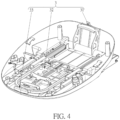
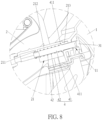
- a first hole 11 is formed at a side of the base 1, and the switch 31 is disposed in the first hole 11.
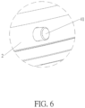
- a second hole 21 is formed at a side of the seat 2, and the switch triggering device 4 is disposed through the second hole 21. With rotation of the seat 2 to the forward facing position relative to the base 1, the first hole 11 is aligned with the second hole 21 to make an end of the switch triggering device 4 extend into the first hole 11 and then trigger the switch 31 to close.
- the switch triggering device 4 includes a driving member 41 and an elastic returning member 42.
- the driving member 41 is slidably disposed in the second hole 21.
- the elastic returning member 42 is disposed between the driving member 41 and the seat 2 for providing an elastic force to make the driving member 41 ejected out of the second hole 21.
- the elastic returning member 42 could be a conventional compression spring commonly seen in the prior art.
- the switch triggering device 4 is not limited to the aforesaid embodiment, meaning that the present invention could adopt the design that the switch triggering device is an elastic deformable member in another embodiment.
- a first limiting portion 211 is formed on an inner wall of the second hole 21, and a protrusion 411 is formed on the driving member 41.
- the protrusion 411 is formed on a middle portion of the driving member 41, and the elastic returning member 42 is disposed between the first limiting portion 211 and the protrusion 411.
- a fixing base 212 is fixed to the inner wall of the second hole 21, and the first limiting portion 211 protrudes from the fixing base 212, and the elastic returning member 42 jackets the driving member 41.
- the design of the first limiting portion 211 is not limited to the aforesaid embodiment.
- the present invention could adopt the design that the first limiting portion 211 directly protrudes from the inner wall of the second hole 21.
- a second limiting portion 213 protrudes from the fixing base 212 and is spaced apart from the first limiting portion 211, and the protrusion 411 is located between the first limiting portion 211 and the second limiting portion 213.
- the driving member 41 can be partially constrained in the second hole 21 by the second limiting portion 213 limiting the protrusion 411 of the driving member 41, so as to prevent complete ejection of the driving member 41 out of the second hole 21 via the elastic force provided by the elastic returning member 42.
- the alarm mechanism 3 includes a control device 32 and an alarm device 33.
- the switch 31, the control device 32, and the alarm device 33 are electrically connected to each other and cooperatively form an alarm circuit.
- the control device 32 controls the alarm device 33 to send out the alarm.
- the control device 32 is disposed in the base 1 and located at a middle portion of the base 1
- the alarm device 33 is located at an outer front end of the base 1
- the switch 31 is electrically connected to the control device 32 and the alarm device 33 via wires.
- a power source is disposed in the control device 32.
- the related description for the control device 32 and the alarm device 33 is omitted since it is commonly seen in the prior art.
- the control device 32 controls the alarm device 33 to stop sending out the alarm.
- the predetermined value could be set as two, three, or four seconds, but not limited thereto.
- the control device 32 controls the alarm device 33 to send out the alarm.
- the control device 32 controls the alarm device 33 to stop sending out the alarm until next time that the driving member 41 triggers the switch 31 again.
- the detailed description for the operations of the seat misuse alarm device 100 is provided as follows according to FIGS. 1-8 .
- the first hole 11 is misaligned with the second hole 21, and the side wall of the base 1 presses the driving member 41 into the second hole 21 to make the elastic returning member 42 compressed by the driving member 41.
- the switch 31 is in an open state, and the alarm device 33 does not send out the alarm.
- the control device 32 controls the alarm device 33 to send out the alarm for reminding the user not to put a child from 0 to 15 months on the seat 2 located at the forward facing position. After the alarm time of the alarm device 33 reaches to the predetermined value, the control device 32 controls the alarm device to stop sending out the alarm until next time that the driving member 41 triggers the switch 31 again.
- the present invention adopts the design that the alarm device 3 is disposed on one of the base 1 and the seat 2 and the switch triggering device 4 is disposed on the other of the base 1 and the seat 2.
- the switch triggering device 4 With rotation of the seat 2 to the forward facing position relative to the base 1, the switch triggering device 4 rotates to be aligned with the switch 31 of the alarm mechanism 3, and then triggers the switch 31 to close for making the alarm mechanism 3 send out the alarm, so as to remind the user not to put a child from 0 to 15 months on the seat 2 located at the forward facing position.
- the present invention improves operational safety in use of a child safety seat.
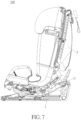
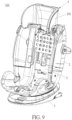
- FIG. 9 is a diagram of a headrest 101 of the seat misuse alarm device 100 sliding upward to a higher position.
- FIG. 10 is a diagram of the headrest 101 of the seat misuse alarm device 100 sliding downward to a lower position.
- FIG. 11 is a back view of the seat misuse alarm device 100 in FIG. 9 .
- the seat misuse alarm device 100 could further include a headrest mechanism 5.
- the headrest mechanism 5 is movably disposed on the seat 2 and electrically connected to the alarm mechanism 3.
- the headrest mechanism 5 could include the headrest 101, a headrest fixing base 102, and a headrest triggering switch 103, but the present invention is not limited thereto.
- the headrest 101 is slidably disposed on a front side F of the seat 2 to be slidable between the higher position as shown in FIG. 9 and the lower position as shown in FIG. 10 relative to the seat 2, but the present invention is not limited thereto.
- the headrest 101 passes through the seat 2 to be connected to the headrest fixing base 102 located at a back side B of the seat 2, so that the headrest fixing base 102 can slide together with the headrest 101 relative to the seat 2.
- the headrest triggering switch 103 is disposed on the back side B of the seat 2 and is electrically connected to the alarm mechanism 3.
- FIG. 12 which is a circuit diagram of the headrest triggering switch 103 in FIG. 11 , the switch 31, the control device 32, and the alarm device 33
- the headrest triggering switch 103 can form an alarm circuit 104 cooperatively with the switch 31, the control device 32, and the alarm device 33.
- FIG. 13 which is a diagram of the headrest fixing base 102 in FIG.
- the headrest fixing base 102 has a driving rib 105 protruding therefrom corresponding to the headrest triggering switch 103 for pressing the headrest triggering switch 103 to close, but the present invention is not limited thereto.
- the elastic returning member 42 drives the driving member 41 to be ejected out of the second hole 21 and then extend into the first hole 11 of the base 1 for triggering the switch 31 to close.
- the headrest fixing base 102 can slide synchronously to a position where the driving rib 105 presses the headrest triggering switch 103 to close (as shown in FIG.
- the alarm circuit 104 can be in a closed state such that the control device 32 can control the alarm device 33 to send out the alarm (e.g. light or sound). Accordingly, the seat misuse alarm device 100 can more precisely remind a user not to put a child from 0 to 15 months on the seat 2 located at the forward facing position.
- the alarm circuit 104 is in an open state since the headrest fixing base 102 is away from the headrest triggering switch 103 and fails to trigger the headrest triggering switch 103 to close. Therefore, the alarm device 33 does not send out the alarm.
- the present invention could adopt the circuit breaking design.
- the headrest mechanism 5 could only include the headrest 101.
- the headrest 101 is electrically connected to the alarm mechanism 3 for cooperatively forming an alarm circuit, and the headrest 101 can break the alarm circuit (the related description for the circuit breaking design is commonly seen in the prior art and omitted herein) accordingly when the headrest 101 slides to the higher position (corresponding to a headrest position of a child above 15 months, which means the user has no intention to put a child from 0 to 15 months on the seat 2 at the forward facing position).
- the alarm mechanism 3 does not send out the alarm, so as to prevent the user from unnecessary trouble in operating the seat 2.
- the present application further includes the following aspects:
Landscapes
- Engineering & Computer Science (AREA)
- Mechanical Engineering (AREA)
- Aviation & Aerospace Engineering (AREA)
- Transportation (AREA)
- General Health & Medical Sciences (AREA)
- Child & Adolescent Psychology (AREA)
- Health & Medical Sciences (AREA)
- Business, Economics & Management (AREA)
- Emergency Management (AREA)
- Physics & Mathematics (AREA)
- General Physics & Mathematics (AREA)
- Seats For Vehicles (AREA)
- Emergency Alarm Devices (AREA)
- Burglar Alarm Systems (AREA)
Applications Claiming Priority (3)
| Application Number | Priority Date | Filing Date | Title |
|---|---|---|---|
| CN202010141341.6A CN113352964A (zh) | 2020-03-03 | 2020-03-03 | 前向误用报警装置 |
| PCT/EP2021/055262 WO2021175892A1 (en) | 2020-03-03 | 2021-03-03 | Seat misuse alarm device |
| EP21709950.6A EP4093636B1 (de) | 2020-03-03 | 2021-03-03 | Alarmgerät für sitzmissbrauch |
Related Parent Applications (2)
| Application Number | Title | Priority Date | Filing Date |
|---|---|---|---|
| EP21709950.6A Division-Into EP4093636B1 (de) | 2020-03-03 | 2021-03-03 | Alarmgerät für sitzmissbrauch |
| EP21709950.6A Division EP4093636B1 (de) | 2020-03-03 | 2021-03-03 | Alarmgerät für sitzmissbrauch |
Publications (2)
| Publication Number | Publication Date |
|---|---|
| EP4458620A2 true EP4458620A2 (de) | 2024-11-06 |
| EP4458620A3 EP4458620A3 (de) | 2025-02-19 |
Family
ID=74858429
Family Applications (2)
| Application Number | Title | Priority Date | Filing Date |
|---|---|---|---|
| EP21709950.6A Active EP4093636B1 (de) | 2020-03-03 | 2021-03-03 | Alarmgerät für sitzmissbrauch |
| EP24194651.6A Pending EP4458620A3 (de) | 2020-03-03 | 2021-03-03 | Alarmvorrichtung für sitzmissbrauch |
Family Applications Before (1)
| Application Number | Title | Priority Date | Filing Date |
|---|---|---|---|
| EP21709950.6A Active EP4093636B1 (de) | 2020-03-03 | 2021-03-03 | Alarmgerät für sitzmissbrauch |
Country Status (9)
| Country | Link |
|---|---|
| US (3) | US11970125B2 (de) |
| EP (2) | EP4093636B1 (de) |
| JP (2) | JP7476333B2 (de) |
| CN (1) | CN113352964A (de) |
| AU (2) | AU2021231211B2 (de) |
| DE (1) | DE112021001387T5 (de) |
| ES (1) | ES3004520T3 (de) |
| TW (1) | TWI778534B (de) |
| WO (1) | WO2021175892A1 (de) |
Families Citing this family (3)
| Publication number | Priority date | Publication date | Assignee | Title |
|---|---|---|---|---|
| CN113352964A (zh) | 2020-03-03 | 2021-09-07 | 宝钜瑞士股份有限公司 | 前向误用报警装置 |
| CN221023362U (zh) * | 2022-05-20 | 2024-05-28 | 明门(中国)幼童用品有限公司 | 儿童安全座椅及安全带安装提示系统 |
| CN115230544B (zh) * | 2022-07-07 | 2024-02-20 | 欧颂科技(海南)有限公司 | 一种儿童安全座椅的电动旋转躺角调节结构 |
Family Cites Families (33)
| Publication number | Priority date | Publication date | Assignee | Title |
|---|---|---|---|---|
| US4936629A (en) | 1988-10-07 | 1990-06-26 | Rock-A-Bye Restraint Company, Inc. | Swiveling infant car seat |
| US5260684A (en) * | 1991-05-14 | 1993-11-09 | Northpoint Manufacturing & Marketing, Inc. | Warning system for a child's restraining seat for use in a passenger vehicle |
| US5605348A (en) * | 1993-11-03 | 1997-02-25 | Trw Vehicle Safety Systems Inc. | Method and apparatus for sensing a rearward facing child seat |
| JP3288002B2 (ja) | 1997-01-08 | 2002-06-04 | アップリカ▲葛▼西株式会社 | 自動車用年少者安全座席 |
| US6820895B2 (en) * | 1998-09-23 | 2004-11-23 | Vehicle Safety Systems, Inc. | Vehicle air bag minimum distance enforcement apparatus, method and system |
| DE19949933C1 (de) | 1999-10-16 | 2001-02-15 | Daimler Chrysler Ag | Kindersitz für Fahrzeuge |
| EP1669251A1 (de) | 2004-12-07 | 2006-06-14 | IEE INTERNATIONAL ELECTRONICS & ENGINEERING S.A. | System zum Detektieren eines Kindersitzes |
| GB0504645D0 (en) * | 2005-03-07 | 2005-04-13 | Britax Roemer Kindersicherheit Gmbh | Child safety seat |
| WO2007113809A2 (en) * | 2006-03-30 | 2007-10-11 | Saban Asher S | Protecting children and passengers with respect to a vehicle |
| US7490898B2 (en) * | 2006-09-01 | 2009-02-17 | Cosco Management, Inc. | Child restraint with swiveling juvenile seat and swivel-status indicator |
| US7819472B2 (en) * | 2006-12-12 | 2010-10-26 | Wonderland Nurserygoods Co., Ltd. | Latch mechanism for a child car seat |
| US20120232749A1 (en) * | 2007-12-14 | 2012-09-13 | Schoenberg Gregory B | Systems and Methods for Indicating the Presence of a Child in a Vehicle |
| JP5247161B2 (ja) | 2008-01-18 | 2013-07-24 | アップリカ・チルドレンズプロダクツ株式会社 | 自動車用チャイルドシート |
| JP5381322B2 (ja) * | 2009-05-21 | 2014-01-08 | タカタ株式会社 | チャイルドシート |
| JP5603694B2 (ja) | 2010-07-24 | 2014-10-08 | タカタ株式会社 | チャイルドシート |
| CN102092319B (zh) * | 2011-01-13 | 2012-11-28 | 好孩子儿童用品有限公司 | 带有液晶显示的儿童汽车安全座 |
| FR2978388B1 (fr) * | 2011-07-28 | 2013-12-06 | Dorel France Sa | Siege auto pour enfant, destine a etre solidarise au siege d'un vehicule automobile. |
| US9663032B1 (en) * | 2015-11-09 | 2017-05-30 | Ford Global Technologies, Llc | Child seat monitoring system and method |
| DE102016117312A1 (de) | 2016-09-14 | 2018-03-15 | Cybex Gmbh | Kindersitz |
| JP2018122618A (ja) | 2017-01-30 | 2018-08-09 | 株式会社カーメイト | チャイルドシート |
| CN110431048B (zh) | 2017-03-16 | 2022-05-24 | 本田技研工业株式会社 | 乘员保护装置 |
| CN110402211B (zh) | 2017-03-16 | 2022-01-14 | 本田技研工业株式会社 | 乘客保护控制装置、乘客保护控制方法及存储介质 |
| CN110799380A (zh) | 2017-04-25 | 2020-02-14 | 罗伯特·博世有限公司 | 尤其是用于固定在机动车座椅上的、可电动扭转的儿童座椅 |
| US10157534B2 (en) * | 2017-05-01 | 2018-12-18 | Tung Thanh PHAM | Multi-function retroreflective on-board alert system |
| JP7022270B2 (ja) | 2017-06-20 | 2022-02-18 | テイ・エス テック株式会社 | 乗物用シート |
| CN110103786A (zh) * | 2018-07-17 | 2019-08-09 | 宁波宝贝第一母婴用品有限公司 | 一种具有安装提示功能的儿童安全座椅及其安装提示方法 |
| CN109177830B (zh) * | 2018-09-29 | 2024-07-02 | 好孩子儿童用品有限公司 | 具有报警系统的儿童安全座椅 |
| CN209833421U (zh) | 2018-12-02 | 2019-12-24 | 铁将军汽车电子股份有限公司 | 一种儿童安全座椅安全提示系统及儿童安全座椅 |
| CN109835215B (zh) * | 2019-01-31 | 2020-06-16 | 宁波环球娃娃婴童用品股份有限公司 | 一种儿童安全座椅的椅背正反向安装检测系统及检测方法 |
| CN210116412U (zh) * | 2019-02-26 | 2020-02-28 | 好孩子儿童用品有限公司 | 一种汽车安全座椅及其安装状态指示系统 |
| CN110758190B (zh) * | 2019-08-07 | 2024-11-29 | 好孩子儿童用品有限公司 | 一种具有电子水平仪提示系统的儿童安全座椅 |
| AU2020388822B2 (en) * | 2019-11-18 | 2024-05-02 | Wonderland Switzerland Ag | Tether assembly, and child safety seat and support structure thereof |
| CN113352964A (zh) | 2020-03-03 | 2021-09-07 | 宝钜瑞士股份有限公司 | 前向误用报警装置 |
-
2020
- 2020-03-03 CN CN202010141341.6A patent/CN113352964A/zh active Pending
-
2021
- 2021-03-03 DE DE112021001387.4T patent/DE112021001387T5/de active Pending
- 2021-03-03 JP JP2022552623A patent/JP7476333B2/ja active Active
- 2021-03-03 TW TW110107497A patent/TWI778534B/zh active
- 2021-03-03 EP EP21709950.6A patent/EP4093636B1/de active Active
- 2021-03-03 AU AU2021231211A patent/AU2021231211B2/en active Active
- 2021-03-03 EP EP24194651.6A patent/EP4458620A3/de active Pending
- 2021-03-03 ES ES21709950T patent/ES3004520T3/es active Active
- 2021-03-03 US US17/908,187 patent/US11970125B2/en active Active
- 2021-03-03 WO PCT/EP2021/055262 patent/WO2021175892A1/en not_active Ceased
-
2024
- 2024-03-28 US US18/619,895 patent/US12459457B2/en active Active
- 2024-04-17 JP JP2024066658A patent/JP7830537B2/ja active Active
- 2024-11-01 AU AU2024259690A patent/AU2024259690A1/en active Pending
-
2025
- 2025-06-23 US US19/245,937 patent/US20250313170A1/en active Pending
Also Published As
| Publication number | Publication date |
|---|---|
| EP4093636B1 (de) | 2024-09-25 |
| JP2024086924A (ja) | 2024-06-28 |
| US20240239287A1 (en) | 2024-07-18 |
| TWI778534B (zh) | 2022-09-21 |
| JP7476333B2 (ja) | 2024-04-30 |
| US20250313170A1 (en) | 2025-10-09 |
| CN113352964A (zh) | 2021-09-07 |
| JP7830537B2 (ja) | 2026-03-16 |
| US20230117168A1 (en) | 2023-04-20 |
| ES3004520T3 (en) | 2025-03-12 |
| JP2023516998A (ja) | 2023-04-21 |
| AU2024259690A1 (en) | 2024-11-21 |
| DE112021001387T5 (de) | 2022-12-15 |
| EP4093636A1 (de) | 2022-11-30 |
| AU2021231211A1 (en) | 2022-09-08 |
| AU2021231211B2 (en) | 2024-08-01 |
| EP4458620A3 (de) | 2025-02-19 |
| WO2021175892A1 (en) | 2021-09-10 |
| US11970125B2 (en) | 2024-04-30 |
| US12459457B2 (en) | 2025-11-04 |
| TW202135016A (zh) | 2021-09-16 |
Similar Documents
| Publication | Publication Date | Title |
|---|---|---|
| US12459457B2 (en) | Seat misuse alarm device | |
| AU2024204131A1 (en) | Buckle | |
| CN206003677U (zh) | 改进的单致动器控制开关及包含该控制开关的电路 | |
| KR102552796B1 (ko) | 이네이블 스위치 | |
| US6545966B1 (en) | Mechanism for triggering an eject device of a disk player | |
| US6323450B1 (en) | Switch assembly | |
| CN108248461B (zh) | 一种座椅调节装置及一种座椅 | |
| CN110949194B (zh) | 一种座椅侧面碰撞断电机构及汽车电动座椅 | |
| JP2006269157A (ja) | 3ポジションスイッチ | |
| CN101689434A (zh) | 用于可移动的家具部件的开关元件 | |
| CN201788864U (zh) | 具有经由耦合装置彼此连接的两个触点装置的开关 | |
| CN119419082B (zh) | 汽车玻璃升降器开关 | |
| CN223463811U (zh) | 一种用于抽屉滑轨的缓冲反弹器 | |
| JPH0317381Y2 (de) | ||
| KR100818849B1 (ko) | 차량용 푸시스위치 장치 | |
| CN118398421A (zh) | 一种小角度按键的超薄开关 | |
| CN111467612A (zh) | 一种电子注射笔的针头快拆结构及电子注射笔 | |
| EP2025271A1 (de) | Sicherheitsvorrichtung für Entsafter | |
| KR200256089Y1 (ko) | 가스라이터가 구비된 병마개 오프너 | |
| KR200314324Y1 (ko) | 푸쉬버튼 조립체 | |
| JP2006210313A (ja) | 切換構造体 | |
| JP2526966Y2 (ja) | 慣性スイッチ装置 | |
| JP2020053328A (ja) | イネーブルスイッチ | |
| JPH11233196A (ja) | カード用コネクタ | |
| JP2000280774A (ja) | 自動変速機のシフトレバー装置 |
Legal Events
| Date | Code | Title | Description |
|---|---|---|---|
| PUAI | Public reference made under article 153(3) epc to a published international application that has entered the european phase |
Free format text: ORIGINAL CODE: 0009012 |
|
| STAA | Information on the status of an ep patent application or granted ep patent |
Free format text: STATUS: THE APPLICATION HAS BEEN PUBLISHED |
|
| AC | Divisional application: reference to earlier application |
Ref document number: 4093636 Country of ref document: EP Kind code of ref document: P |
|
| AK | Designated contracting states |
Kind code of ref document: A2 Designated state(s): AL AT BE BG CH CY CZ DE DK EE ES FI FR GB GR HR HU IE IS IT LI LT LU LV MC MK MT NL NO PL PT RO RS SE SI SK SM TR |
|
| REG | Reference to a national code |
Ref country code: DE Ref legal event code: R079 Free format text: PREVIOUS MAIN CLASS: B60R0021015000 Ipc: B60N0002280000 |
|
| PUAL | Search report despatched |
Free format text: ORIGINAL CODE: 0009013 |
|
| AK | Designated contracting states |
Kind code of ref document: A3 Designated state(s): AL AT BE BG CH CY CZ DE DK EE ES FI FR GB GR HR HU IE IS IT LI LT LU LV MC MK MT NL NO PL PT RO RS SE SI SK SM TR |
|
| RIC1 | Information provided on ipc code assigned before grant |
Ipc: B60R 21/015 20060101ALI20250110BHEP Ipc: B60N 2/02 20060101ALI20250110BHEP Ipc: B60N 2/28 20060101AFI20250110BHEP |
|
| STAA | Information on the status of an ep patent application or granted ep patent |
Free format text: STATUS: REQUEST FOR EXAMINATION WAS MADE |
|
| 17P | Request for examination filed |
Effective date: 20250812 |
|
| STAA | Information on the status of an ep patent application or granted ep patent |
Free format text: STATUS: EXAMINATION IS IN PROGRESS |
|
| 17Q | First examination report despatched |
Effective date: 20251216 |