EP4458488A1 - Verarbeitungsvorrichtung, verfahren zur herstellung eines metallelements und metallelement - Google Patents
Verarbeitungsvorrichtung, verfahren zur herstellung eines metallelements und metallelement Download PDFInfo
- Publication number
- EP4458488A1 EP4458488A1 EP22915703.7A EP22915703A EP4458488A1 EP 4458488 A1 EP4458488 A1 EP 4458488A1 EP 22915703 A EP22915703 A EP 22915703A EP 4458488 A1 EP4458488 A1 EP 4458488A1
- Authority
- EP
- European Patent Office
- Prior art keywords
- sheet
- punch
- die
- metal sheet
- metallic member
- Prior art date
- Legal status (The legal status is an assumption and is not a legal conclusion. Google has not performed a legal analysis and makes no representation as to the accuracy of the status listed.)
- Pending
Links
Images


Classifications
-
- B—PERFORMING OPERATIONS; TRANSPORTING
- B21—MECHANICAL METAL-WORKING WITHOUT ESSENTIALLY REMOVING MATERIAL; PUNCHING METAL
- B21D—WORKING OR PROCESSING OF SHEET METAL OR METAL TUBES, RODS OR PROFILES WITHOUT ESSENTIALLY REMOVING MATERIAL; PUNCHING METAL
- B21D28/00—Shaping by press-cutting; Perforating
- B21D28/24—Perforating, i.e. punching holes
- B21D28/34—Perforating tools; Die holders
-
- B—PERFORMING OPERATIONS; TRANSPORTING
- B21—MECHANICAL METAL-WORKING WITHOUT ESSENTIALLY REMOVING MATERIAL; PUNCHING METAL
- B21D—WORKING OR PROCESSING OF SHEET METAL OR METAL TUBES, RODS OR PROFILES WITHOUT ESSENTIALLY REMOVING MATERIAL; PUNCHING METAL
- B21D28/00—Shaping by press-cutting; Perforating
- B21D28/24—Perforating, i.e. punching holes
- B21D28/26—Perforating, i.e. punching holes in sheets or flat parts
-
- B—PERFORMING OPERATIONS; TRANSPORTING
- B21—MECHANICAL METAL-WORKING WITHOUT ESSENTIALLY REMOVING MATERIAL; PUNCHING METAL
- B21D—WORKING OR PROCESSING OF SHEET METAL OR METAL TUBES, RODS OR PROFILES WITHOUT ESSENTIALLY REMOVING MATERIAL; PUNCHING METAL
- B21D28/00—Shaping by press-cutting; Perforating
- B21D28/02—Punching blanks or articles with or without obtaining scrap; Notching
- B21D28/04—Centering the work; Positioning the tools
-
- B—PERFORMING OPERATIONS; TRANSPORTING
- B21—MECHANICAL METAL-WORKING WITHOUT ESSENTIALLY REMOVING MATERIAL; PUNCHING METAL
- B21D—WORKING OR PROCESSING OF SHEET METAL OR METAL TUBES, RODS OR PROFILES WITHOUT ESSENTIALLY REMOVING MATERIAL; PUNCHING METAL
- B21D28/00—Shaping by press-cutting; Perforating
- B21D28/24—Perforating, i.e. punching holes
- B21D28/246—Selection of punches
-
- B—PERFORMING OPERATIONS; TRANSPORTING
- B32—LAYERED PRODUCTS
- B32B—LAYERED PRODUCTS, i.e. PRODUCTS BUILT-UP OF STRATA OF FLAT OR NON-FLAT, e.g. CELLULAR OR HONEYCOMB, FORM
- B32B15/00—Layered products comprising a layer of metal
- B32B15/01—Layered products comprising a layer of metal all layers being exclusively metallic
- B32B15/013—Layered products comprising a layer of metal all layers being exclusively metallic one layer being formed of an iron alloy or steel, another layer being formed of a metal other than iron or aluminium
-
- C—CHEMISTRY; METALLURGY
- C23—COATING METALLIC MATERIAL; COATING MATERIAL WITH METALLIC MATERIAL; CHEMICAL SURFACE TREATMENT; DIFFUSION TREATMENT OF METALLIC MATERIAL; COATING BY VACUUM EVAPORATION, BY SPUTTERING, BY ION IMPLANTATION OR BY CHEMICAL VAPOUR DEPOSITION, IN GENERAL; INHIBITING CORROSION OF METALLIC MATERIAL OR INCRUSTATION IN GENERAL
- C23C—COATING METALLIC MATERIAL; COATING MATERIAL WITH METALLIC MATERIAL; SURFACE TREATMENT OF METALLIC MATERIAL BY DIFFUSION INTO THE SURFACE, BY CHEMICAL CONVERSION OR SUBSTITUTION; COATING BY VACUUM EVAPORATION, BY SPUTTERING, BY ION IMPLANTATION OR BY CHEMICAL VAPOUR DEPOSITION, IN GENERAL
- C23C2/00—Hot-dipping or immersion processes for applying the coating material in the molten state without affecting the shape; Apparatus therefor
- C23C2/04—Hot-dipping or immersion processes for applying the coating material in the molten state without affecting the shape; Apparatus therefor characterised by the coating material
- C23C2/06—Zinc or cadmium or alloys based thereon
Definitions
- the present invention relates to a processing apparatus, a method of manufacturing a metallic member, and a metallic member.
- Steel members for automobiles and buildings are usually manufactured by press working. To produce a steel member required to have corrosion resistance, material in the form of cold-rolled steel sheet or hot-rolled steel sheet is pressed and then provided with paint and/or plating. Having painting and/or plating steps after pressing increases work time and/or costs.
- material in the form of plated steel sheet may be pressed.
- a plated steel sheet is subjected to a press-working process involving cutting, such as stamping, the plating layer is severed at the cut edge surface, exposing base steel. If base steel at the cut edge surface remains exposed, corrosion initiates at the cut edge surface. Addressing this requires an additional step for plating the cut edge surface at which base steel is exposed, increasing work time and costs.
- JP 2017-87294 A discloses a cutting method for cutting a surface-treated steel sheet using a die assembly in which the clearance between the die and punch is 1 to 20 % of the sheet thickness and the shoulder of at least one of the die or punch has a radius curvature 0.12 times the sheet thickness of the surface-treated steel sheet or larger.
- JP 2009-287082 A discloses a cutting method for cutting a zinc-based plated steel sheet using a die assembly composed of a die, a punch and a die holder, where that one of the die and punch which corresponds to the product steel sheet has a rounded shoulder with a radius of curvature 0.10 to 0.50 times the sheet thickness of the steel sheet, whereas the shoulder of the other one and the shoulder of the die holder each form a right angle, and where the cutting is performed with the side surfaces of the die and die holder aligned and with a clearance between the die and punch is not larger than 1.0 % of the sheet thickness of the steel sheet.
- JP 2017-87294 A reduce the fracture surface produced and increase the length of the shear surface when the die is conditioned to have a small clearance; however, the plating layer on the resulting shear surface is limited to a narrow area.
- the length of the shear surface is larger than with conventional conditions but a certain amount of fracture surface is produced. Thus, corrosion may occur in non-plated portions of the shear surface and the fracture surface.
- JP 2009-287082 A reduce the fracture surface produced and increase the length of the shear surface; however, the plating layer on the resulting shear surface is limited to a narrow area.
- An object of the present invention is to provide a processing apparatus capable of manufacturing a metallic member with improved corrosion resistance at its cut edge surface, a method of manufacturing a metallic member with improved corrosion resistance at its cut edge surface, and a metallic member with improved corrosion resistance at its cut edge surface.
- a processing apparatus is a processing apparatus including a punch and a die to be positioned on one side and another side of a workpiece constituted by a metal sheet, the one and the other sides being arranged in a sheet-thickness direction, the processing apparatus adapted to shear the metal sheet by moving at least one of the punch and the die in the sheet-thickness direction such that the punch and the die are located closer to each other, wherein: each of the punch and the die includes an end face and a side face; the punch and the die are positioned such that the end face of the punch and the end face of the die do not overlap in plan view; at least one of the side face of the punch and the side face of the die includes an inclined portion providing a surface inclined to face the metal sheet and shaped to overlap the other one of the punch and the die in plan view; and the surface provided by the inclined portion and the sheet-thickness direction form an angle not smaller than 15°.
- a method of manufacturing a metallic member according to an embodiment of the present invention includes using the above-described processing apparatus to shear a metal sheet having a plating layer on a surface.
- a metallic member according to an embodiment of the present invention is a metallic member formed from a metal sheet having a plating layer on a surface, wherein an edge surface includes one inclined surface having a dimension in a sheet-thickness direction not smaller than 60 % of a sheet thickness, the inclined surface and the sheet-thickness direction forming an angle not smaller than 15°, at least a portion of the inclined surface being covered with the plating layer.
- the present invention provides a metallic member with improved corrosion resistance at its cut edge surface.
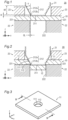
- FIG. 1 is a cross-sectional view of a processing apparatus 20 according to a first embodiment of the present invention, schematically showing its construction.
- the processing apparatus 20 is a die assembly used to shear a metal sheet.
- the processing apparatus 20 may be particularly suitably used to shear a metal sheet having a plating layer on its surface (hereinafter sometimes referred to as "surface-plated metal sheet").
- the shearing includes hole making, stamping and cutting.
- the processing apparatus 20 includes a punch 21, a die 22, and a sheet holder 23.
- the punch 21 and die 22 are positioned on one side and the other side of a workpiece constituted by a metal sheet 10, the one and the other sides being arranged in the sheet-thickness direction.
- the processing apparatus 20 uses a press, not shown, to shear the metal sheet 10 by moving at least one of the punch 21 and die 22 in the sheet-thickness direction such that the punch 21 and die 22 are located closer to each other.
- the sheet holder 23 is positioned to face the die 22, with the metal sheet 10 sandwiched in between, and prevents the metal sheet 10 from warping during shearing of the metal sheet 10 and from clinging to the punch 21 during removal of the punch 21.
- the direction represented by the sheet-thickness direction will hereinafter sometimes be referred to as z-direction, while a plane perpendicular to the z-direction will sometimes be referred to as xy-plane.
- the dimension in the sheet-thickness direction will sometimes be referred to as "height".
- the punch 21 includes an end face 211 and a side face 212 contiguous with the end face.
- the die 22 includes an end face 221 and a side face 222 contiguous with the end face.
- the end face 211 contacts the metal sheet 10 earlier during processing than the side face 212 does, and the end face 221 contacts the metal sheet 10 earlier during processing than the side face 222 does.
- the end face 211 and the end face 221 are preferably perpendicular to the sheet-thickness direction. In other words, the end faces 211 and 221 are preferably parallel to the metal sheet 10.
- a clearance CL of a predetermined size in plan view is provided between the contour of the end face 211 and the contour of the end face 221.
- the punch 21 and die 22 are positioned such that the end face 211 and the end face 221 do not overlap in plan view.
- in plan view means looking at an object exactly in one sheet-thickness direction.
- the end face 211 and the end face 221 "not overlapping in plan view” means that the end faces 211 and 221 do not overlap when the end faces 211 and 221 are projected onto a plane perpendicular to the sheet-thickness direction (i.e., an xy-plane).
- the punch 21 and die 22 may be moved closer to each other until the distance between the end faces 211 and 221 in the sheet-thickness direction is zero or less. This enables severing the metal sheet 10 in a more reliable manner. It also prevents the punch 21 and die 22 from hitting each other when the metal sheet 10 is severed.
- Each of the end faces 211 and 221 may have any shape as long as they do not overlap in plan view.
- the planar shape of the end face 211 i.e., shape in an xy-plane
- the planar shape of the end face 221 may be, for example, circular, elliptical, or rectangular.
- the planar shape of the end face 221 may be, for example, a shape with a circular hole formed therein, a shape with an elliptical hole formed therein, or a shape with a rectangular hole formed therein.
- the planar shape of the end face 221 is preferably such that the clearance CL is constant.
- the planar shape of the end face 211 is preferably circular.
- the planar shape of the end face 221 is preferably a shape with a circular hole formed therein. If a circular shape is used, the end faces constrains the material circumferentially, which can achieve uniform deformation. Thus, when a surface-plated metal sheet is sheared, good corrosion resistance is provided to the edge surface.
- the end face 211 is not limited to any particular size (i.e., surface area). However, if the end face 211 is too small, it may be unable to withstand the load during processing, and thus be damaged.
- the size of the end face 211 is preferably equivalent to a circle with a diameter of 10 mm (i.e., area of about 78 mm 2 ) is larger. On the other hand, if the end face 211 is too large, this increases the load required to push the metal sheet 10 with an inclined portion 212a, described further below, which may require use of a press with higher performance.
- the punch 21 and die 22 may be solid or may be hollow.
- the punch 21 and die 22 are preferably solid.
- the punch 21 and die 22 receive compressive stress during a push of the metal sheet 10 by the inclined portion 212a, discussed further below. Accordingly, the punch 21 and die 22 preferably have sufficient strengths for withstanding such stress.
- the side face 212 of the punch 21 includes an inclined portion 212a providing a surface inclined to face the metal sheet 10 and shaped to overlap the die 22 in plan view.
- providing a surface inclined to face the metal sheet 10 means that a normal to the surface provided by the inclined portion 212a that extends outwardly from the surface is directed toward the metal sheet 10. More specifically, it means that, where the positive z-direction is defined as the direction from the metal sheet 10 toward the position of the punch 21 and the negative z-direction is defined as the direction toward the position of the die 22, the component in the z-direction of the normal to the surface provided by the inclined portion 212a extending outwardly from the surface is negative.
- the inclined portion 212a and die 22 "overlapping in plan view” means that the inclined portion 212a and die 22 overlap when the inclined portion 212a and die 22 are projected onto a plane perpendicular to the sheet-thickness direction (i.e., an xy-plane). For the purposes of this definition, it is not necessary that the entire inclined portion 212a overlap the die 22; it is sufficient if at least a portion of the inclined portion 212a overlaps the die 22.
- the angle formed by the surface provided by the inclined portion 212a and the sheet-thickness direction, ⁇ , is not smaller than 15°. Preferable ranges of the angle ⁇ will be specified further below.
- the height of the inclined portion 212a, HT is preferably not smaller than 60 % of the sheet thickness of the metal sheet 10.
- the height HT of the inclined portion 212a is preferably not smaller than 1 mm, more preferably not smaller than 3 mm, and yet more preferably not smaller than 5 mm.
- the side face 212 of the punch 21 includes an extreme end portion 212b contiguous with the inclined portion 212a and located at an end adjacent to the metal sheet 10 as determined along the sheet-thickness direction and providing a surface generally parallel to the sheet-thickness direction.
- the angle formed by the surface provided by the extreme end portion 212b and the sheet-thickness direction is preferably not larger than 5.0°, more preferably not larger than 3.0°, yet more preferably not larger than 1.0°, and still more preferably not larger than 0.5°.
- the extreme end portion 212b enables applying large shearing stress to the metal sheet 10. This further ensures that the metal sheet 10 is severed. However, depending on the size of the clearance CL and the material of the metal sheet 10, the metal sheet 10 may be severed with no extreme end portion 212. Accordingly, it is not essential that the side face 212 include an extreme end portion 212b; the side face 212 need not include an extreme end portion 212b.
- a lower limit of the height H is preferably 1 % of the sheet thickness of the metal sheet 10, more preferably 2 %, and yet more preferably 3 %.
- a lower limit of the height H is preferably 0.03 mm, more preferably 0.06 mm, and yet more preferably 0.09 mm.
- the metal sheet 10 may be severed before the inclined portion 212a contacts the metal sheet 10. Further, there is a tendency that the smaller the height H, the later the time at which the metal sheet 10 is severed. If a surface-plated metal sheet is sheared, the later the time at which the metal sheet 10 is severed, the better corrosion resistance is provided to the edge surface, as discussed in more detail further below.
- an upper limit of the height H is preferably 50 % of the sheet thickness of the metal sheet 10, more preferably 40 %, and yet more preferably 30 %.
- An upper limit of the height H is preferably 1.6 mm, more preferably 1.2 mm, and yet more preferably 0.8 mm.
- the side face 222 of the die 22 is generally parallel to the sheet-thickness direction.
- the side face 222 of the die 22 does not include an inclined portion like the inclined portion 212a of the side face 212 of the punch 21.
- a method of manufacturing a metallic member according to the present embodiment includes the step of shearing a surface-plated metal sheet using the processing apparatus 20.
- the base material of the surface-plated metal sheet may be steel, copper, a copper alloy, aluminum, or an aluminum alloy, for example.
- the manufacturing method according to the present embodiment is particularly suitable in implementations where the base material of the surface-plated metal sheet is steel, i.e., the surface-plated metal sheet is a plated steel sheet, because steel is prone to rust and, as such, providing corrosion resistance to steel according to the present embodiment has significant advantages.
- the plated steel sheet may be, for example, a Zn-based plated steel sheet or an Al-based plated steel sheet.
- the surface-plated metal sheet is a Zn-based plated steel sheet.
- a Zn-based plating acts as a sacrificial corrosion protection for the steel sheet, i.e., base material. This prevents corrosion initiating at exposed base material at the cut edge surface resulting from the shearing, thereby further increasing the corrosion resistance of the produced metallic member.
- the Zn-based plating may be hot-dip galvanizing, galvannealing, Zn-Ni-based plating, Zn-Al-based plating, Zn-Mg-based plating, or Zn-Al-Mg-based plating, for example.
- the sheet thickness of the surface-plated metal sheet is preferably 0.2 to 9 mm. If the sheet thickness is too large, the proportion of the fracture surface after shearing may be larger, reducing the effect of improving corrosion resistance.
- An upper limit of the sheet thickness of the surface-plated steel sheet is more preferably 6 mm. On the other hand, if the sheet thickness is sufficiently small, any rust developed on the edge surface will not be noticeable and, as such, the benefit of improved corrosion resistance will be small.
- a lower limit of the sheet thickness of the surface-plated steel sheet is more preferably 1.0 mm.
- the thickness of the plating layer of the surface-plated metal sheet is preferably not smaller than 15 pm. If the plating layer is too small, the plating layer may be insufficient for covering the edge surface such that corrosion resistance may not be provided to the edge surface.
- a lower limit of the thickness of the plating layer of the surface-plated metal sheet is more preferably 30 pm.
- an upper limit of the thickness of the plating layer of the surface-plated metal sheet is 150 pm, for example.
- the step of shearing the metal sheet 10 (i.e., surface-plated metal sheet) using the processing apparatus 20 will be described referring to FIGS. 1 and 2 .
- the punch 21 and die 22 are positioned on one side and the other side, arranged in the sheet-thickness direction, of the metal sheet 10. At least one of the punch 21 and die 22 is moved in the sheet-thickness direction by a press, not shown, such that the punch 21 and die 22 are located closer to each other.
- an inclined surface 111 is formed in the metal sheet 10 by the inclined portion 212a of the punch 21, as shown in FIG. 2 .
- a cut surface 112 is formed in the edge surface of the first portion 11, contiguous with the inclined surface 111.
- the cut surface 112 includes a shear surface and a fracture surface.
- the cut surface 112 may be constituted by only one of a shear surface and a fracture surface, or no cut surface 112 may be formed at all.
- the first portion 11 including the inclined surface 111 provides a product (i.e., metallic member).
- the inclined surface 111 is formed through deformation of the surface of the metal sheet 10, which is a surface-plated metal sheet, and thus has a plating layer at least in some portions.
- the inclined surface 111 may have some of its plating layer peeled off by sliding against the punch 21, for example, but still is more likely to be covered with a plating layer than the shear surface and fracture surface. Further, the thickness of the plating layer covering the inclined surface 111 does not significantly decrease from the amount of thickness of the plating layer of the surface-plated metal sheet.
- the shear surface may be covered with a plating layer originating from the plating layer on the surface of the metal sheet 10 that has detoured and entered, or may not be covered with a plating layer.
- the fracture surface is usually not covered with a plating layer.
- the edge surface of a produced metallic member includes an inclined surface, thereby increasing the proportion of the edge surface covered with a plating layer. This provides a metallic member with improved corrosion resistance at its cut edge surface.
- the angle ⁇ ( FIG. 1 ) formed by the surface provided by the inclined portion 212a of the punch 21 and the sheet-thickness direction is not smaller than 15°.
- the later the time at which the metal sheet 10 is severed means that the metal sheet 10 is not severed until the punch 21 and die 22 are moved even closer to each other.
- the later the time at which the metal sheet 10 is severed the smaller the height of the cut surface 112 and the higher the proportion of the height of the inclined surface 111 in the sheet thickness of the metal sheet 10.
- a lower limit of the angle ⁇ is preferably 20°, and more preferably 30°.
- the larger the angle ⁇ the larger the load required to form the inclined surface 111.
- the angle ⁇ is equal to the angle of inclination of the inclined surface 111; as such, a larger angle ⁇ means a larger projection area of the formed inclined surface 111 in an xy-plane.
- An upper limit of the angle ⁇ is preferably 60°, more preferably 50°, and yet more preferably 45°.
- the first portion 11 in FIG. 2 provides a product (i.e., metallic member). After the second portion 12 is stamped out of the metal sheet 10, the remaining portion constitutes the first portion 11.
- the first portion 11 will be hereinafter referred to as metallic member 11.
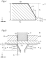
- FIG. 3 is a perspective view of the metallic member 11, and FIG. 4 is a cross-sectional view taken on line IV-IV in FIG. 3 .
- FIG. 3 shows an implementation where the hole in the metallic member 11 has a circular contour, this is merely illustrative.
- each of the end face 211 of the punch 21 and the end face 221 of the die 22 may have any planar shape. Accordingly, the contour of the hole in the metallic member 11 may have any shape.
- the metallic member 11 includes one inclined surface 111 in its edge surface.
- the metallic member 11 further includes a cut surface 112 contiguous with the inclined surface 111 and located at that one of the ends of the metallic member 11 as determined along the sheet-thickness direction at which the size of the member is increased by the inclined surface 111.
- the cut surface 112 includes a shear surface 112a providing a surface generally parallel to the sheet-thickness direction, and a fracture surface 112b.
- the shear surface 112a and the fracture surface 112b are formed in this order, beginning at the one adjacent to the inclined surface 111.
- the surfaces of the metallic member 11 except for the edge surface are covered with the plating layer 10a.
- the edge surface of the metallic member 11 at least a portion of the inclined surface 111 is covered with the plating layer 10a.
- the shear surface 112a may be covered, or may not be covered, with the plating layer 10a.
- the fracture surface 112b is usually not covered with the plating layer 10a.
- FIG. 4 shows an implementation where the entire inclined surface 111 and a portion of the shear surface 112a are covered with the plating layer 10a and base material is exposed at the remainder of the shear surface 112a and the fracture surface 112b.
- the height Ht of the inclined surface 111 is not smaller than 60 % of the sheet thickness T.
- a lower limit of the height Ht is preferably 70 % of the sheet thickness T, more preferably 80 %, and yet more preferably 90 %.
- the height Ht of the inclined surface 111 may be increased by, for example, increasing the angle ⁇ formed by the surface provided by the inclined portion 212a of the punch 21 ( FIG. 1 ) and the sheet-thickness direction, or reducing the height H of the extreme end portion 212b of the punch 21.
- the entire edge surface of the metallic member 11 may be constituted by the inclined surface 111.
- the metallic member 11 need not include a cut surface 112.
- the metallic member 11 can be manufactured in a more stable manner.
- a lower limit of the height of the cut surface 112 is preferably 3 % of the sheet thickness T, and more preferably 5 %.
- the metallic member 11 has good corrosion resistance because at least a portion of the inclined surface 111 is covered with the plating layer 10a.
- the surface-plated metal sheet is a Zn-based plated steel sheet
- the Zn-based plating layer acts as a sacrificial corrosion protection for the base material, i.e., steel sheet, which provides a certain corrosion resistance even if the proportion of the surface at which base material is exposed is relatively large.
- the angle ⁇ formed by the inclined surface 111 and the sheet-thickness direction is not smaller than 15°.
- a lower limit of the angle ⁇ is preferably 20°, and more preferably 30°.
- An upper limit of the angle ⁇ is preferably 60°, more preferably 50°, and yet more preferably 45°.
- the angle ⁇ formed by the inclined surface 111 and the sheet-thickness direction may be controlled by adjusting the shape of the punch 21 ( FIG. 1 ).
- the angle ⁇ formed by the inclined surface 111 and the sheet-thickness direction is equal to the angle ⁇ formed by the inclined portion 212a and the sheet-thickness direction.
- the plating layer 10a covering at least a portion of the inclined surface 111 is derived from the workpiece. Consequently, the plating layer 10a covering at least a portion of the inclined surface 111 has completely the same composition as the plating layer 10a covering the surfaces other than the edge surface.
- the proportion of the surface region of the inclined surface 111 covered with the plating layer 10a is preferably not lower than 60 %. More preferably, the entire inclined surface 111 is covered with the plating layer 10a.
- the thickness of the portion of the plating layer 10a covering the inclined surface 111a is preferably 25 to 90 % of the thickness of the portions of the plating layer 10a covering the surfaces other than the edge surface.
- FIG. 4 shows an implementation where the inclined surface 111 and the cut surface 112 are formed in the edge surface of the metallic member and the cut surface 112 includes a shear surface 112a and a fracture surface 112b
- the cut surface 112 may not include one of a shear surface 112a and a fracture surface 112b.
- the metallic member 11 may not have a cut surface 112.
- the processing apparatus 20, the method of manufacturing a metallic member, and the metallic member 11 according to the first embodiment of the present invention have been described.
- the present embodiment provides a metallic member with improved corrosion resistance at the cut edge surface.
- FIG. 5 is a cross-sectional view of a processing apparatus 30 according to a second embodiment of the present invention, schematically showing its construction.
- the processing apparatus 30 is different from the processing apparatus 20 according to the first embodiment ( FIG. 1 ) in the construction of the punch and die.
- the processing apparatus 30 includes a punch 31 replacing the punch 21 of the processing apparatus 20, and a die 32 replacing the die 22 of the processing apparatus 20.
- the punch 31 includes an end face 311 and a side face 312 contiguous with the end face.
- the die 32 includes an end face 321 and a side face 322 contiguous with the end face.
- a clearance CL with a predetermined size in plan view is provided between the contour of the end face 311 and the contour of the end face 321.
- the punch 31 and die 32 are positioned such that the end face 311 and the end face 321 do not overlap in plan view.
- the side face 312 of the punch 31 is generally parallel to the sheet-thickness direction.
- the side face 322 of the die 32 includes an inclined portion 322a providing a surface inclined to face the metal sheet 10 and shaped to overlap the punch 31 in plan view.
- providing a surface inclined to face the metal sheet 10 means that, more specifically, where the positive z-direction is defined as the direction from the metal sheet 10 toward the position of the punch 31 and the negative z-direction is defined as the direction toward the position of the die 32, the component in the z-direction of the normal to the surface provided by the inclined portion 322a extending outwardly from the surface is positive.
- the inclined portion 322a and punch 31 "overlapping in plan view” means that the inclined portion 322a and punch 31 overlap when the inclined portion 322a and punch 31 are projected onto a plane perpendicular to the sheet-thickness direction (i.e., an xy-plane).
- a plane perpendicular to the sheet-thickness direction i.e., an xy-plane.
- the angle ⁇ formed by the surface provided by the inclined portion 322a and the sheet-thickness direction and the height HT of the inclined portion 322a are the same as in the first embodiment.
- the side face 322 of the die 32 includes an extreme end portion 322b contiguous with the inclined portion 322a and located at an end adjacent to the metal sheet 10 as determined along the sheet-thickness direction and providing a surface generally parallel to the sheet-thickness direction.
- the height H of the extreme end portion 322b is the same as in the first embodiment. Further, as is the case with the first embodiment, the side face 322 may not include an extreme end portion 322b.
- a method of manufacturing a metallic member according to the present embodiment includes the step of shearing a surface-plated metal sheet using the processing apparatus 30.
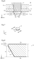
- the step of shearing the metal sheet 10 (i.e., surface-plated metal sheet) using the processing apparatus 30 will be described referring to FIGS. 5 and 6 .
- the punch 31 and die 32 are positioned on one side and the other side, arranged in the sheet-thickness direction, of the metal sheet 10. At least one of the punch 31 and die 32 is moved in the sheet-thickness direction by a press, not shown, such that the punch 31 and die 32 are located closer to each other. During this, an inclined surface 141 is formed in the metal sheet 10 by the inclined portion 322a of the die 32, as shown in FIG. 6 .
- a cut surface 142 is formed in the edge surface of the second portion 14, contiguous with the inclined surface 141.
- the cut surface 142 includes a shear surface and a fracture surface.
- the cut surface 142 may be constituted by only one of a shear surface and a fracture surface, or no cut surface 142 may be formed at all.
- the second portion 14 provides a product (i.e., metallic member).
- the edge surface of a produced metallic member includes an inclined surface 141, thereby increasing the proportion of the edge surface covered with a plating layer. This provides a metallic member with improved corrosion resistance at its cut edge surface.
- the second portion 14 in FIG. 6 provides a product (i.e., metallic member).
- the second portion 14 is stamped out of the metal sheet 10.
- the second portion 14 will be hereinafter referred to as metallic member 14.
- FIG. 7 is a perspective view of the metallic member 14, and FIG. 8 is a cross-sectional view taken on line VIII-VIII in FIG. 7 .
- FIG. 7 shows an implementation where the metallic member 14 has a circular contour, this is merely illustrative.
- the contour of the metallic member 14 may have any shape.
- the metallic member 14 includes one inclined surface 141 in its edge surface.
- the metallic member 14 further includes a cut surface 142 contiguous with the inclined surface 141 and located at that one of the ends of the metallic member 14 as determined along the sheet-thickness direction at which the size of the member is increased by the inclined surface 141.
- the cut surface 142 includes a shear surface 142a providing a surface generally parallel to the sheet-thickness direction, and a fracture surface 142b.
- the shear surface 142a and the fracture surface 142b are formed in this order, beginning at the one adjacent to the inclined surface 141.
- the surfaces except for the edge surface are covered with the plating layer 10a.
- the edge surface of the metallic member 14 at least a portion of the inclined surface 141 is covered with the plating layer 10a.
- the shear surface 142a may be covered, or may not be covered, with the plating layer 10a.
- the fracture surface 142b is usually not covered with the plating layer 10a.
- FIG. 8 shows an implementation where the entire inclined surface 111 and a portion of the shear surface 142a are covered with the plating layer 10a and base material is exposed at the remainder of the shear surface 142a and the fracture surface 142b.
- the height Ht of the inclined surface 141, the height of the cut surface 142, the angle ⁇ formed by the inclined surface 141, the sheet-thickness direction, etc. are the same as in the first embodiment.
- the height Ht of the inclined surface 141, the height of the cut surface 142, and the angle ⁇ formed by the inclined surface 141 and the sheet-thickness direction may be controlled by adjusting the shape of the die 32 ( FIG. 5 ).
- the cut surface 142 may not include one of a shear surface 142a and a fracture surface 142b, and the metallic member 14 may not have a cut surface 142.
- the processing apparatus 30, the method for manufacturing a metallic member, and the metallic member 14 according to the second embodiment of the present invention have been described. While the processing apparatus 20 according to the first embodiment ( FIG. 1 ) provides an inclined portion 212a in the side face 212 of the punch 21, the processing apparatus 30 according to the second embodiment ( FIG. 5 ) provides an inclined portion 322a in the side face 322 of the die 32. While the first embodiment provides an inclined surface 111 in the first portion 11 ( FIG. 2 ), the second embodiment provides an inclined surface 141 in the second portion 14 ( FIG. 6 ). Both embodiments produce the same effects in terms of the corrosion resistance of the edge surface.
- At least one of the side face of the punch and the side face of the die includes an inclined portion.
- the inclined portion is only required to provide a surface inclined to face the metal sheet and overlapping the other one of the punch and die in plan view.
- FIG. 9 is a cross-sectional view of a processing apparatus 40 according to a third embodiment of the present invention, schematically showing its construction.
- the processing apparatus 40 is different from the processing apparatus 20 according to the first embodiment ( FIG. 1 ) in the construction of the die.
- the processing apparatus 40 includes a die 32 replacing the die 22 of the processing apparatus 20.
- the die 32 is the same as in the processing apparatus 30 according to the second embodiment ( FIG. 5 ).
- a clearance CL of a predetermined size in plan view is provided between the contour of the end face of the punch 21 and the contour of the end face of the die 32.
- the punch 21 and die 32 are positioned such that their end faces do not overlap each other in plan view.
- an inclined portion is provided in each of the side face of the punch 21 and the side face of the die 32.
- the metal sheet 10 is severed into a first portion 11 including an inclined surface 111 and a second portion 14 including an inclined surface 141.
- each of the first and second portions 11 and 14 provides a product (i.e., metallic member).
- the processing apparatus, the method for manufacturing a metallic member, and the metallic member according to the third embodiment of the present invention have been described.
- the present embodiment too, provides a metallic member with improved corrosion resistance at its cut edge surface.
- FIG. 11 is a cross-sectional view of a processing apparatus 50 according to a fourth embodiment of the present invention, schematically showing its construction.
- the processing apparatus 50 is different from the processing apparatus 20 according to the first embodiment ( FIG. 1 ) in the construction of the punch and die.
- the processing apparatus 50 includes a punch 51 replacing the punch 21 of the processing apparatus 20, and includes a die 52 replacing the die 22 of the processing apparatus 20.
- the punch 51 includes an end face 511 and a side face 512 contiguous with the end face.
- the die 52 includes an end face 521 and a side face 522 contiguous with the end face.
- a clearance CL of a predetermined size in plan view is provided between the contour of the end face 511 and the contour of the end face 521.
- the punch 51 and die 52 are positioned such that their end faces do not overlap in plan view.
- the side face 512 of the punch 51 includes an inclined portion 521a and an extreme end portion 512b.
- the side face 522 of the die 52 is generally parallel to the sheet-thickness direction.
- the punch 51 and die 52 of the processing apparatus 52 are different from the punch 51 and die 22 of the processing apparatus 20 ( FIG. 1 ) in their planar shape.
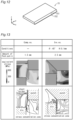
- FIG. 12 is a perspective view of a metallic member 15 produced by the processing apparatus 50.
- the metallic member 15 is produced by cutting a metal sheet along one direction perpendicular to the sheet-thickness direction (i.e., y-direction).
- the metallic member 15 includes an inclined surface 151 and a cut surface 152.
- the inclined surface 151 and cut surface 152 are the same as the inclined surface 111 and cut surface 112 of the metallic member 11 ( FIG. 3 ) except that they are different in their planar shape (i.e., shape in an xy-plane).
- the present embodiment too, provides a metallic member with improved corrosion resistance at its cut edge surface.
- FIGS. 3 and 7 illustrate implementations where the metallic member produced is the remainder of the metal sheet after a predetermined shape has been stamped out ( FIG. 3 ), and where the metallic member is the portion stamped out of the metal sheet ( FIG. 7 ).
- the same effects produced by the previously discussed embodiments are produced by implementations where a metal sheet is cut into a metallic member, as according to the present embodiment. It will be understood that the line along which the metal sheet 10 is cut need not be a straight line.
- the above embodiment illustrates an implementation where an inclined portion 512a is provided in the side face 512 of the punch 51; in other implementations, in lieu of the side face 512 of the punch 51 or in addition to the side face 512 of the punch 51, the side face 522 of the die 52 may include an inclined portion.
- a processing apparatus representing the construction of the processing apparatus 20 ( FIG. 1 ) was used to perform stamping on a metal sheet.
- the end face 211 of the punch 21 had a circular shape with a diameter of 10.0 mm, and the clearance CL was 0.05 mm (the diameter of the hole in the die 22 being 10.1 mm).
- Trial production was performed while the angle ⁇ was changed to 15°, 30° and 45° and the height H was changed to 0.1 mm, 0.4 mm and 0.8 mm.
- the workpiece was a Zn-Al-Mg-based plated steel sheet with a yield strength of 366 MPa, a tensile strength of 454 MPa, an elongation of 31 %, a sheet thickness of 3.2 mm, and an amount of adherent plating of 275 g/m 2 .
- stamping was performed on a metal sheet using a columnar punch with a diameter of 10.0 mm and a die having a columnar hole with a diameter of 10.8 mm.
- FIG. 13 shows contour diagrams each illustrating the stress distribution inside a metal sheet in the middle of the processing, calculated by the finite element method.
- the region pushed by the inclined portion was under high pressure, and a stress concentration zone was produced that extended from the shoulder of the die, parallel to the inclined portion.
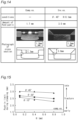
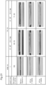
- FIG. 14 shows photographs each showing a cross section of a metal sheet immediately before fracture.
- FIG. 14 shows that, if processing was done by the processing apparatus for the inventive examples, the time at which cracking occurred was later than when processing was done by the processing apparatus for the comparative examples (i.e., cracking did not occur until the punch was pushed in deeper).
- FIG. 15 is a graph showing the relationship between the angle ⁇ and height H and the push-in limit during stamping.
- the push-in limit during stamping is the amount of push-in by the punch immediately before the metal sheet is fractured; a larger push-in limit during stamping means a later time at which the metal sheet is fractured.
- FIG. 15 shows that the larger the angle ⁇ or the smaller the height H, the larger the push-in limit during stamping.
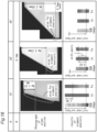
- FIG. 16 shows photographs each showing a cross section of a metal sheet after processing, as well as results of element analysis of the edge surface.
- Hp in FIG. 16 means the height of the portion of the edge surface that has a remaining plating layer thereon (hereinafter referred to as "remaining plating height Hp").
- the remaining plating height Hp was determined by measuring the edge surface of the metal sheet with energy-distribution X-ray analysis equipment (EDX) and determining the distributions of Zn and Fe on the edge surface.
- EDX energy-distribution X-ray analysis equipment
- a metal sheet processed by a punch including an inclined portion with an angle ⁇ of 30° had some of the plating layer peeled off near the lower end of the inclined surface.
- the plating layer remained all the way to the lower end of the inclined surface, although intermittently.
- FIG. 17 is a graph showing the relationship between the angle ⁇ and height H and the persistence of plating.
- the persistence of plating is the remaining plating height Hp divided by the sheet thickness.
- FIG. 17 shows a tendency that the larger the angle ⁇ or the smaller the height H, the higher the persistence of plating. It is to be noted that the persistence of plating on a metal sheet processed by the processing apparatus for the comparative examples was 20 % at the maximum.
- FIG. 18 shows photographs of metal sheets before and after atmospheric corrosion testing.
- the atmospheric corrosion testing was conducted by cutting a metal sheet in halves, applying a rust-preventive paint to the edge surfaces other than the surface to be evaluated (i.e., edge surface formed by stamping), and then placing the metal sheet outdoors.
- Each of the metal sheets processed by the processing apparatus for the comparative examples had large, conspicuous regions of red rust on the fracture surface three weeks after the initiation of exposure.
- a processing apparatus representing the construction of the processing apparatus 50 ( FIG. 11 ) was used to perform shearing to cut a metal sheet along a straight line.
- the clearance CL between the end face 511 of the punch 51 and the end face 521 of the die 52 was 0.05 mm.
- Trial production was performed while the angle ⁇ was changed to 15°, 30° and 45° and the height H was changed to 0.1 mm, 0.4 mm and 0.8 mm.
- the workpiece used was a Zn-Al-Mg-based plated steel sheet identical with that for stamping.
- a shearing die assembly with vertical side faces (with a clearance of 0.4 mm) was used to perform shearing to cut a metal sheet along a straight line.
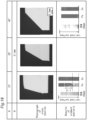
- FIG. 19 shows photographs each showing a cross section of a metal sheet after processing, as well as results of element analysis of the edge surface.
- the plating layer remained all the way to the lower end of the inclined surface.
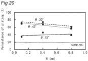
- FIG. 20 is a graph showing the relationship between the angle ⁇ and height H and the persistence of plating. It is to be noted that the persistence of plating of a metal sheet processed by the processing apparatus for the comparative examples was 18 % at the maximum.
- FIG. 21 shows photographs of metal sheets before and after atmospheric corrosion testing.
- Each of the metal sheets processed by the processing apparatus for the comparative examples had red rust on the fracture surface six weeks after the initiation of exposure.
- no red rust was produced as of six weeks after the initiation of exposure.
Landscapes
- Engineering & Computer Science (AREA)
- Mechanical Engineering (AREA)
- Chemical & Material Sciences (AREA)
- Chemical Kinetics & Catalysis (AREA)
- Materials Engineering (AREA)
- Metallurgy (AREA)
- Organic Chemistry (AREA)
- Punching Or Piercing (AREA)
- Shaping Metal By Deep-Drawing, Or The Like (AREA)
Applications Claiming Priority (2)
| Application Number | Priority Date | Filing Date | Title |
|---|---|---|---|
| JP2021213916 | 2021-12-28 | ||
| PCT/JP2022/045768 WO2023127479A1 (ja) | 2021-12-28 | 2022-12-13 | 加工装置、金属製部材の製造方法、及び金属製部材 |
Publications (2)
| Publication Number | Publication Date |
|---|---|
| EP4458488A1 true EP4458488A1 (de) | 2024-11-06 |
| EP4458488A4 EP4458488A4 (de) | 2025-06-11 |
Family
ID=86998704
Family Applications (1)
| Application Number | Title | Priority Date | Filing Date |
|---|---|---|---|
| EP22915703.7A Pending EP4458488A4 (de) | 2021-12-28 | 2022-12-13 | Verarbeitungsvorrichtung, verfahren zur herstellung eines metallelements und metallelement |
Country Status (7)
| Country | Link |
|---|---|
| US (1) | US20250018456A1 (de) |
| EP (1) | EP4458488A4 (de) |
| JP (1) | JP7617483B2 (de) |
| KR (1) | KR20240112300A (de) |
| CN (1) | CN118434516A (de) |
| MX (1) | MX2024007677A (de) |
| WO (1) | WO2023127479A1 (de) |
Families Citing this family (1)
| Publication number | Priority date | Publication date | Assignee | Title |
|---|---|---|---|---|
| WO2024247723A1 (ja) * | 2023-05-29 | 2024-12-05 | 日本製鉄株式会社 | 加工装置、金属製部材の製造方法、及び金属製部材 |
Family Cites Families (13)
| Publication number | Priority date | Publication date | Assignee | Title |
|---|---|---|---|---|
| JPS6040620A (ja) * | 1983-08-15 | 1985-03-04 | Nippon Light Metal Co Ltd | 皿絞り孔明け加工法 |
| JPS63278617A (ja) * | 1987-05-11 | 1988-11-16 | Hitachi Ltd | クラッド板材の打抜き方法 |
| JP2006263755A (ja) | 2005-03-22 | 2006-10-05 | Tdk Corp | プレス成型金属部品の製造方法及び装置 |
| JP5272518B2 (ja) | 2008-05-29 | 2013-08-28 | Jfeスチール株式会社 | 亜鉛系めっき鋼板、亜鉛系めっき鋼板の切断加工方法および切断加工用金型 |
| US9908747B2 (en) * | 2014-07-17 | 2018-03-06 | Inventio Ag | Cladding component for an escalator or a moving walkway |
| JP2016175105A (ja) | 2015-03-20 | 2016-10-06 | アスモ株式会社 | プレス加工品の製造方法 |
| JP6073025B1 (ja) | 2015-11-04 | 2017-02-01 | 日新製鋼株式会社 | 切断端面を有する表面処理鋼板の部品およびその切断加工方法 |
| CN106862374B (zh) * | 2017-03-31 | 2018-11-23 | 西安建筑科技大学 | 一种沉头孔冲压成形模具及工艺 |
| EP3586990B1 (de) * | 2018-06-22 | 2023-06-07 | Jäkel GmbH & Co. KG | Verfahren zur erhöhung der mechanischen stabilität eines randbereichs |
| JP7596060B2 (ja) | 2018-08-28 | 2024-12-09 | 日本製鉄株式会社 | 切断加工品 |
| US12311451B2 (en) * | 2019-03-12 | 2025-05-27 | Nippon Steel Corporation | Cutting method and cut article |
| KR102081888B1 (ko) * | 2019-03-15 | 2020-02-26 | 김흥규 | 펀치조절식 금형장치를 이용한 데크플레이트 제조방법 |
| JP7547033B2 (ja) | 2019-04-19 | 2024-09-09 | 日本製鉄株式会社 | 表面処理鋼板の切断加工方法 |
-
2022
- 2022-12-13 KR KR1020247019931A patent/KR20240112300A/ko active Pending
- 2022-12-13 WO PCT/JP2022/045768 patent/WO2023127479A1/ja not_active Ceased
- 2022-12-13 MX MX2024007677A patent/MX2024007677A/es unknown
- 2022-12-13 US US18/714,431 patent/US20250018456A1/en active Pending
- 2022-12-13 JP JP2023570809A patent/JP7617483B2/ja active Active
- 2022-12-13 CN CN202280084941.0A patent/CN118434516A/zh active Pending
- 2022-12-13 EP EP22915703.7A patent/EP4458488A4/de active Pending
Also Published As
| Publication number | Publication date |
|---|---|
| US20250018456A1 (en) | 2025-01-16 |
| MX2024007677A (es) | 2024-07-09 |
| CN118434516A (zh) | 2024-08-02 |
| WO2023127479A1 (ja) | 2023-07-06 |
| JPWO2023127479A1 (de) | 2023-07-06 |
| EP4458488A4 (de) | 2025-06-11 |
| KR20240112300A (ko) | 2024-07-18 |
| JP7617483B2 (ja) | 2025-01-20 |
Similar Documents
| Publication | Publication Date | Title |
|---|---|---|
| US12311451B2 (en) | Cutting method and cut article | |
| EP3689491A1 (de) | Verfahren zur bewertung der verformungsgrenze, rissvorhersageverfahren und verfahren zum entwurf einer pressmatrize | |
| JP6073025B1 (ja) | 切断端面を有する表面処理鋼板の部品およびその切断加工方法 | |
| JP6766365B2 (ja) | 金属板の耐曲げ性の評価装置および評価方法 | |
| EP4458488A1 (de) | Verarbeitungsvorrichtung, verfahren zur herstellung eines metallelements und metallelement | |
| Adamczyk et al. | Sheared edge extension of high-strength cold-rolled steels | |
| Won et al. | Effect of two-stage press blanking on edge stretchability with third-generation advanced high-strength steels | |
| US11123785B2 (en) | Surface-treated steel sheet part having cut end surface, and cutting method therefor | |
| Yoshida et al. | Evaluation and improving methods of stretch flangeability | |
| US20250222507A1 (en) | Method of manufacturing metallic member, press tool, and metallic member | |
| JPH01293922A (ja) | 金属板のバリ無打抜き型及び加工方法 | |
| US12365020B2 (en) | Method for producing blank, method for producing press-formed part, method for judging shape, program for judging shape, apparatus for producing blank, and blank | |
| JP7547033B2 (ja) | 表面処理鋼板の切断加工方法 | |
| JP2008155218A (ja) | 銅めっき鋼板の半抜き加工方法 | |
| EP4275810B1 (de) | Vorrichtung zur bewertung von schäden und verfahren zur bewertung von schäden für pressformwerkzeuge | |
| JPH0857557A (ja) | 金属板の打ち抜き型および加工方法 | |
| WO2024247723A1 (ja) | 加工装置、金属製部材の製造方法、及び金属製部材 | |
| TWI903524B (zh) | 加工裝置、金屬製構件的製造方法及金屬製構件 | |
| Benedyk et al. | The continuous bending under tension (CBT) test method for evaluating formability of sheet metal | |
| Chanhee et al. | Effect of two-stage press blanking on edge stretchability with third-generation advanced high-strength steels | |
| JP2007283342A (ja) | 突合せ溶接金属板 | |
| JPH10118725A (ja) | 疲労特性に優れた厚手鋼板の打抜方法 | |
| KR100547481B1 (ko) | 표면처리강판 절단부의 내식성 향상을 위한 다이의 구조 | |
| WO2025163984A1 (ja) | 金属板の遅れ破壊評価方法、それに使用する試験片、及び自動車部品の製造方法 | |
| CN120882512A (zh) | 金属制加工品的制造方法以及金属制加工品 |
Legal Events
| Date | Code | Title | Description |
|---|---|---|---|
| STAA | Information on the status of an ep patent application or granted ep patent |
Free format text: STATUS: THE INTERNATIONAL PUBLICATION HAS BEEN MADE |
|
| PUAI | Public reference made under article 153(3) epc to a published international application that has entered the european phase |
Free format text: ORIGINAL CODE: 0009012 |
|
| STAA | Information on the status of an ep patent application or granted ep patent |
Free format text: STATUS: REQUEST FOR EXAMINATION WAS MADE |
|
| 17P | Request for examination filed |
Effective date: 20240626 |
|
| AK | Designated contracting states |
Kind code of ref document: A1 Designated state(s): AL AT BE BG CH CY CZ DE DK EE ES FI FR GB GR HR HU IE IS IT LI LT LU LV MC ME MK MT NL NO PL PT RO RS SE SI SK SM TR |
|
| RIC1 | Information provided on ipc code assigned before grant |
Ipc: B21D 28/34 20060101ALI20250225BHEP Ipc: B21D 28/24 20060101ALI20250225BHEP Ipc: B21D 28/04 20060101AFI20250225BHEP |
|
| DAV | Request for validation of the european patent (deleted) | ||
| DAX | Request for extension of the european patent (deleted) | ||
| A4 | Supplementary search report drawn up and despatched |
Effective date: 20250509 |
|
| RIC1 | Information provided on ipc code assigned before grant |
Ipc: B21D 28/34 20060101ALI20250502BHEP Ipc: B21D 28/24 20060101ALI20250502BHEP Ipc: B21D 28/04 20060101AFI20250502BHEP |