EP4458481A1 - Mineralsortiersystem - Google Patents
Mineralsortiersystem Download PDFInfo
- Publication number
- EP4458481A1 EP4458481A1 EP22913653.6A EP22913653A EP4458481A1 EP 4458481 A1 EP4458481 A1 EP 4458481A1 EP 22913653 A EP22913653 A EP 22913653A EP 4458481 A1 EP4458481 A1 EP 4458481A1
- Authority
- EP
- European Patent Office
- Prior art keywords
- conveyor belt
- ray
- separation system
- mineral separation
- length direction
- Prior art date
- Legal status (The legal status is an assumption and is not a legal conclusion. Google has not performed a legal analysis and makes no representation as to the accuracy of the status listed.)
- Pending
Links
Images

Classifications
-
- B—PERFORMING OPERATIONS; TRANSPORTING
- B07—SEPARATING SOLIDS FROM SOLIDS; SORTING
- B07C—POSTAL SORTING; SORTING INDIVIDUAL ARTICLES, OR BULK MATERIAL FIT TO BE SORTED PIECE-MEAL, e.g. BY PICKING
- B07C5/00—Sorting according to a characteristic or feature of the articles or material being sorted, e.g. by control effected by devices which detect or measure such characteristic or feature; Sorting by manually actuated devices, e.g. switches
- B07C5/02—Measures preceding sorting, e.g. arranging articles in a stream orientating
-
- B—PERFORMING OPERATIONS; TRANSPORTING
- B07—SEPARATING SOLIDS FROM SOLIDS; SORTING
- B07C—POSTAL SORTING; SORTING INDIVIDUAL ARTICLES, OR BULK MATERIAL FIT TO BE SORTED PIECE-MEAL, e.g. BY PICKING
- B07C5/00—Sorting according to a characteristic or feature of the articles or material being sorted, e.g. by control effected by devices which detect or measure such characteristic or feature; Sorting by manually actuated devices, e.g. switches
- B07C5/34—Sorting according to other particular properties
- B07C5/3416—Sorting according to other particular properties according to radiation transmissivity, e.g. for light, x-rays, particle radiation
-
- B—PERFORMING OPERATIONS; TRANSPORTING
- B07—SEPARATING SOLIDS FROM SOLIDS; SORTING
- B07C—POSTAL SORTING; SORTING INDIVIDUAL ARTICLES, OR BULK MATERIAL FIT TO BE SORTED PIECE-MEAL, e.g. BY PICKING
- B07C5/00—Sorting according to a characteristic or feature of the articles or material being sorted, e.g. by control effected by devices which detect or measure such characteristic or feature; Sorting by manually actuated devices, e.g. switches
- B07C5/34—Sorting according to other particular properties
- B07C5/342—Sorting according to other particular properties according to optical properties, e.g. colour
-
- B—PERFORMING OPERATIONS; TRANSPORTING
- B07—SEPARATING SOLIDS FROM SOLIDS; SORTING
- B07C—POSTAL SORTING; SORTING INDIVIDUAL ARTICLES, OR BULK MATERIAL FIT TO BE SORTED PIECE-MEAL, e.g. BY PICKING
- B07C5/00—Sorting according to a characteristic or feature of the articles or material being sorted, e.g. by control effected by devices which detect or measure such characteristic or feature; Sorting by manually actuated devices, e.g. switches
- B07C5/36—Sorting apparatus characterised by the means used for distribution
- B07C5/363—Sorting apparatus characterised by the means used for distribution by means of air
-
- G—PHYSICS
- G01—MEASURING; TESTING
- G01N—INVESTIGATING OR ANALYSING MATERIALS BY DETERMINING THEIR CHEMICAL OR PHYSICAL PROPERTIES
- G01N23/00—Investigating or analysing materials by the use of wave or particle radiation, e.g. X-rays or neutrons, not covered by groups G01N3/00 – G01N17/00, G01N21/00 or G01N22/00
- G01N23/02—Investigating or analysing materials by the use of wave or particle radiation, e.g. X-rays or neutrons, not covered by groups G01N3/00 – G01N17/00, G01N21/00 or G01N22/00 by transmitting the radiation through the material
- G01N23/04—Investigating or analysing materials by the use of wave or particle radiation, e.g. X-rays or neutrons, not covered by groups G01N3/00 – G01N17/00, G01N21/00 or G01N22/00 by transmitting the radiation through the material and forming images of the material
-
- G—PHYSICS
- G01—MEASURING; TESTING
- G01N—INVESTIGATING OR ANALYSING MATERIALS BY DETERMINING THEIR CHEMICAL OR PHYSICAL PROPERTIES
- G01N23/00—Investigating or analysing materials by the use of wave or particle radiation, e.g. X-rays or neutrons, not covered by groups G01N3/00 – G01N17/00, G01N21/00 or G01N22/00
- G01N23/02—Investigating or analysing materials by the use of wave or particle radiation, e.g. X-rays or neutrons, not covered by groups G01N3/00 – G01N17/00, G01N21/00 or G01N22/00 by transmitting the radiation through the material
- G01N23/06—Investigating or analysing materials by the use of wave or particle radiation, e.g. X-rays or neutrons, not covered by groups G01N3/00 – G01N17/00, G01N21/00 or G01N22/00 by transmitting the radiation through the material and measuring the absorption
- G01N23/083—Investigating or analysing materials by the use of wave or particle radiation, e.g. X-rays or neutrons, not covered by groups G01N3/00 – G01N17/00, G01N21/00 or G01N22/00 by transmitting the radiation through the material and measuring the absorption the radiation being X-rays
-
- G—PHYSICS
- G01—MEASURING; TESTING
- G01N—INVESTIGATING OR ANALYSING MATERIALS BY DETERMINING THEIR CHEMICAL OR PHYSICAL PROPERTIES
- G01N23/00—Investigating or analysing materials by the use of wave or particle radiation, e.g. X-rays or neutrons, not covered by groups G01N3/00 – G01N17/00, G01N21/00 or G01N22/00
- G01N23/02—Investigating or analysing materials by the use of wave or particle radiation, e.g. X-rays or neutrons, not covered by groups G01N3/00 – G01N17/00, G01N21/00 or G01N22/00 by transmitting the radiation through the material
- G01N23/06—Investigating or analysing materials by the use of wave or particle radiation, e.g. X-rays or neutrons, not covered by groups G01N3/00 – G01N17/00, G01N21/00 or G01N22/00 by transmitting the radiation through the material and measuring the absorption
- G01N23/12—Investigating or analysing materials by the use of wave or particle radiation, e.g. X-rays or neutrons, not covered by groups G01N3/00 – G01N17/00, G01N21/00 or G01N22/00 by transmitting the radiation through the material and measuring the absorption the material being a flowing fluid or a flowing granular solid
-
- G—PHYSICS
- G01—MEASURING; TESTING
- G01N—INVESTIGATING OR ANALYSING MATERIALS BY DETERMINING THEIR CHEMICAL OR PHYSICAL PROPERTIES
- G01N33/00—Investigating or analysing materials by specific methods not covered by groups G01N1/00 - G01N31/00
- G01N33/24—Earth materials
Definitions
- the present disclosure generally relates to a field of mineral separation technology, and more specifically to a mineral separation system.
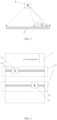
- an existing mineral separation system includes a ray source 1, a detector 2, a conveyor belt, a blowing device, and a control device.
- a principle lies in that: the ray source 1 generates X-rays and irradiates an ore block to be separated on the conveyor belt, transmitted rays are received by the detector 2 for imaging; as different mineral components in the ore block have different attenuation coefficients for the rays, an image of the ore block obtained under the irradiation of the ray source 1 of the same power has a distribution of different optical densities corresponding to different components in the ore block, then the control device analyzes and position the mineral components accordingly, and determines, according to a predetermined threshold, an ore block that needs to be separated, which is then blown and separated by the blowing device.
- a region ab is an operating region of the conveyor belt.
- the ore block to be separated is placed in the region ab. If two ore blocks (such as ore block I and ore block II) are arranged adjacent to each other on the conveyor belt, the ore block I and the ore block II may block each other since there is only one ray source 1.
- a projection region on the detector is a region cd, and the detector 2 may receive a superposition information of the ore block I and the ore block II.
- Embodiments of the present disclosure provide a mineral separation system, including a conveyor belt and at least two imaging devices, where each of the at least two imaging devices includes a ray source located above the conveyor belt and a ray detector located below the conveyor belt, the ray source and the ray detector of each imaging device are arranged facing each other in a direction perpendicular to the conveyor belt, the ray sources are staggered in a length direction of the conveyor belt and a width direction of the conveyor belt, projection regions of ray beams emitted by the ray sources do not overlap with each other, and orthographic projections of the ray beams emitted by the ray sources have an overlapping portion in the length direction of the conveyor belt.
- the conveyor belt has an operating region for placing a mineral to be separated, and an orthographic projection of the operating region in the length direction of the conveying belt falls within the overlapping portion.
- the ray source is arranged obliquely with respect to a conveying plane of the conveyor belt.
- the mineral separation system includes two imaging devices; and the ray sources of the two imaging device are respectively located on both sides of a symmetry plane in the length direction of the conveyor belt.
- the ray sources of the two imaging devices have a same distance to the symmetry plane.
- the ray sources of the imaging devices are arranged at equal intervals in the length direction and/or the width direction of the conveyor belt.
- the imaging device further includes a collimator configured to collimate a ray beam emitted by the ray source.
- the mineral separation system further includes a frame, and the ray source is rotatably connected to the frame.
- the mineral separation system further includes a blowing device and a control device, and the control device is electrically connected to the ray source, the ray detector, the conveyor belt and the blowing device.
- the blowing device includes a high-pressure nozzle, and the high-pressure nozzle includes blowing holes arranged in an array.
- the mineral separation system includes at least two imaging devices. Orthographic projections of ray beams of the imaging devices have an overlapping portion in the length direction of the conveyor belt. A region of the conveyor belt that faces the overlapping region in the width direction is used as an operating region for conveying an ore block to be separated. Each imaging device may image the ore block placed in the operating region. By imaging the same ore block from different angles using different imaging devices, it is possible to improve an accuracy of composition analysis of the ore block and improve a positioning accuracy of the ore block.
- a mineral separation system including a conveyor belt 21 and at least two imaging devices 22.
- Each imaging device 22 includes a ray source 221 located above the conveyor belt 21 and a ray detector 222 located below the conveyor belt 21.
- the ray source 221 and the ray detector 222 of each imaging device 22 are arranged facing each other in a direction perpendicular to the conveyor belt 21.
- the ray sources 221 are arranged in a stagger manner in a length direction and a width direction of the conveyor belt 21. Projection regions of ray beams of the ray sources 221 do not overlap with each other. Orthographic projections of the ray beams emitted by the ray sources 221 have an overlapping portion in the length direction of the conveyor belt 21.
- the mineral separation system includes at least two imaging devices, the orthographic projections of the ray beams emitted by the ray sources of the imaging devices have an overlapping portion in the length direction of the conveyor belt, and the conveyor belt conveys an ore block to be separated in the length direction (i.e., a conveying direction).
- an ore block may be imaged at least twice to form at least two images.
- the imaging devices may scan and image the ore block on the conveyor belt from different angles, so that an accuracy of composition analysis and a positioning precision of the ore block may be improved.
- the conveyor belt has an operating region for placing the ore block to be separated, and an orthographic projection of the operating region in the length direction of the conveying belt falls within the above-mentioned overlapping portion.
- the orthographic projection of the operating region in the length direction of the conveyor belt may completely coincide with a bottom of the overlapping portion, or the orthographic projection of the operating region in the length direction of the conveyor belt is a part of the bottom of the above-mentioned overlapping portion.
- a shaded region illustrates the overlapping portion of the orthographic projections of the ray beams emitted by the two ray sources 221 in the length direction of the conveyor belt 21.
- the operating region of the conveyor belt 21 for placing the ore block to be separated faces a region AB. Generally, the ore block to be separated in the operating region does not exceed a range of the region AB.
- the ray sources 221 are staggered in the length direction and the width direction of the conveyor belt 21, so that the imaging devices may scan and image the ore block on the conveyor belt 21 from different angles, and the problem of errors in composition analysis and positioning when imaging the ore block using a single ray source from a single angle may be overcome.
- the projection regions of the ray beams emitted by the ray sources 221 do not overlap with each other, it may be ensured that the imaging of the imaging devices do not interfere with each other and the imaging regions do not overlap with each other.
- the plurality of imaging devices may scan a same ore block to obtain a plurality of scanning images.
- a comprehensive analysis may be performed on the plurality of scanning images to obtain an average value of the composition of the ore block, thereby improving the accuracy of composition analysis.
- the plurality of scanning images may also be used for a comprehensive analysis of positions of ore blocks, which may help to improve a positioning precision of the ore block and an accuracy of positioning blowing, thereby ensuring that the separated ore block meets a separation requirement.
- the mineral separation system has a frame (not shown), which may be used to support the conveyor belt 21, the ray source 221 and the ray detector 222.
- the mineral separation system further includes a blowing device and a control device.
- the blowing device is installed on the frame, and the control device is electrically connected to the conveyor belt, the ray source, the ray detector and the blowing device.
- an orthographic projection of any ray source 221 on a conveying plane of the conveyor belt 21 falls within the conveyor belt 21.
- a distance between the orthographic projection of any ray source on the conveying plane of the conveyor belt 21 and a conveying end of the conveyor belt 21 is not less than a predetermined spacing.
- a blowing device is installed on the frame.
- the blowing device includes a high-pressure nozzle, and the high-pressure nozzle includes a plurality of blowing holes arranged in an array.
- the high-pressure nozzle is provided above the conveyor belt 21 and is used to blow a target ore block on the conveyor belt 21.
- the blowing device is movably installed on the frame, so that a blowing position may be adjusted based on a control command of the control device.
- the ray sources are located at inner sides of the conveyor belt 21, so that most of the ray beams emitted by the ray source 221 distributed near an edge of the conveyor belt 21 may irradiate the operating region of the conveyor belt 21.
- such design may allow the aforementioned overlapping portion to substantially face a middle region in the width direction of the conveyor belt 21, that is, it may be ensured that the operating region is substantially located in the middle region in the width direction of the conveyor belt 21.
- a distance between the ray source 221 of each imaging device 22 and the conveying end of the conveyor belt 21 is not less than a predetermined spacing.
- the associated control device may analyze the mineral composition according to the image for the ore block, determine a moving speed of the conveyor belt 21 according to an imaging time difference between different imaging devices and the spacing between different imaging devices, and control the corresponding blowing device to blow air before the ore block reaches the conveying end of the conveyor belt 21. If the ray source 221 is located at the conveying end of the conveyor belt 21, it is possible that the composition analysis, the positioning and the separation of the ore block have not been completed when the ore block leaves the conveyor belt 21.
- blowing device located at the conveying end of the conveyor belt 21 .
- an intermediate blowing device a blowing device between the plurality of imaging devices 22.
- an imaging device located before the intermediate blowing device After the primary blowing, it is possible to perform a composition analysis and positioning again by using an imaging device located after the intermediate blowing device, and perform a secondary blowing of ore blocks according to a corresponding scanning result and requirement, so that the accuracy of mineral separation may be further improved.
- the ray source 221 may be arranged obliquely with respect to the conveying plane of the conveyor belt 21, so that a size of the overlapping portion of the ray beams emitted by the ray sources 221 in the imaging devices 22 may be adjusted.
- the mineral separation system includes two imaging devices 22, and the ray sources 221 of the two imaging devices 22 are respectively located on both sides of a symmetry plane in the length direction of the conveyor belt 21.
- Such design may allow the aforementioned overlapping portion to substantially face the middle region in the width direction of the conveyor belt 21, so as to ensure that the operating region is substantially located in the middle region in the width direction of the conveyor belt 21, prevent the operating region from being biased to one side of the conveyor belt, and ensure that the conveyor belt 21 may convey the ore block smoothly.
- the ray sources of the two imaging devices 22 have a same distance to the symmetry plane, so that the operating region is located in the middle region in the width direction of the conveyor belt 21.
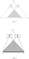
- a shaded region represents the overlapping portion of the orthographic projections of the ray beams of the two ray sources 221 in the length direction of the conveyor belt 21.
- An ore block located in the shaded region of the conveyor belt may be successively detected by the two imaging devices, an ore block located in a region CA of the conveyor belt may only be detected by a left imaging device 221, and an ore block located in a region BD of the conveyor belt may only be detected by a right imaging device 221. Therefore, the region AB is preferably used as the operating region of the conveyor belt for placing the ore block to be separated.
- the mineral separation system includes at least two imaging devices 22, and the ray sources 221 of the imaging devices 22 are arranged at equal intervals in the width direction of the conveyor belt 21.
- Such design may allow the aforementioned overlapping portion to substantially face the middle region in the width direction of the conveyor belt 21, so as to ensure that the operating region is substantially located in the middle region in the width direction of the conveyor belt 21, prevent the operating region from being biased to one side of the conveyor belt, and ensure that the conveyor belt may convey the mineral block smoothly.
- the ray sources 221 of the imaging devices 22 are arranged at equal intervals in the length direction of the conveyor belt 21.
- FIG. 4 shows a schematic diagram of a projection structure in a length direction of a mineral separation system provided by another embodiment of the present disclosure.
- each imaging device 22 further includes a collimator (not shown).
- the collimator faces the ray source in a direction perpendicular to the conveying belt 21.
- the collimator is arranged between the ray source 221 and the conveyor belt 21 to collimate a ray beam emitted by the ray source 221.
- a right field angle of a right ray source 221 may be reduced using a collimator, and a left field angle of a left ray source 221 may be reduced using a collimator, so that the field angles of the two ray sources 221 may be limited within the region AB covering the conveyor belt.
- the imaging device using the collimator is suitable for a conveyor belt with a narrow width, and the region AB as the operating region may cover an entire conveying surface of the conveyor belt.
- FIG. 5 shows a schematic diagram of a projection structure in a length direction of a mineral separation system according to another embodiment of the present disclosure.
- the mineral separation system provided by such embodiment differs from the mineral separation system in the embodiment of FIG. 3 in that the ray source is rotatably connected to the frame.
- a ray source bracket is provided on the frame, and the ray source is hinged to the ray source bracket.
- the ray source is locked to the ray source bracket through a locking member (such as screws/bolts).
- the ray sources are suitable for a conveyor belt with a narrow width, and the region AB as the operating region may cover the entire conveying surface of the conveyor belt.
- FIG. 6 shows a schematic structural diagram of a mineral separation system provided by an embodiment of the present disclosure for irradiating and imaging adjacent ore blocks.
- the mineral separation system shown in FIG. 4 is used in such embodiments.
- the mineral separation system includes two imaging devices, each imaging device includes a collimator, and the entire conveying surface of the conveyor belt is the operating region AB.
- the ore block II is partially or completely blocked by the ore block I in the projection direction of the ray beam, so that a ray information received by the corresponding ray detector is a superposition information of the ore block I and the ore block II; when the right ray source 221 is used, the ray information received by the corresponding ray detector includes the information about rays passing through the ore block I and the information about rays passing through the ore block II, so that the ore block I and the ore block II may be distinguished.
- a projection region of the ore block I on the ray detector of the right imaging device is EF
- a projection region of the ore block II on the ray detector of the right imaging device is GH.
- the use of two imaging devices may analyze the composition of adjacent arranged ore block I and ore block II more accurately, and the accuracy of composition analysis may be improved.
- the mineral separation system shown in FIG. 3 or FIG. 5 may accurately identify the composition of ore block and improve the accuracy of composition analysis; and may accurately identity the position of ore block and improve the positioning blowing precision.
- the ray source is an X-ray emitter.
- the ray source is used to emit a fan-shaped ray beam, and a field angle of the fan-shaped ray beam may be reduced by a collimator, so that a projection region of the fan-shaped ray beam may be reduced; or the ray source is used to emit a cone ray beam, which may be converted into a fan-shaped ray beam through a collimator.
- first first
- second second
- first information may also be referred to as a second information
- first information may also be referred to as a first information
Landscapes
- Health & Medical Sciences (AREA)
- General Health & Medical Sciences (AREA)
- Life Sciences & Earth Sciences (AREA)
- Chemical & Material Sciences (AREA)
- General Physics & Mathematics (AREA)
- Analytical Chemistry (AREA)
- Biochemistry (AREA)
- Physics & Mathematics (AREA)
- Immunology (AREA)
- Pathology (AREA)
- Toxicology (AREA)
- Engineering & Computer Science (AREA)
- Environmental & Geological Engineering (AREA)
- General Life Sciences & Earth Sciences (AREA)
- Geology (AREA)
- Remote Sensing (AREA)
- Food Science & Technology (AREA)
- Medicinal Chemistry (AREA)
- Analysing Materials By The Use Of Radiation (AREA)
Applications Claiming Priority (2)
| Application Number | Priority Date | Filing Date | Title |
|---|---|---|---|
| CN202111613455.7A CN114146942A (zh) | 2021-12-27 | 2021-12-27 | 矿物分选系统 |
| PCT/CN2022/125074 WO2023124389A1 (zh) | 2021-12-27 | 2022-10-13 | 矿物分选系统 |
Publications (2)
| Publication Number | Publication Date |
|---|---|
| EP4458481A1 true EP4458481A1 (de) | 2024-11-06 |
| EP4458481A4 EP4458481A4 (de) | 2025-12-31 |
Family
ID=80452061
Family Applications (1)
| Application Number | Title | Priority Date | Filing Date |
|---|---|---|---|
| EP22913653.6A Pending EP4458481A4 (de) | 2021-12-27 | 2022-10-13 | Mineralsortiersystem |
Country Status (4)
| Country | Link |
|---|---|
| EP (1) | EP4458481A4 (de) |
| CN (1) | CN114146942A (de) |
| MX (1) | MX2024007440A (de) |
| WO (1) | WO2023124389A1 (de) |
Families Citing this family (3)
| Publication number | Priority date | Publication date | Assignee | Title |
|---|---|---|---|---|
| CN114146942A (zh) * | 2021-12-27 | 2022-03-08 | 同方威视技术股份有限公司 | 矿物分选系统 |
| CN116871177B (zh) * | 2023-09-05 | 2023-11-17 | 国擎(山东)信息科技有限公司 | 一种基于多光谱技术的高岭土原矿分选方法及系统 |
| CN222318720U (zh) * | 2024-06-18 | 2025-01-07 | 常州锐奇精密测量技术有限公司 | 一种面密度全检检测机构 |
Family Cites Families (20)
| Publication number | Priority date | Publication date | Assignee | Title |
|---|---|---|---|---|
| CN2229844Y (zh) * | 1995-07-11 | 1996-06-26 | 华中理工大学 | 矿石射线分选机 |
| US6088423A (en) * | 1998-06-05 | 2000-07-11 | Vivid Technologies, Inc. | Multiview x-ray based system for detecting contraband such as in baggage |
| DE10125531A1 (de) * | 2001-05-23 | 2002-11-28 | Heimann Systems Gmbh & Co | Inspektionsanlage |
| DE102004001790A1 (de) * | 2004-01-12 | 2005-08-04 | Commodas Daten- Und Systemtechnik Nach Mass Gmbh | Vorrichtung zur Trennung von Schüttgütern |
| CN100565336C (zh) * | 2005-11-21 | 2009-12-02 | 清华大学 | 成像系统 |
| US8137976B2 (en) * | 2006-07-12 | 2012-03-20 | Varian Medical Systems, Inc. | Dual angle radiation scanning of objects |
| CN101561405B (zh) * | 2008-04-17 | 2011-07-06 | 清华大学 | 一种直线轨迹扫描成像系统和方法 |
| US20110142201A1 (en) * | 2009-12-15 | 2011-06-16 | General Electric Company | Multi-view imaging system and method |
| CN102735700B (zh) * | 2012-06-18 | 2014-08-06 | 天津三英精密仪器有限公司 | X射线显微成像系统 |
| CN103226114B (zh) * | 2013-04-02 | 2015-09-30 | 清华大学 | 多视角立体辐射成像系统及方法 |
| CN110286414A (zh) * | 2014-12-17 | 2019-09-27 | 同方威视技术股份有限公司 | 拖挂式多视角物品检查系统及其使用方法 |
| CN105784733A (zh) * | 2015-01-26 | 2016-07-20 | 公安部第研究所 | 一种通道式双视角x射线安全检查装置 |
| CN105268634A (zh) * | 2015-04-16 | 2016-01-27 | 天津美腾科技有限公司 | 一种基于智能阵列式空气喷嘴的矿物智能干选系统 |
| CN205020424U (zh) * | 2015-09-25 | 2016-02-10 | 重庆科技学院 | 基于x射线成像的矿物分选装置及矿物分选设备 |
| CN106040617A (zh) * | 2016-05-29 | 2016-10-26 | 内蒙古科技大学 | 一种放射性矿石分选机 |
| CN107677693B (zh) * | 2017-09-26 | 2020-06-09 | 同方威视技术股份有限公司 | 用于物品安全检查的扫描成像系统及其成像方法 |
| CN109821766A (zh) * | 2019-03-05 | 2019-05-31 | 天津美腾科技有限公司 | Tds智能干选机双射源识别方法及系统 |
| CN210690842U (zh) * | 2019-04-29 | 2020-06-05 | 公安部第一研究所 | 一种双视角智能化x射线安检设备 |
| CN216779483U (zh) * | 2021-12-27 | 2022-06-21 | 同方威视技术股份有限公司 | 矿物分选系统 |
| CN114146942A (zh) * | 2021-12-27 | 2022-03-08 | 同方威视技术股份有限公司 | 矿物分选系统 |
-
2021
- 2021-12-27 CN CN202111613455.7A patent/CN114146942A/zh active Pending
-
2022
- 2022-10-13 EP EP22913653.6A patent/EP4458481A4/de active Pending
- 2022-10-13 WO PCT/CN2022/125074 patent/WO2023124389A1/zh not_active Ceased
- 2022-10-13 MX MX2024007440A patent/MX2024007440A/es unknown
Also Published As
| Publication number | Publication date |
|---|---|
| EP4458481A4 (de) | 2025-12-31 |
| WO2023124389A1 (zh) | 2023-07-06 |
| CN114146942A (zh) | 2022-03-08 |
| MX2024007440A (es) | 2024-07-04 |
Similar Documents
| Publication | Publication Date | Title |
|---|---|---|
| EP4458481A1 (de) | Mineralsortiersystem | |
| EP3412210B1 (de) | Röntgenkollimator und röntgenbildgebungsvorrichtung mit verwendung davon | |
| JP5936718B2 (ja) | 粒子線回転照射装置及び粒子線治療装置 | |
| US20140314200A1 (en) | Ct security inspection system for baggage and detector arrangement thereof | |
| EP2224229A1 (de) | Armstützstruktur und strahlungsabbildungssystem mit der armstützstruktur | |
| EP3182175B1 (de) | Detektionssystem und -verfahren mit röntgendiffraktion | |
| US10388420B2 (en) | Controlling accelerator system | |
| US20110000302A1 (en) | Method for ultrasonic inspecting a substantially circumferential weld and an apparatus for carrying out such method | |
| CA2930261C (en) | Safety inspection apparatus | |
| CN104013418B (zh) | X射线ct扫描和双源ct系统 | |
| JP2019144109A (ja) | 荷電粒子ビーム検査方法 | |
| US20250035569A1 (en) | Security inspection device, security inspection system, and security inspection method | |
| US20210341398A1 (en) | Detecting backscattered electrons in a multi-beam charged particle column | |
| JPH09311112A (ja) | 欠陥検査装置 | |
| CN105806862A (zh) | 一种固定装置和安检设备 | |
| US20240249401A1 (en) | Method for determining a position of a corner region of an electrode assembly stack | |
| CN218726798U (zh) | 扫描成像设备 | |
| US6628753B2 (en) | X-ray imaging apparatus | |
| CN115508392A (zh) | 扫描成像设备和扫描成像方法 | |
| CN114121334B (zh) | 一种射线准直调整装置 | |
| JP2020068885A (ja) | X線撮影系の位置決め用ファントム | |
| CN223154834U (zh) | 一种成像系统及分选机 | |
| CN115963124A (zh) | Ct成像系统 | |
| CN117784265A (zh) | 辐射检查系统 | |
| US20250375170A1 (en) | Module for computed tomography device, and computed tomography device |
Legal Events
| Date | Code | Title | Description |
|---|---|---|---|
| STAA | Information on the status of an ep patent application or granted ep patent |
Free format text: STATUS: THE INTERNATIONAL PUBLICATION HAS BEEN MADE |
|
| PUAI | Public reference made under article 153(3) epc to a published international application that has entered the european phase |
Free format text: ORIGINAL CODE: 0009012 |
|
| STAA | Information on the status of an ep patent application or granted ep patent |
Free format text: STATUS: REQUEST FOR EXAMINATION WAS MADE |
|
| 17P | Request for examination filed |
Effective date: 20240514 |
|
| AK | Designated contracting states |
Kind code of ref document: A1 Designated state(s): AL AT BE BG CH CY CZ DE DK EE ES FI FR GB GR HR HU IE IS IT LI LT LU LV MC ME MK MT NL NO PL PT RO RS SE SI SK SM TR |
|
| DAV | Request for validation of the european patent (deleted) | ||
| DAX | Request for extension of the european patent (deleted) | ||
| A4 | Supplementary search report drawn up and despatched |
Effective date: 20251202 |
|
| RIC1 | Information provided on ipc code assigned before grant |
Ipc: B07C 5/02 20060101AFI20251126BHEP Ipc: B07C 5/34 20060101ALI20251126BHEP Ipc: B07C 5/36 20060101ALI20251126BHEP Ipc: G01N 23/04 20180101ALI20251126BHEP Ipc: G01N 23/083 20180101ALI20251126BHEP Ipc: G01N 23/12 20180101ALI20251126BHEP Ipc: G01N 33/24 20060101ALI20251126BHEP Ipc: B07C 5/342 20060101ALI20251126BHEP |