EP4456595A1 - Verfahren und vorrichtung zur bestimmung von parametern zur drahtlosen erfassung und vorrichtung - Google Patents
Verfahren und vorrichtung zur bestimmung von parametern zur drahtlosen erfassung und vorrichtung Download PDFInfo
- Publication number
- EP4456595A1 EP4456595A1 EP22909901.5A EP22909901A EP4456595A1 EP 4456595 A1 EP4456595 A1 EP 4456595A1 EP 22909901 A EP22909901 A EP 22909901A EP 4456595 A1 EP4456595 A1 EP 4456595A1
- Authority
- EP
- European Patent Office
- Prior art keywords
- parameter
- value
- target
- moment
- echo
- Prior art date
- Legal status (The legal status is an assumption and is not a legal conclusion. Google has not performed a legal analysis and makes no representation as to the accuracy of the status listed.)
- Pending
Links
Images


Classifications
-
- H—ELECTRICITY
- H04—ELECTRIC COMMUNICATION TECHNIQUE
- H04W—WIRELESS COMMUNICATION NETWORKS
- H04W24/00—Supervisory, monitoring or testing arrangements
- H04W24/02—Arrangements for optimising operational condition
-
- G—PHYSICS
- G01—MEASURING; TESTING
- G01S—RADIO DIRECTION-FINDING; RADIO NAVIGATION; DETERMINING DISTANCE OR VELOCITY BY USE OF RADIO WAVES; LOCATING OR PRESENCE-DETECTING BY USE OF THE REFLECTION OR RERADIATION OF RADIO WAVES; ANALOGOUS ARRANGEMENTS USING OTHER WAVES
- G01S7/00—Details of systems according to groups G01S13/00, G01S15/00, G01S17/00
- G01S7/02—Details of systems according to groups G01S13/00, G01S15/00, G01S17/00 of systems according to group G01S13/00
- G01S7/40—Means for monitoring or calibrating
- G01S7/4004—Means for monitoring or calibrating of parts of a radar system
- G01S7/4008—Means for monitoring or calibrating of parts of a radar system of transmitters
- G01S7/4013—Means for monitoring or calibrating of parts of a radar system of transmitters involving adjustment of the transmitted power
-
- G—PHYSICS
- G01—MEASURING; TESTING
- G01S—RADIO DIRECTION-FINDING; RADIO NAVIGATION; DETERMINING DISTANCE OR VELOCITY BY USE OF RADIO WAVES; LOCATING OR PRESENCE-DETECTING BY USE OF THE REFLECTION OR RERADIATION OF RADIO WAVES; ANALOGOUS ARRANGEMENTS USING OTHER WAVES
- G01S13/00—Systems using the reflection or reradiation of radio waves, e.g. radar systems; Analogous systems using reflection or reradiation of waves whose nature or wavelength is irrelevant or unspecified
- G01S13/88—Radar or analogous systems specially adapted for specific applications
- G01S13/89—Radar or analogous systems specially adapted for specific applications for mapping or imaging
-
- G—PHYSICS
- G01—MEASURING; TESTING
- G01S—RADIO DIRECTION-FINDING; RADIO NAVIGATION; DETERMINING DISTANCE OR VELOCITY BY USE OF RADIO WAVES; LOCATING OR PRESENCE-DETECTING BY USE OF THE REFLECTION OR RERADIATION OF RADIO WAVES; ANALOGOUS ARRANGEMENTS USING OTHER WAVES
- G01S7/00—Details of systems according to groups G01S13/00, G01S15/00, G01S17/00
- G01S7/003—Transmission of data between radar, sonar or lidar systems and remote stations
- G01S7/006—Transmission of data between radar, sonar or lidar systems and remote stations using shared front-end circuitry, e.g. antennas
-
- H—ELECTRICITY
- H04—ELECTRIC COMMUNICATION TECHNIQUE
- H04W—WIRELESS COMMUNICATION NETWORKS
- H04W28/00—Network traffic management; Network resource management
- H04W28/16—Central resource management; Negotiation of resources or communication parameters, e.g. negotiating bandwidth or QoS [Quality of Service]
-
- G—PHYSICS
- G01—MEASURING; TESTING
- G01S—RADIO DIRECTION-FINDING; RADIO NAVIGATION; DETERMINING DISTANCE OR VELOCITY BY USE OF RADIO WAVES; LOCATING OR PRESENCE-DETECTING BY USE OF THE REFLECTION OR RERADIATION OF RADIO WAVES; ANALOGOUS ARRANGEMENTS USING OTHER WAVES
- G01S7/00—Details of systems according to groups G01S13/00, G01S15/00, G01S17/00
- G01S7/02—Details of systems according to groups G01S13/00, G01S15/00, G01S17/00 of systems according to group G01S13/00
- G01S7/41—Details of systems according to groups G01S13/00, G01S15/00, G01S17/00 of systems according to group G01S13/00 using analysis of echo signal for target characterisation; Target signature; Target cross-section
-
- H—ELECTRICITY
- H04—ELECTRIC COMMUNICATION TECHNIQUE
- H04B—TRANSMISSION
- H04B7/00—Radio transmission systems, i.e. using radiation field
- H04B7/02—Diversity systems; Multi-antenna system, i.e. transmission or reception using multiple antennas
- H04B7/04—Diversity systems; Multi-antenna system, i.e. transmission or reception using multiple antennas using two or more spaced independent antennas
- H04B7/06—Diversity systems; Multi-antenna system, i.e. transmission or reception using multiple antennas using two or more spaced independent antennas at the transmitting station
Definitions
- This application relates to the field of communication and sensing technologies, and specifically, to a wireless sensing parameter determining method and apparatus, and a device.
- a future wireless communication system is expected to provide various high-precision sensing services, for example, indoor positioning for robot navigation, Wi-Fi sensing for smart households, and radar sensing for autonomous vehicles.
- Sensing and communication systems are usually independently designed and occupy different frequency bands.
- MIMO multiple input multiple output
- communication signals in the future wireless communication system usually have a high resolution in both time domain and angle domain, which makes it possible to implement high-precision sensing by using the communication signals. Therefore, it is preferable to jointly design the sensing and communication systems, to enable the systems to share the same frequency band and hardware, to improve frequency and efficiency, and reduce hardware costs.
- ISAC integrated sensing and communication
- a radar sensor in the autonomous vehicle may provide a powerful and high-resolution obstacle detection function with a resolution on the order of centimeters.
- An ISAC technology for the autonomous vehicle provides possibility to achieve high data rate communication and high-resolution obstacle detection by using the same hardware and spectrum resources.
- Application of ISAC further includes Wi-Fi-based indoor positioning and activity recognition, drone communication and sensing, extended reality (extended reality, XR), integrated radar and communication, and the like.
- Each application has different requirements, limitations, and supervision problems.
- Radar detection that is, using a reflected echo of a target to measure a distance, a speed, and an angle, may be used as one of important use cases of integrated sensing and communication.
- a radar technology in an integrated sensing and communication scenario has different constraints and application target, there are many differences between the radar technology and a conventional radar technology.
- Embodiments of this application provide a wireless sensing parameter determining method and apparatus, and a device, which can optimize system performance and use of a power resource and an aperture resource in a communication-sensing integrated scenario.
- a wireless sensing parameter determining method including:
- a wireless sensing parameter determining apparatus is provided.
- the apparatus is used in a first device and includes:
- a communication device including a processor and a memory, the memory storing a program or instructions executable on the processor, the program or instructions, when executed by the processor, performing the steps of the method according to the first aspect.
- a communication device including a processor and a communication interface.
- the processor is configured to: obtain a first value of a first parameter corresponding to a first target, where the first device or a second device detects an echo signal of a signal sent at a first moment, to determine the first target; and configure a signal parameter of the first target according to the first value of the first parameter, where the signal parameter of the first target is used for indicating signal transmission and echo signal reception at a second moment; and the signal parameter includes: signal transmit power, a transmit end aperture gain, a receive end aperture gain, a transmit beam pointing, and a receive beam pointing, where the second moment is later than the first moment; and a value of the first parameter is determined based on a first product, the first product being a product of the signal transmit power, the transmit end aperture gain, the receive end aperture gain, a cosine value of the transmit beam pointing, and a cosine value of the receive beam pointing.
- a readable storage medium stores a program or instructions, the program or instructions, when executed by a processor, implementing the steps of the method according to the first aspect.
- a chip including a processor and a communication interface, where the communication interface is coupled to the processor, and the processor is configured to run a program or instructions to implement the method according to the first aspect.
- a computer program product is provided.
- the computer program product is stored in a storage medium, and the computer program product is executed by at least one processor to implement the steps of the method according to the first aspect.
- the first device configures the signal transmit power, the transmit end aperture gain, the receive end aperture gain, the transmit beam pointing, and the receive beam pointing of the first target according to the first value of the first parameter corresponding to the first target, so that resource configuration can be optimized in a case that a sensing requirement is met, thereby optimizing performance of an integrated sensing and communication system and the user of the power resource.
- first”, second, and so on are intended to distinguish similar objects but do not necessarily indicate a specific order or sequence. It is to be understood that the term used in such a way is interchangeable in proper circumstances, so that the embodiments of this application can be implemented in other sequences than the sequence illustrated or described herein.
- the objects distinguished by “first”, “second”, and the like are usually of one type, and a quantity of objects is not limited, for example, there may be one or more first objects.
- “and/or” used in the specification and the claims represents at least one of the connected objects, and a character “/" in this specification generally indicates an "or” relationship between the associated obj ects.
- LTE long term evolution
- LTE-Advanced LTE-advanced
- LTE-A Long term evolution
- CDMA code division multiple access
- time division multiple access time division multiple access
- FDMA frequency division multiple access
- OFDMA orthogonal frequency division multiple access
- SC-FDMA single-carrier frequency-division multiple access
- system and “network” are usually interchangeably used, and the technology described herein can be applied to the systems and wireless technologies mentioned above, and can also be applied to other systems and wireless technologies.
- technologies are also applicable to applications other than NR system applications, for example, a 6th generation (6th Generation, 6G) communication system, a new radio (new radio, NR) system is exemplarily described in the following descriptions, and the term “NR” is used in most of the following descriptions.
- 6G 6th generation
- NR new radio
- FIG. 1 shows a block diagram of a wireless communication system to which an embodiment of this application is applicable.
- the communication system includes a terminal 11 and a network side device 12.
- the terminal 11 may be a terminal side device such as a mobile phone, a tablet personal computer (tablet personal computer), a laptop computer (laptop computer) or notebook computer, a personal digital assistant (personal digital assistant, PDA), a palmtop computer, a notebook, an ultra-mobile personal computer (ultra-mobile personal computer, UMPC), a mobile Internet device (mobile Internet device, MID), an augmented reality (augmented reality, AR)/virtual reality (virtual reality, VR) device, a robot, a wearable device (a wearable device), a vehicle user equipment (vehicle user equipment, VUE), a pedestrian user equipment (pedestrian user equipment, PUE), a smart household (which is a household device having a wireless communication function, for example, a refrigerator, a television, a washing machine, or furniture), a game console, a personal
- the wearable device includes: a smart watch, a smart bracelet, a smart headset, smart glasses, smart jewelry (a smart bangle, a smart chain bracelet, a smart ring, a smart necklace, a smart ankle bangle, a smart anklet, or the like), a smart wristband, smart clothing, and the like.
- the network side device 12 may include an access network device or a core network device.
- the access network device 12 may also be referred to as a radio access network device, a radio access network (radio access network, RAN), a radio access network function, or a radio access network unit.
- the access network device 12 may include a base station, a wireless local area network (wireless local area network, WLAN) access point, a Wi-Fi node, or the like.
- the base station may be referred to as a NodeB, an evolved NodeB (eNB), an access point, a base transceiver station (base transceiver station, BTS), a radio base station, a radio transceiver, a basic service set (basic service set, BSS), an extended service set (extended service set, ESS), a home NodeB, a home evolved NodeB, a transmitting receiving point (transmitting receiving point, TRP), or another suitable term in the field.
- the base station is not limited to a specific technical term as long as the same technical effect is achieved. It is to be noted that, in the embodiments of this application, the base station in the NR system is only used as an example for description, but a specific type of the base station is not limited.
- a radar technology may use a monostatic radar mode, or may use a bistatic radar mode.
- signal receiving and transmission share an antenna, and a received signal and a transmitted signal enter different radio frequency processing links through a circulator.
- detection with no blind zone may be implemented by using continuous wave signal waveforms.
- a prerequisite is that the received signal and the transmitted signal need to be quite isolated, and isolation of about 100 dB is usually required, to eliminate submerging of the received signal caused by leakage of the transmitted signal.
- signal processing may be performed through filter matching (pulse compression), to obtain a higher signal processing gain.
- radar signal processing is based on known information
- radar signal processing may be performed by using some known information such as a synchronization signal, a reference signal, and the like.
- a blur diagram of the signal waveform is no longer in a thumbtack shape, but in a pegboard shape, a delay and a Doppler blur degree may be increased, and a gain of a main lobe is greatly reduced compared with that in the monostatic radar mode, reducing a range for measuring distances and speeds.
- An appropriate parameter set is designed, so that the range for measuring distances and speeds can meet measurement requirements of common targets such as a car, a pedestrian, and the like.
- measurement precision of the bistatic radar is related to a location of a transceiver station relative to the target, and therefore, it is necessary to select an appropriate transceiver station to improve detection performance.
- a first device may be a base station, a transmission and receiving point (transmission and receiving point, TRP), a user equipment (user equipment, UE), an access point (access point, AP), a reconfigurable intelligence surface (reconfigurable intelligence surface, RIS), or the like.
- TRP transmission and receiving point
- UE user equipment
- AP access point
- RIS reconfigurable intelligence surface
- the wireless sensing parameter determining method provided in the embodiments of this application may be understood as a joint adaptation method of transmit power, an antenna aperture, and a beam direction.
- FIG. 2 is a flowchart of steps of a wireless sensing parameter determining method according to an embodiment of this application.
- the parameter determining method includes the following steps:
- Step 201 A first device obtains a first value of a first parameter corresponding to a first target, where the first device or a second device detects an echo signal of a signal sent at a first moment, to determine the first target;
- Step 202 The first device configures a signal parameter of the first target according to the first value of the first parameter, where the signal parameter of the first target is used for indicating signal transmission and echo signal reception at a second moment, where the signal parameter includes: signal transmit power, a transmit end aperture gain, a receive end aperture gain, a transmit beam pointing, and a receive beam pointing, where
- a value of the first parameter is determined based on a first product, the first product being a product of the signal transmit power, the transmit end aperture gain, the receive end aperture gain, a cosine value of the transmit beam pointing, and a cosine value of the receive beam pointing.
- the first moment mentioned in this embodiment of this application may be understood as at least one first sensing frame
- the second moment may be understood as at least one second sensing frame.
- Transmission, receiving, and signal processing on a signal are all implemented by using a sensing frame as a time unit.
- signal parameters of signals in the same sensing frame do not change, and an adaptive adjustment method for a signal parameter provided in this embodiment of this application is used to adjust signal parameters in a next one or more sensing frames.
- the transmit end aperture gain is the same as the receive end aperture gain
- the transmit beam pointing is the same as the receive beam pointing.
- the transmit end aperture gain may be the same as or different from the receive end aperture gain
- the transmit beam pointing may be the same as or different from the receive beam pointing.
- the transmit power, the aperture gain, and the beam direction jointly determine signal power of a target reflected echo, to determine a maximum effect distance under a signal to noise ratio requirement and a signal to noise ratio (signal to noise ratio, SNR) under an effect distance.
- SNR signal to noise ratio
- a monostatic radar (or referred to as a single-station radar) meets the following relationship: P r , R 4 , SNR ⁇ P t ⁇ G 2 cos ⁇ 2 P t and P r respectively represent transmit power and received power, R represents a target distance, SNR represents a target echo signal to noise ratio, G represents a monostatic radar aperture gain, and ⁇ represents a monostatic radar beam direction.
- a bistatic radar (or referred to as a dual-station radar) meets the following relationship: P r , R t 2 R r 2 , SNR ⁇ P t ⁇ G t cos ⁇ t ⁇ G r cos ⁇ r P t and P r respectively represent the transmit power and the received power, R t and R r respectively represent a distance between a target and a transmitter and a distance between the target and a receiver, G t and G r respectively represent the transmit end aperture gain and the receive end aperture gain, and use a real value as a unit (not using dB as a unit); and ⁇ t and ⁇ r respectively represent the transmit beam pointing and the receive beam pointing.
- the first parameter is defined.
- joint adaptive adjustment on the transmit power, the aperture gain, and the beam direction in this embodiment of this application is performed based on a requirement of the first parameter.
- P t ⁇ G t cos ⁇ t ⁇ G r cos ⁇ r represents the first parameter;
- P t represents the transmit power, and
- G t and G r respectively represent the transmit end aperture gain and the receive end aperture gain;
- ⁇ t and ⁇ r respectively represent the transmit beam pointing and the receive beam pointing.
- G t G r
- ⁇ r ⁇ r .
- step 201 includes:
- the first value of the first parameter may be determined by the first device, or may be determined by the second device and then sent to the first device.
- a manner in which the second device determines the first value of the first parameter is the same as a manner in which the first device determines the first value of the first parameter. Therefore, only the manner in which the first device determines the first value of the first parameter is described below, and the manner in which the second device determines the first value of the first parameter is not repeated again.
- the first device is a transmit end device of a signal, or a receive end device of a signal, or a sensing function network element.
- the sensing function network element mentioned in this embodiment of this application is a network node that is in a core network and/or a radio access network and that is responsible for at least one function such as sensing request processing, sensing resource scheduling, sensing information exchange, and sensing data processing, may be a network node updated based on an access and mobility management function (access and mobility management function, AMF) or a location management function (location management function, LMF) in an existing 5th generation mobile communication technology (5th generation mobile communication technology, 5G) network, or may be another existing or newly defined network node.
- AMF access and mobility management function
- LMF location management function
- 5G 5th generation mobile communication technology
- the network nodes are collectively referred to as sensing function network elements in this application.
- the transmit end device and the receive end device mentioned in this embodiment of the present invention are the same device in the monostatic radar scenario, and are different devices in the bistatic radar scenario.
- a device that determines the first value of the first parameter and a device that configures the signal parameter may be the same or different.
- the device that determines the first value of the first parameter is the transmit end device, and the device that configures the signal parameter may be the transmit end device, the receive end device, or the sensing function network element. This is not specifically limited herein. If the device that determines the first value of the first parameter and the device that configures the signal parameter are different devices, the device that determines the first value of the first parameter needs to send the first parameter adjustment information to the device that configures the signal parameter.
- the method further includes:
- the method further includes:
- the method further includes:
- a connection relationship and a corresponding information exchange method between the sensing function network element, the transmit end device, and the receive end device may include the following three cases:
- a connection relationship between the sensing function network element and the transmit end device is generally direct communication, that is, information exchange may be directly performed between the two.
- the connection relationship between the two may be connection through a third-party device, so that information exchange may be performed between the two through the third-party device.
- the determining, by the first device, the first value of the first parameter corresponding to the first target includes:
- an adjustment objective of adaptive adjustment on the first parameter is to enable the echo signal quality of the first target to meet a sensing requirement.
- a location of the sensing target is approximately equal to a radio carrier station (radio carrier station, RCS).
- RCS radio carrier station
- the echo signal quality of the target is directly proportional to the first parameter, and in this embodiment of this application, adaptive adjustment on the first parameter is performed according to the echo signal quality of the target.
- the echo signal quality of the first target includes at least one of the following:
- the power of the echo signal of the first target includes at least one of the following:
- the objective of performing adaptive adjustment on the first parameter according to the echo signal quality of the first target includes the following objectives.
- An objective 1 is to maintain the echo signal quality of the first target near a first preset echo quality.
- An expression may be P r 0 ⁇ P r , where P r 0 is the preset first preset echo quality, and ⁇ P r is an allowable echo quality error.
- an objective 2 is to maintain the echo signal quality of the first target within a first echo quality range.
- An expression of the preset first echo quality range may be [ P r min , P r max ], where P r min is a lower limit of the first echo quality range, and P r max is an upper limit of a preset echo signal power range.
- the method further includes:
- a method for determining the preset echo signal power value includes:
- the method for determining the lower limit of the echo signal power range includes:
- a method for determining the upper limit of the echo signal power range includes:
- the determining, by the first device, the first value of the first parameter according to echo signal quality of the first target at the first moment includes:
- the determining the first value of the first parameter according to the second value of the first parameter, the echo signal quality of the first target at the first moment, and first preset echo quality includes:
- the determining the first value of the first parameter according to the second value of the first parameter, the echo signal quality of the first target at the first moment, and a first echo quality range includes:
- the determining, by the first device, the first value of the first parameter according to a predicted distance value of the first target at the second moment and echo signal quality of the first target at the first moment includes:
- a trajectory prediction method is used to obtain a predicted distance value at a next moment: a distance R' of the first target relative to the monostatic radar (in the monostatic radar scenario); or a distance of the first target relative to the transmitter and a distance R r ′ of the first target relative to the receiver (in the bistatic radar scenario).
- prediction on the distance of the first target at the second moment is based on maintaining a movement trajectory of the first target, and the predicted distance value at the second moment is obtained by predicting a location of the first target at the second moment.
- the premise assumption of the prediction method is that when the first target is tracked, since a movement speed of a typical target (for example, a vehicle, a pedestrian, or the like) of the communication-sensing integrated application is low relative to a sensing update rate, a target status change between two consecutive radar detections is relatively small.
- the small change in the target state mainly means that a change in a target RCS is relatively small. It may be considered that the target RCS remains almost unchanged in two consecutive or several consecutive radar detections.
- target's maneuver is small, that is, an acceleration is small, the location and the speed of the target do not greatly change, and a linear filtering algorithm such as Kalman filtering can be used.
- sensing channel properties large-scale and small-scale fading properties
- do not greatly change especially the small-scale fading property does not greatly change.
- the prediction method is content implemented by a device. This is not limited herein.
- the determining the first value of the first parameter according to the second value of the first parameter, the echo signal quality of the first target at the first moment, first preset echo quality, and the predicted distance value of the first target at the second moment includes:
- the determining the first value of the first parameter according to the second value of the first parameter, the echo signal quality of the first target at the first moment, a first echo quality range, and the predicted distance value of the first target at the second moment includes:
- step 202 includes:
- the configuring, by the first device, the transmit beam pointing and the receive beam pointing according to a first angle of the first target relative to a transmit end device and a second angle of the first target relative to a receive end device includes:
- the first angle is an angle of the first target at the first moment relative to the transmit end device
- the second angle is an angle of the first target at the first moment relative to the receive end device.
- the first angle is an angle predicted value of the first target at the second moment relative to the transmit end device
- the second angle is an angle predicted value of the first target at the second moment relative to the receive end device.
- the angle prediction method is content implemented by a device. This is not limited herein.
- the resolution requirement in the sensing requirement includes: an angle measurement resolution requirement and/or a radar imaging lateral resolution requirement.
- Angle measurement resolution It is a minimum angle between two targets that can be distinguished through radar detection, and may be measured in degrees or radians.
- Lateral resolution It is a minimum distance between two targets that can be distinguished through radar imaging in a direction perpendicular to the line of sight, and may be measured in meters.
- the quantity of antenna array elements and the arrangement of array elements determine a beam width, which further determines the angle measurement resolution.
- the angle measurement resolution is determined by the receive end device.
- the aperture D includes two cases below.
- Case B For a sparse antenna array, D depends on a spacing between array elements at two ends in the azimuth direction or the pitch direction.
- An antenna aperture adaptation method is described using 64 antennas of NR as an example. Considering that the 64 antennas are arranged in an 8 ⁇ 8 array in hardware, apertures in the azimuth direction may be set to include 1 to 8 antenna array element widths, and apertures in the pitch direction may be set to include 1 to 8 antenna array element widths.
- apertures in the azimuth direction or the pitch direction include 2 to 4 antenna array element widths
- two cases, namely, a dense array and a sparse array are further included, and there is an equivalent relationship in the angle measurement resolution, as shown in FIG. 6 .
- 2-element sparse array According to different spacings between the array elements, when the two array elements are separated by 2 to 7 array elements, the array may be respectively equivalent to a dense array of 3 to 8 array elements.
- 3-element sparse array According to different spacings between the array elements, when every two adjacent array elements are separated by 2 array elements, the array may be equivalent to a 5-element dense array; and when every two adjacent array elements are separated by 3 array elements, the array may be equivalent to a 7-element dense array.
- 4-element sparse array When every two adjacent array elements are separated by 2 array elements, the array may be equivalent to a 7-element dense array.
- the determining, by the first device, a lower limit of a transmit end antenna aperture and a lower limit of a receive end antenna aperture according to an antenna aperture of a resolution requirement in a sensing requirement, and the determined transmit beam pointing and the determined receive beam pointing at the second moment includes:
- the angle measurement resolution in the azimuth direction or the pitch direction may be set in 8 levels, as shown in Table 1: Aperture D Angle measurement resolution Aperture settings
- Option 1 1 array element - 2d 1 / 2 ⁇ k ⁇ / dcos ⁇
- 2 2 array element - 3d 1 / 3 ⁇ k ⁇ / dcos ⁇
- Option 3a 3 array elements
- Option 3b 2-element sparse array (separated by 2 array elements) 4d 1/4 ⁇ k ⁇ / dcos ⁇
- 4a 4 array elements
- Option 4b 2-element sparse array (separated by 3 array elements) 5d 1/5 ⁇ k ⁇ / dcos ⁇
- 5a 5 array elements
- Option 5b 2-element sparse array (separated by 4 array elements)
- Option 5c 3-element sparse array
- Option Aperture offset value Option 1 0,1,2,3,4,5,6,7 Option 2 0,1,2,3,4,5,6 Option 3a/3b 0,1,2,3,4,5 Option 4a/4b 0,1,2,3,4 Option 5a/5b/5c 0,1,2,3 Option 6a/6b 0,1,2 Option 7a/7b/7c/7d 0,1 Option 8a/8b 0
- a total of 14 bits may be used to transmit aperture configuration information, as shown in Table 3: Table 3 Transmission encoding on aperture settings and aperture offsets Aperture settings in the azimuth direction Aperture offset in the azimuth direction Aperture settings in the pitch direction Aperture offset in the pitch direction bit0 to bit3 bit4 to bi6 bit7 to bit10 bit11 to bit13
- the aperture settings and the aperture offsets may also be combined for encoding configuration, to reduce a quantity of bits occupied by the aperture configuration information.
- the option 1 has 1 aperture setting, and 8 aperture offsets have a total of 8 cases
- the option 2 has 1 aperture setting, and 7 aperture offsets have a total of 7 cases
- the option 3 has 2 aperture settings, and 6 aperture offsets have a total of 12 cases
- the option 4 has 2 aperture settings, and 5 aperture offsets have a total of 10 cases
- the option 5 has 3 aperture settings, and 4 aperture offsets have a total of 12 cases
- the option 6 has 2 aperture settings, and 3 aperture offsets have a total of 6 cases
- the option 7 has 4 aperture settings, and 2 aperture offsets have a total of 8 cases
- the option 8 has 2 aperture settings, and 1 aperture offset has a total of 2 cases. Therefore, there are 65 cases in total, and 7 bits may be used to transmit the aperture configuration information.
- the determining, by the first device, a lower limit of a transmit end antenna aperture and a lower limit of a receive end antenna aperture according to an antenna aperture of a resolution requirement in a sensing requirement, and the determined transmit beam pointing and the determined receive beam pointing at the second moment includes:
- the transmit beam pointing at the second moment a first distance of the first target relative to the transmit end device, and a second distance of the first target relative to the receive end device.
- a relative distance between the detection device and the sensing target changes.
- a beam broadening effect may also reduce the angle measurement resolution.
- the angle measurement resolution needs to be adaptively adjusted according to changes in the distance to the target, that is, the antenna aperture is adjusted.
- the angle measurement resolution needs to be increased (where a value of the angle measurement resolution is reduced), that is, the antenna aperture is increased, to maintain the horizontal distance resolution of radar imaging.
- the angle measurement resolution may be reduced (where the value of the angle measurement resolution is increased), that is, the antenna aperture is reduced, to release some antenna resources.
- Adjustment on the antenna aperture includes:
- Link adaptive adjustment on the antenna aperture may be performed in segments based on a relative distance R between a target and a radar, and a target angle (a beam direction) ⁇ in combination with a hardware configuration of the antenna array. For each segment, the following relationship should be met: k ⁇ D cos ⁇ ⁇ ⁇ L cross R D represents an antenna aperture in the azimuth direction or the pitch direction, ⁇ represents a wavelength, ⁇ represents a beam direction, and k represents a beam width factor, and R represents the relative distance between the target and the radar; and ⁇ L cross represents the radar imaging lateral resolution requirement.
- the 8 ⁇ 8 antenna array is still used as an example, link adaptation is set according to the target distance and an angle segmented aperture, as shown in Table 4: Table 4 Table of a correspondence between a distance, an angle segmentation, and aperture settings Relative distance R segment Aperture D settings R cos ⁇ ⁇ ⁇ L cross d k ⁇ Option 1 ⁇ L cross d k ⁇ ⁇ R cos ⁇ ⁇ 2 ⁇ L cross d k ⁇ Option 2 2 ⁇ L cross d k ⁇ ⁇ R cos ⁇ ⁇ 3 ⁇ L cross d k ⁇ Option 3a/3b 3 ⁇ L cross d k ⁇ ⁇ R cos ⁇ ⁇ 4 ⁇ L cross d k ⁇ Option 4a/4b 4 ⁇ L cross d k ⁇ ⁇ R cos ⁇ ⁇ 5 ⁇ L cross d k ⁇ Option 5a/5b/5c 5 ⁇ L cross d k ⁇ ⁇ R cos ⁇ ⁇ 6 ⁇ L cross d k ⁇ Option 6a/6b 6
- the configuring, by the first device, the signal transmit power, the transmit end aperture gain, and the receive end aperture gain according to the lower limit of the transmit end antenna aperture, the lower limit of the receive end antenna aperture, the transmit beam pointing, and the receive beam pointing, to meet the first value of the first parameter includes:
- the beam direction in the first parameter is obtained. Further, it is necessary to set the transmit power and the aperture gain in the first parameter, or a product of the transmit power and the aperture gain (that is, a power aperture product).
- the configuring the signal transmit power, the transmit end aperture gain, and the receive end aperture gain at the second moment includes:
- the first device determines to configure the signal transmit power, the transmit end aperture gain, and the receive end aperture gain by using the power priority manner or the aperture priority manner.
- a manner for configuring the transmit end aperture gain and/or the receive end aperture gain includes: prioritizing the transmit end aperture gain or prioritizing the receive end aperture gain, where
- the first device determines to configure the aperture gain in a transmit end aperture gain priority manner or in a receive end aperture gain priority manner.
- configuration priorities of the transmit power and the aperture gain are sorted in descending order:
- the aperture gain is classified into the transmit end aperture gain and the receive end aperture gain, and configuration priorities are sorted in descending order:
- a lower limit of the aperture gain is an aperture gain corresponding to the lower limit of the antenna aperture set in the previous step, and an upper limit of the aperture gain includes at least one of the following:
- the lower limit of the transmit power is minimum power required by the communication function, and the maximum transmit power includes at least one of the following:
- the transmit power may be set in a continuous setting manner, that is, any value within a preconfigured power interval may be set to the value of the transmit power.
- the transmit power may be set in a step setting manner, that is, a corresponding transmit power is set at a step interval within a preconfigured power interval.
- a method for increasing the aperture gain is to increase a quantity of occupied antenna array elements, including the following two steps:
- the first device configures the signal transmit power, the transmit end aperture gain, the receive end aperture gain, the transmit beam pointing, and the receive beam pointing corresponding to the first target according to the first value of the first parameter corresponding to the first target, so that resource configuration can be optimized in a case that a sensing requirement is met, thereby optimizing performance of an integrated sensing and communication system and the user of the power resource.
- Example 1 Joint adaption on multi-parameters in the monostatic radar
- Example 2 Joint adaption on multi-parameters in the bistatic radar
- An execution entity of the wireless sensing parameter determining method provided in the embodiments of this application may be a wireless sensing parameter determining apparatus.
- the wireless sensing parameter determining apparatus provided in the embodiments of this application is described in the embodiments of this application by using an example in which the wireless sensing parameter determining apparatus performs the wireless sensing parameter determining method.
- FIG. 7 is a schematic diagram of a structure of a wireless sensing parameter determining apparatus 700 according to an embodiment of this application.
- the apparatus is used in a first device and includes:
- the first obtaining module includes:
- the apparatus further includes: a first sending module, configured to send, to a receive end device, the receive end aperture gain and the receive beam pointing that indicate echo signal reception at the second moment;
- the apparatus further includes: a second sending module, configured to send, to a transmit end device, the signal transmit power, the transmit end aperture gain, and the transmit beam pointing that indicate the signal transmission at the second moment;
- the apparatus further includes: a third sending module, configured to send, to a transmit end device, the signal transmit power, the transmit end aperture gain, and the transmit beam pointing that indicate the signal transmission at the second moment, and send, to a receive end device, the receive end aperture gain and the receive beam pointing that indicate echo signal reception at the second moment.
- a third sending module configured to send, to a transmit end device, the signal transmit power, the transmit end aperture gain, and the transmit beam pointing that indicate the signal transmission at the second moment, and send, to a receive end device, the receive end aperture gain and the receive beam pointing that indicate echo signal reception at the second moment.
- the apparatus further includes: a fourth sending module, configured to send the signal according to the signal transmit power, the transmit end aperture gain, and the transmit beam pointing.
- the apparatus further includes: a receiving module, configured to receive the echo signal according to the receive end aperture gain and the receive beam pointing.
- the first obtaining submodule includes:
- the echo signal quality of the first target includes at least one of the following:
- the first determining unit includes:
- the first determining subunit is further configured to:
- the second determining subunit is further configured to:
- the second determining unit includes:
- the third determining subunit is further configured to:
- the fourth determining subunit is further configured to:
- the first configuration module includes:
- the first configuration submodule includes:
- the resolution requirement in the sensing requirement includes: an angle measurement resolution requirement and/or a radar imaging lateral resolution requirement.
- the determining submodule includes:
- the second configuration submodule includes:
- the second configuration unit includes:
- a manner for configuring the transmit end aperture gain and/or the receive end aperture gain includes: prioritizing the transmit end aperture gain or prioritizing the receive end aperture gain, where
- the first device configures the signal transmit power, the transmit end aperture gain, the receive end aperture gain, the transmit beam pointing, and the receive beam pointing corresponding to the first target according to the first value of the first parameter, so that resource configuration can be optimized in a case that a sensing requirement is met, thereby optimizing performance of an integrated sensing and communication system and the user of the power resource.
- the wireless sensing parameter determining apparatus provided in the embodiments of this application is an apparatus that can perform the wireless sensing parameter determining method, and all embodiments of the wireless sensing parameter determining method are applicable to the terminal and can achieve the same or similar beneficial effects.
- the wireless sensing parameter determining apparatus in this embodiment of this application may be an electronic device, for example, an electronic device with an operating system, or may be a component in an electronic device, for example, an integrated circuit or a chip.
- the electronic device may be a terminal, or may be another device other than a terminal.
- the terminal may include but is not limited to a type of the terminal 11 listed above, and the another device may be a server, a network attached storage (network attached storage, NAS), or the like. This is not specifically limited in the embodiments of this application.
- the wireless sensing parameter determining apparatus provided in the embodiments of this application can implement the processes implemented in the method embodiment of FIG. 1 to FIG. 6 and achieve the same technical effect. To avoid repetition, details are not described herein again.
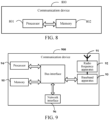
- an embodiment of this application further provides a communication device 800, including a processor 801 and a memory 802, the memory 802 storing a program or instructions runnable on the processor 801, the program or instructions, when executed by the processor 801, implementing the steps of the embodiments of the wireless sensing parameter determining method, and achieving the same technical effect. To avoid repetition, details are not described herein again.
- An embodiment of this application further provides a communication device, including a processor and a communication interface.
- the processor is configured to: obtain a first value of a first parameter corresponding to a first target, where the first device or a second device detects an echo signal of a signal sent at a first moment, to determine the first target; and configure a signal parameter of the first target according to the first value of the first parameter, where the signal parameter of the first target is used for indicating signal transmission and echo signal reception at a second moment; and the signal parameter includes: signal transmit power, a transmit end aperture gain, a receive end aperture gain, a transmit beam pointing, and a receive beam pointing, where the second moment is later than the first moment; and a value of the first parameter is determined based on a first product, the first product being a product of the signal transmit power, the transmit end aperture gain, the receive end aperture gain, a cosine value of the transmit beam pointing, and a cosine value of the receive beam pointing.
- the embodiment of the communication device corresponds
- the network side device 900 includes an antenna 91, a radio frequency apparatus 92, a baseband apparatus 93, a processor 94, and a memory 95.
- the antenna 91 is connected to the radio frequency apparatus 92.
- the radio frequency apparatus 92 receives information by using the antenna 91, and sends the received information to the baseband apparatus 93 for processing.
- the baseband apparatus 93 processes to-be-processed information, and sends the information to the radio frequency apparatus 92.
- the radio frequency apparatus 92 processes received information and sends the information by using the antenna 91.
- the method performed by the network side device may be implemented in the baseband apparatus 93.
- the baseband apparatus 93 includes a baseband processor.
- the baseband apparatus 93 may include, for example, at least one baseband plate.
- a plurality of chips are arranged on the baseband plate. As shown in FIG. 9 , one of the plurality of chips is, for example, the baseband processor, and is connected to the memory 95 through a bus interface, to invoke a program in the memory 95 to perform operations performed by the network side device in the foregoing method embodiment.
- the network side device may further include a network interface 96.
- the interface is, for example, a common public radio interface (common public radio interface, CPRI).
- the network side device 900 in this embodiment of this application further includes: instructions or a program stored in the memory 95 and executable on the processor 94, and the processor 94 invokes the instructions or program in the memory 95 to perform the method performed by the modules shown in FIG. 7 , and can achieve the same technical effect. To avoid repetition, details are not described herein again.
- An embodiment of this application further provides a readable storage medium, storing a program or instructions, the program or instructions, when executed by a processor, implementing the processes of the embodiments of the wireless sensing parameter determining method, and achieving the same technical effect. To avoid repetition, details are not described herein again.
- the processor is a processor in the terminal in the foregoing embodiments.
- the readable storage medium includes a computer-readable storage medium, for example, a read-only memory (read-only memory, ROM), a random access memory (random access memory, RAM), a magnetic disk, an optical disk, or the like.
- An embodiment of this application further provides a chip, including a processor and a communication interface coupled to each other, the processor being configured to run a program or instructions to implement the processes of the embodiments of the wireless sensing parameter determining method, and can achieve the same technical effects. To avoid repetition, details are not described herein again.
- the chip mentioned in this embodiment of this application may also be referred to as a system-level chip, a system chip, a chip system, a system on chip, or the like.
- An embodiment of this application further provides a computer program product, where the computer program product is stored in a readable storage medium, and the computer program product is configured to be executed by at least one processor to implement the processes of the embodiments of the wireless sensing parameter determining method, and can achieve the same technical effects. To avoid repetition, details are not described herein again.
- the computer software product is stored in a storage medium (such as a read-only memory (ROM)/random access memory (RAM), a magnetic disk, or an optical disc), and includes several instructions for instructing a terminal (which may be a mobile phone, a computer, a server, an air conditioner, a network device, or the like) to perform the method described in the embodiments of this application.
- a storage medium such as a read-only memory (ROM)/random access memory (RAM), a magnetic disk, or an optical disc
- a terminal which may be a mobile phone, a computer, a server, an air conditioner, a network device, or the like
Landscapes
- Engineering & Computer Science (AREA)
- Remote Sensing (AREA)
- Radar, Positioning & Navigation (AREA)
- Computer Networks & Wireless Communication (AREA)
- Physics & Mathematics (AREA)
- General Physics & Mathematics (AREA)
- Signal Processing (AREA)
- Electromagnetism (AREA)
- Quality & Reliability (AREA)
- Radar Systems Or Details Thereof (AREA)
- Mobile Radio Communication Systems (AREA)
Applications Claiming Priority (2)
| Application Number | Priority Date | Filing Date | Title |
|---|---|---|---|
| CN202111580756.4A CN116347468A (zh) | 2021-12-22 | 2021-12-22 | 无线感知的参数确定方法、装置及设备 |
| PCT/CN2022/139835 WO2023116588A1 (zh) | 2021-12-22 | 2022-12-19 | 无线感知的参数确定方法、装置及设备 |
Publications (2)
| Publication Number | Publication Date |
|---|---|
| EP4456595A1 true EP4456595A1 (de) | 2024-10-30 |
| EP4456595A4 EP4456595A4 (de) | 2025-04-09 |
Family
ID=86879266
Family Applications (1)
| Application Number | Title | Priority Date | Filing Date |
|---|---|---|---|
| EP22909901.5A Pending EP4456595A4 (de) | 2021-12-22 | 2022-12-19 | Verfahren und vorrichtung zur bestimmung von parametern zur drahtlosen erfassung und vorrichtung |
Country Status (4)
| Country | Link |
|---|---|
| US (1) | US20240345218A1 (de) |
| EP (1) | EP4456595A4 (de) |
| CN (1) | CN116347468A (de) |
| WO (1) | WO2023116588A1 (de) |
Families Citing this family (4)
| Publication number | Priority date | Publication date | Assignee | Title |
|---|---|---|---|---|
| CN116774158B (zh) * | 2023-07-06 | 2024-06-21 | 南京能智电子科技有限公司 | 一种雷达发射功率调节系统 |
| WO2025065340A1 (zh) * | 2023-09-27 | 2025-04-03 | 华为技术有限公司 | 天线资源分配方法及通信装置 |
| CN117880967A (zh) * | 2023-12-07 | 2024-04-12 | 南方科技大学 | 波束处理方法、装置、电子设备及计算机可读存储介质 |
| CN121028028A (zh) * | 2025-10-29 | 2025-11-28 | 东海实验室 | 一种海杂波数据获取方法和海杂波测试雷达系统 |
Family Cites Families (12)
| Publication number | Priority date | Publication date | Assignee | Title |
|---|---|---|---|---|
| JP2004158911A (ja) * | 2002-11-01 | 2004-06-03 | Murata Mfg Co Ltd | セクタアンテナ装置および車載用送受信装置 |
| WO2018086246A1 (zh) * | 2016-11-14 | 2018-05-17 | 华为技术有限公司 | 一种功率控制方法及终端 |
| CN109995405A (zh) * | 2017-12-29 | 2019-07-09 | 索尼公司 | 用于无线通信系统的电子设备、方法、装置和存储介质 |
| US11408973B2 (en) * | 2018-09-27 | 2022-08-09 | Google Llc | Controlling radar transmissions within a licensed frequency band |
| US11921233B2 (en) * | 2018-10-02 | 2024-03-05 | Metawave Corporation | Adaptive radar for near-far target identification |
| US11296764B2 (en) * | 2019-05-08 | 2022-04-05 | Qualcomm Incorporated | Beamforming repeaters with digitally assisted interference mitigation |
| CN112748425B (zh) * | 2019-10-31 | 2026-01-23 | 华为技术有限公司 | 感知方法及装置 |
| CN112769719A (zh) * | 2020-12-01 | 2021-05-07 | 华南理工大学 | 基于智能反射表面辅助无线通信系统渐进式信道估计方法 |
| CN113452498B (zh) * | 2021-06-23 | 2022-08-16 | 东南大学 | 单站全双工通信感知一体化信号设计与处理方法 |
| CN113747365B (zh) * | 2021-08-30 | 2023-05-12 | 中国联合网络通信集团有限公司 | 一种通信方法及装置 |
| CN113825236B (zh) * | 2021-09-03 | 2023-08-01 | 浙江大学 | 一种无线网络中感知、计算和通信的融合方法 |
| EP4198560A1 (de) * | 2021-12-17 | 2023-06-21 | Koninklijke Philips N.V. | Drahtloses kommunikationssystem mit verteilter erfassungsfähigkeit |
-
2021
- 2021-12-22 CN CN202111580756.4A patent/CN116347468A/zh active Pending
-
2022
- 2022-12-19 EP EP22909901.5A patent/EP4456595A4/de active Pending
- 2022-12-19 WO PCT/CN2022/139835 patent/WO2023116588A1/zh not_active Ceased
-
2024
- 2024-06-23 US US18/751,281 patent/US20240345218A1/en active Pending
Also Published As
| Publication number | Publication date |
|---|---|
| CN116347468A (zh) | 2023-06-27 |
| US20240345218A1 (en) | 2024-10-17 |
| EP4456595A4 (de) | 2025-04-09 |
| WO2023116588A1 (zh) | 2023-06-29 |
Similar Documents
| Publication | Publication Date | Title |
|---|---|---|
| US20240272269A1 (en) | Sensing signal detection method, sensing signal detection processing method, and related device | |
| EP4456595A1 (de) | Verfahren und vorrichtung zur bestimmung von parametern zur drahtlosen erfassung und vorrichtung | |
| US20240310473A1 (en) | Sensing signal transmission processing method and apparatus, and related device | |
| US20240337726A1 (en) | Sensing method and apparatus, sensing configuration method and apparatus, and a communication device | |
| US20250039725A1 (en) | Sensing measurement method and apparatus, and related device | |
| WO2023236005A1 (en) | Target path based beam measurement and report | |
| US20240340806A1 (en) | Transmit power determining method and apparatus, and device | |
| KR20230032994A (ko) | 무선 통신 시스템에서 통신 및 감지를 위한 전력 제어 및 빔 관리 | |
| US20240353522A1 (en) | Wireless sensing parameter determination method and apparatus and device | |
| US20250016624A1 (en) | Sensing processing method and apparatus, communication device, and readable storage medium | |
| CN116055015A (zh) | 感知信号的处理方法、装置及通信设备 | |
| US20240373254A1 (en) | Sensing method and apparatus, and communication device | |
| WO2023040747A1 (zh) | 感知信号传输处理方法、装置、电子设备及可读存储介质 | |
| US20240340949A1 (en) | Sensing method and apparatus and communication device | |
| US20250286637A1 (en) | Signal transmission method, apparatus, and communication device | |
| US20250080960A1 (en) | Wireless sensing switching method and device | |
| WO2025054003A1 (en) | Beam squint radar operation with reconfigurable intelligent surface device | |
| WO2024174246A1 (en) | Devices, methods, and apparatuses for joint communication and sensing | |
| WO2023104106A1 (zh) | 检测及配置参考信号的方法、装置、终端及网络侧设备 | |
| WO2024012237A1 (zh) | 感知处理方法、装置、终端及设备 | |
| CN119519771A (zh) | 多输入多输出mimo感知方法、装置及通信设备 | |
| EP4496409B1 (de) | Erfassungsverarbeitungsverfahren und -vorrichtung | |
| US20250301362A1 (en) | Information processing method, information transmission method, and communication device | |
| WO2025216923A1 (en) | Channel state information (csi) for joint communication and radar sensing | |
| WO2025124241A1 (zh) | 感知处理方法、装置、终端及网络侧设备 |
Legal Events
| Date | Code | Title | Description |
|---|---|---|---|
| STAA | Information on the status of an ep patent application or granted ep patent |
Free format text: STATUS: THE INTERNATIONAL PUBLICATION HAS BEEN MADE |
|
| PUAI | Public reference made under article 153(3) epc to a published international application that has entered the european phase |
Free format text: ORIGINAL CODE: 0009012 |
|
| STAA | Information on the status of an ep patent application or granted ep patent |
Free format text: STATUS: REQUEST FOR EXAMINATION WAS MADE |
|
| 17P | Request for examination filed |
Effective date: 20240718 |
|
| AK | Designated contracting states |
Kind code of ref document: A1 Designated state(s): AL AT BE BG CH CY CZ DE DK EE ES FI FR GB GR HR HU IE IS IT LI LT LU LV MC ME MK MT NL NO PL PT RO RS SE SI SK SM TR |
|
| REG | Reference to a national code |
Ref country code: DE Ref legal event code: R079 Free format text: PREVIOUS MAIN CLASS: H04W0024020000 Ipc: G01S0007000000 |
|
| DAV | Request for validation of the european patent (deleted) | ||
| DAX | Request for extension of the european patent (deleted) | ||
| A4 | Supplementary search report drawn up and despatched |
Effective date: 20250311 |
|
| RIC1 | Information provided on ipc code assigned before grant |
Ipc: G01S 7/41 20060101ALN20250305BHEP Ipc: G01S 7/40 20060101ALI20250305BHEP Ipc: G01S 7/00 20060101AFI20250305BHEP |