EP4455793A2 - Belichtungsvorrichtung, belichtungsverfahren und artikelherstellungsverfahren - Google Patents
Belichtungsvorrichtung, belichtungsverfahren und artikelherstellungsverfahren Download PDFInfo
- Publication number
- EP4455793A2 EP4455793A2 EP24169851.3A EP24169851A EP4455793A2 EP 4455793 A2 EP4455793 A2 EP 4455793A2 EP 24169851 A EP24169851 A EP 24169851A EP 4455793 A2 EP4455793 A2 EP 4455793A2
- Authority
- EP
- European Patent Office
- Prior art keywords
- region
- measurement
- substrate
- exposure
- controller
- Prior art date
- Legal status (The legal status is an assumption and is not a legal conclusion. Google has not performed a legal analysis and makes no representation as to the accuracy of the status listed.)
- Pending
Links
Images




Classifications
-
- G—PHYSICS
- G03—PHOTOGRAPHY; CINEMATOGRAPHY; ANALOGOUS TECHNIQUES USING WAVES OTHER THAN OPTICAL WAVES; ELECTROGRAPHY; HOLOGRAPHY
- G03F—PHOTOMECHANICAL PRODUCTION OF TEXTURED OR PATTERNED SURFACES, e.g. FOR PRINTING, FOR PROCESSING OF SEMICONDUCTOR DEVICES; MATERIALS THEREFOR; ORIGINALS THEREFOR; APPARATUS SPECIALLY ADAPTED THEREFOR
- G03F9/00—Registration or positioning of originals, masks, frames, photographic sheets or textured or patterned surfaces, e.g. automatically
- G03F9/70—Registration or positioning of originals, masks, frames, photographic sheets or textured or patterned surfaces, e.g. automatically for microlithography
- G03F9/7003—Alignment type or strategy, e.g. leveling, global alignment
- G03F9/7046—Strategy, e.g. mark, sensor or wavelength selection
-
- G—PHYSICS
- G03—PHOTOGRAPHY; CINEMATOGRAPHY; ANALOGOUS TECHNIQUES USING WAVES OTHER THAN OPTICAL WAVES; ELECTROGRAPHY; HOLOGRAPHY
- G03F—PHOTOMECHANICAL PRODUCTION OF TEXTURED OR PATTERNED SURFACES, e.g. FOR PRINTING, FOR PROCESSING OF SEMICONDUCTOR DEVICES; MATERIALS THEREFOR; ORIGINALS THEREFOR; APPARATUS SPECIALLY ADAPTED THEREFOR
- G03F7/00—Photomechanical, e.g. photolithographic, production of textured or patterned surfaces, e.g. printing surfaces; Materials therefor, e.g. comprising photoresists; Apparatus specially adapted therefor
- G03F7/70—Microphotolithographic exposure; Apparatus therefor
- G03F7/708—Construction of apparatus, e.g. environment aspects, hygiene aspects or materials
- G03F7/7085—Detection arrangement, e.g. detectors of apparatus alignment possibly mounted on wafers, exposure dose, photo-cleaning flux, stray light, thermal load
-
- G—PHYSICS
- G03—PHOTOGRAPHY; CINEMATOGRAPHY; ANALOGOUS TECHNIQUES USING WAVES OTHER THAN OPTICAL WAVES; ELECTROGRAPHY; HOLOGRAPHY
- G03F—PHOTOMECHANICAL PRODUCTION OF TEXTURED OR PATTERNED SURFACES, e.g. FOR PRINTING, FOR PROCESSING OF SEMICONDUCTOR DEVICES; MATERIALS THEREFOR; ORIGINALS THEREFOR; APPARATUS SPECIALLY ADAPTED THEREFOR
- G03F7/00—Photomechanical, e.g. photolithographic, production of textured or patterned surfaces, e.g. printing surfaces; Materials therefor, e.g. comprising photoresists; Apparatus specially adapted therefor
- G03F7/70—Microphotolithographic exposure; Apparatus therefor
- G03F7/70691—Handling of masks or workpieces
- G03F7/70716—Stages
-
- G—PHYSICS
- G03—PHOTOGRAPHY; CINEMATOGRAPHY; ANALOGOUS TECHNIQUES USING WAVES OTHER THAN OPTICAL WAVES; ELECTROGRAPHY; HOLOGRAPHY
- G03F—PHOTOMECHANICAL PRODUCTION OF TEXTURED OR PATTERNED SURFACES, e.g. FOR PRINTING, FOR PROCESSING OF SEMICONDUCTOR DEVICES; MATERIALS THEREFOR; ORIGINALS THEREFOR; APPARATUS SPECIALLY ADAPTED THEREFOR
- G03F7/00—Photomechanical, e.g. photolithographic, production of textured or patterned surfaces, e.g. printing surfaces; Materials therefor, e.g. comprising photoresists; Apparatus specially adapted therefor
- G03F7/70—Microphotolithographic exposure; Apparatus therefor
- G03F7/70691—Handling of masks or workpieces
- G03F7/70716—Stages
- G03F7/70725—Stages control
-
- G—PHYSICS
- G03—PHOTOGRAPHY; CINEMATOGRAPHY; ANALOGOUS TECHNIQUES USING WAVES OTHER THAN OPTICAL WAVES; ELECTROGRAPHY; HOLOGRAPHY
- G03F—PHOTOMECHANICAL PRODUCTION OF TEXTURED OR PATTERNED SURFACES, e.g. FOR PRINTING, FOR PROCESSING OF SEMICONDUCTOR DEVICES; MATERIALS THEREFOR; ORIGINALS THEREFOR; APPARATUS SPECIALLY ADAPTED THEREFOR
- G03F7/00—Photomechanical, e.g. photolithographic, production of textured or patterned surfaces, e.g. printing surfaces; Materials therefor, e.g. comprising photoresists; Apparatus specially adapted therefor
- G03F7/70—Microphotolithographic exposure; Apparatus therefor
- G03F7/70691—Handling of masks or workpieces
- G03F7/70775—Position control, e.g. interferometers or encoders for determining the stage position
-
- G—PHYSICS
- G03—PHOTOGRAPHY; CINEMATOGRAPHY; ANALOGOUS TECHNIQUES USING WAVES OTHER THAN OPTICAL WAVES; ELECTROGRAPHY; HOLOGRAPHY
- G03F—PHOTOMECHANICAL PRODUCTION OF TEXTURED OR PATTERNED SURFACES, e.g. FOR PRINTING, FOR PROCESSING OF SEMICONDUCTOR DEVICES; MATERIALS THEREFOR; ORIGINALS THEREFOR; APPARATUS SPECIALLY ADAPTED THEREFOR
- G03F9/00—Registration or positioning of originals, masks, frames, photographic sheets or textured or patterned surfaces, e.g. automatically
- G03F9/70—Registration or positioning of originals, masks, frames, photographic sheets or textured or patterned surfaces, e.g. automatically for microlithography
- G03F9/7003—Alignment type or strategy, e.g. leveling, global alignment
- G03F9/7023—Aligning or positioning in direction perpendicular to substrate surface
- G03F9/7034—Leveling
Definitions
- the present invention relates to an exposure apparatus, an exposure method, and an article manufacturing method.
- stepper As an exposure apparatus used in the manufacture of a semiconductor device or the like, there are a step-and-repeat type exposure apparatus (stepper) and a step-and-scan type exposure apparatus (scanner).
- the stepper is a low cost apparatus as compared to the scanner, and used in a step in which high resolution and high precision overlay are not required.
- a height measurement apparatus measures the distance from a projection lens. The stage is focused on the projection lens in accordance with the measurement value, and then exposure is performed.
- Japanese Patent No. 6491833 discloses a height measurement apparatus that measures the height of a sample based on the projection image of a two-dimensional slit.
- the two-dimensional slit includes a plurality of slits arrayed at a fine pitch, and measurement light beams having passed through the respective slits are received by a two-dimensional light receiving element.
- the present invention provides a technique advantageous in achieving both measurement accuracy and throughput regarding height measurement of a substrate surface.
- the present invention in its first aspect provides an exposure apparatus as specified in claims 1 to 14.
- the present invention in its second aspect provides an exposure method as specified in claim 15.
- the present invention in its third aspect provides an article manufacturing method as specified in claim 16.
- Fig. 1 is a view showing the arrangement of an exposure apparatus 100 according to the first embodiment.
- the exposure apparatus 100 is one form of a lithography apparatus used in a photolithography process as a device or flat panel manufacturing process.
- the exposure apparatus 100 projects the pattern of an original onto a substrate by a projection optical system, and exposes the substrate.
- the exposure apparatus 100 is a step-and-repeat type exposure apparatus or a step-and-scan type exposure apparatus, and exposes a substrate via an original (mask), thereby transferring the pattern of the mask to the substrate.
- the exposure method is not limited, but a description will be given below assuming that the exposure apparatus 100 is a step-and-repeat type exposure apparatus.
- An illumination optical system 102 guides light from a light source 101 and illuminates a mask 103 serving as an original.
- the light source 101 can be formed by an i-line mercury lamp, an excimer laser, or the like.
- a pattern to be projected is drawn in the mask 103.
- the light having passed through the mask 103 reaches a substrate 108 on a stage 105 through a projection optical system 104.
- the stage 105 is a substrate stage that moves while holding the substrate 108.
- the image of the mask pattern projected onto the substrate 108 causes reaction of a photosensitive material such as a resist applied on the surface of the substrate 108 in advance. By developing it, a pattern is formed on the surface of the substrate 108.
- a position measurement apparatus such as an interferometer or an encoder (not shown) measures the position and posture of the stage 105 with high accuracy. With this, overlay exposure with high accuracy is implemented.
- a measurement device 106 measures the height of the substrate 108, and at least one of the height and tilt of the stage 105 is controlled based on the measurement result. Note that, in the following description, controlling at least one of the height and tilt of the stage 105 will be sometimes simply referred to as "height position adjustment of the substrate”.
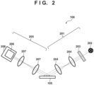
- the measurement device 106 detects the height of a point of interest in a detection region.
- the measurement device 106 includes a light projector 201 and a light receiver 205.
- the light projector 201 can include a light source 202 that makes light obliquely enter the surface of an object (substrate 108) on the stage 105, a two-dimensionally arrayed light projection pattern 203, and a light projecting optical system 204 used to project the light projection pattern 203 to the object.
- the light projecting optical system 204 need not be provided depending on the kind of the light source 202 and the distance between the light projection pattern 203 and the object.
- the light projection pattern 203 and the object may be set in the relationship of a Scheimpflug optical system by using the light projecting optical system 204.
- the measurement accuracy can be improved by focusing the entire surface of the light projection pattern 203 on the object. Further, when measuring the height of the object, it can be prevented that a local tilt of the object causes a change of the measurement value.
- the light receiver 205 can include a light receiving optical system 207 and a camera 208.
- the light reflected by the object enters the camera 208 via the light receiving optical system 207.
- the camera 208 can include a light receiving element 206 that includes a plurality of two-dimensionally arrayed pixels.
- the light receiving optical system 207 need not be provided depending on the kind of the light source 202 and the distance between the object and the camera 208.
- the object and the light receiving element 206 may be set in the relationship of a Scheimpflug optical system by using the light receiving optical system 207.
- the measurement accuracy can be improved by focusing the entire surface of object on the light receiving element 206. Further, when measuring the height of the object, it can be prevented that a local tilt of the object causes a change of the measurement value.
- Respective components of the exposure apparatus 100 including the measurement device 106, the stage 105, and the projection optical system 104 are connected to a controller 107.
- the controller 107 can be formed by, for example, a computer apparatus including a processor (CPU) and a memory.
- the controller 107 can store information of the height and tilt of the substrate measured by the measurement device 106, and the like, and control the stage 105 by issuing a driving instruction to the stage 105.
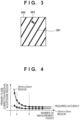
- Fig. 3 shows an example of a light projection pattern 301 projected onto the substrate.
- the light projection pattern 203 in the light projector 201 is projected onto an exposure region 302 serving as the precision inspection region of the substrate 108.
- the light projection pattern 301 corresponding to the light projection pattern 203 appears.
- the light projection pattern 301 includes a plurality of slit images.
- a pattern interval 303 of the light projection pattern 301 needs to be as narrow as possible.
- the light receiving element 206 is a two-dimensional light receiving element, the height map information of the entire exposure region can be obtained with the measurement interval defined by the light projection pattern 301 on the substrate and the size of the light receiving element.
- the measurement device 106 measures, at a plurality of measurement points in the exposure region, the height position of the substrate 108 held by the stage 105. After that, based on the result of the measurement by the measurement device 106, the controller 107 corrects the position of the stage 105 (height position adjustment) such that the shift amount of the height position of the substrate 108 with respect to the image plane of the projection optical system 104 is decreased.
- the height position adjustment of the substrate during exposure is performed by controlling the height and tilt of the stage 105. Therefore, even if the height map in the exposure region is measured in detail, control is performed only on the primary plane components in the height and tilt directions.
- the controller 107 determines the required number of measurement points based on the relationship, obtained in advance, between the number of measurement points and the correction residual by correction of the position of the stage 105 for each size of the exposure region, and determines the number of divisions of the exposure region in accordance with the determined required number of measurement points.
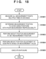
- Fig. 4 is a graph illustrating the relationship between the number of measurement points in height measurement in the exposure region and the primary plane correction residual in the exposure region. Fig. 4 shows the relationship in a case in which the size of the exposure region (shot region) is of 26 mm ⁇ 33 mm, and the relationship in a case in which the size of the exposure region is of 10 mm ⁇ 10 mm.
- the required accuracy is determined from the depth of focus of the projection lens.
- the number of measurement points is determined such that the primary plane correction residual becomes smaller than that corresponding to the required accuracy.
- the number of measurement points needs to be b or more for the primary plane correction residual smaller than that corresponding to the required accuracy.
- the number of measurement points may be a or more smaller than b for the primary plane correction residual smaller than that corresponding to the required accuracy.
- the controller 107 sets a plurality of measurement points such that one measurement point is assigned to each of a plurality of sub-regions obtained by dividing the exposure region based on the position or size of the exposure region.
- a method of dividing the exposure region in this embodiment will be described. As shown in Fig. 4 described above, the number of measurement points A required for height position measurement is obtained from the size of the exposure region. Based on the required number of measurement points A thus obtained, the number of divisions N is determined as follows:
- the controller 107 divides the exposure region with the number of divisions N thus determined, and sets the plurality of measurement points such that one measurement point is assigned to each of the plurality (N) of sub-regions thus obtained. In an example, the controller 107 determines the center of the sub-region as the measurement position as shown in Fig. 6 .
- the controller 107 performs height position measurement using the measurement device 106 at a plurality of measurement positions determined as described above. Based on the result measured by the measurement device 106, the controller 107 performs position correction of the stage 105 such that the substrate surface matches the focal position of the projection optical system 104, that is, the shift amount of the height position of the substrate surface with respect to the image plane of the projection optical system 104 is decreased. After that, the controller 107 executes exposure.
- the controller 107 divides the exposure region based on the size of the exposure region such that features in the exposure region can be acquired, and performs height position measurement for each of a plurality of sub-regions obtained by the division. With this, it is possible to shorten the data transfer time and processing time without sacrificing measurement accuracy.
- the method of dividing the measurement region so as to obtain squarely arranged measurement positions has been described as an example, but the division method is not limited to this. It is possible to employ various methods that equally arrange the measurement positions.
- the controller 107 divides the exposure region based on the position of the exposure region such that features in the exposure region can be acquired, and performs height position measurement for each of a plurality of sub-regions obtained by the division.
- a plurality of chip pattern regions are formed in the mask.
- the number of chip pattern regions is arbitrary.
- the plurality of chip pattern regions include the same pattern.
- One chip pattern region corresponds to one chip (die) to be manufactured.
- a normal shot region (exposure region) has a size where all of the plurality of chip pattern regions of the mask can be projected.
- the plurality of sub-regions correspond to the plurality of chip regions.
- the exposure region is one region of interest of a plurality of shot regions of the substrate 108.
- the plurality of shot regions of the substrate 108 can include full shot regions located in the central portion of the substrate, and partial shot regions located in the outer peripheral portion of the substrate.
- the full shot region has a size where the entire pattern region of the mask 103 is transferred. Accordingly, the full shot region includes the plurality of chip regions corresponding to the plurality of chip pattern regions of the mask 103.
- the partial shot region has a size where only a part of the pattern region of the mask 103 is transferred. Particularly, the partial shot region includes one or more chip regions corresponding to only some of the plurality of chip pattern regions of the mask 103.
- a shape change is sometimes larger than in the full shot region due to the influence of roll-off, warping, sagging, or the like.
- a region division method is set that can accurately acquire the feature of a sharp height change in the partial shot region. Note that an increase in the number of measurement positions along with an increase in the number of divisions leads to an increase in processing time. Therefore, in this example, the measurement positions are determined in accordance with the shape of the partial shot region so as not to change the number of divisions.
- Figs. 10A and 10B show an example of division of the partial shot region.
- Fig. 10A shows an example of division of the full shot region.
- the controller 107 divides only the region within the substrate into n equal parts in the vertical and horizontal directions, as shown in Fig. 10B .
- the center of each sub-region in the substrate is set as the measurement position.
- Fig. 20 illustrates a flowchart of an exposure method according to this embodiment.
- the controller 107 assigns measurement points to the exposure region.
- a plurality of measurement points are set in the above-described method such that one measurement point is assigned to each of a plurality of sub-regions obtained by dividing the exposure region based on the position or size of the exposure region.
- the controller 107 performs height position measurement of the substrate 108 held by the stage 105 at the plurality of measurement points in the exposure region on the substrate.
- step S3 based on the measurement result in step S2, the controller 107 corrects the position of the stage 105 such that the shift amount of the height position of the substrate 108 with respect to the image plane of the projection optical system 104 is decreased. After the position of the stage is corrected, the controller 107 exposes the exposure region in step S4.
- Fig. 12 illustrates a flowchart of an exposure method in the second embodiment.
- the example has been described in which the region of interest is divided into equal parts.
- fine protrusions and recesses and materials having different reflectances coexist due to wiring patterns such as various kinds of circuit patterns.
- the shape of reflected light largely changes at a portion where the step of the protrusion/recess sharply changes or the position of the wiring pattern having a high reflectance, and the measurement accuracy can deteriorate.
- a controller 107 accurately measures the height position in the entire area of a predetermined one sample shot region of a plurality of shot regions in the substrate.
- Fig. 13 shows an example of the height distribution (height map) obtained in advance by measuring the height positions in one sample shot region (sample region). According to the height map, it can be seen that recesses and protrusions (changes in height position) exist in the exposure region. The measurement accuracy in a case in which height position measurement is performed in a portion where the height position sharply changes is lower than the measurement accuracy in a case in which height position measurement is performed in a portion where the height position is flat.
- step S1202 the controller 107 determines the positions of a plurality of measurement points in the exposure region based on the height distribution obtained in step S1201, as shown in Fig. 13 .
- the controller 107 sets, as the position of the measurement point, the position where the change amount of the height position in the height distribution is smaller than a predetermined value in one exposure region.
- Fig. 14 shows an example of partial regions in one sample shot region, in each of which precision measurement of height position is performed.
- the size of the partial region can be determined based on the minimum measurement unit defined from the measurement resolution of a light receiver 205.
- the height map can be obtained from a set of height measurement values of respective partial regions.
- the controller 107 can obtain the differential value of the measurement values in adjacent partial regions, and set, as the measurement position, the partial region where the differential value is equal to or smaller than a predetermined threshold value T1.
- the controller 107 executes processing of obtaining the height distribution in the sample region (processing of performing height position measurement in each partial region) a plurality of times to obtain the information of measurement reproducibility. Based on the obtained information of measurement reproducibility, the controller 107 determines positions of a plurality of measurement points in the exposure region. For example, the controller 107 determines, as the measurement position, the partial region where the measurement reproducibility is high.
- the measurement reproducibility is expressed by, for example, a variation ⁇ of a plurality of measurement values obtained by executing height position measurement a plurality of times. It can be said that the smaller the variation ⁇ , the higher the measurement reproducibility, that is, the higher the measurement accuracy.
- the controller 107 can determine, as the measurement position, the partial region where the variation ⁇ is equal to or smaller than a predetermined threshold value T2.
- the exposure regions of a substrate have roughly similar uneven shapes. That is, each exposure region of the substrate has an uneven shape similar to that of a sample shot region.
- the controller 107 performs height position measurement at the measurement position determined in step S1202 for the entire substrate (that is, for all the exposure regions).
- the controller 107 performs height position adjustment of the substrate based on the measurement value obtained in step S1203 (step S1204), and executes exposure (step S1205).
- steps S1201 and S1202 may be performed in advance for each circuit pattern. With this, the influence on throughput can be further reduced.
- the example has been described in which the pattern image obtained from the exposure region is divided into parts, and the measurement position is determined from them.
- a plurality of measurement points are set by selecting some of distribution measurement points distributed over the entire exposure region.
- Fig. 16 shows an example of distribution measurement points uniformly distributed over the entire exposure region. This can be implemented by, for example, providing light receiving sensors at a plurality of predetermined positions uniformly distributed over the entire exposure region. Alternatively, this can be implemented by performing height position measurement at the plurality of predetermined positions in the exposure region while scanning or stepping a plurality of times light receiving sensors fewer than the plurality of predetermine positions described above.
- a controller 107 selects, from the distribution measurement points uniformly distributed over the entire exposure region as shown in Fig. 16 , the minimum number of measurement points required to acquire features in the exposure region, and performs height position measurement.
- Fig. 17A shows that m ⁇ n measurement positions exist in the exposure region.
- A be the required number of measurement points obtained from, for example, the relationship shown in Fig. 4 .
- the measurement points to be used for height position measurement are thinned out as shown in Fig. 17B or 17C .
- This processing is ultimately repeated as long as the number of measurement points is larger than the required number of measurement points A.
- position height measurement with high accuracy can be implemented at the minimum required measurement positions.
- Fig. 18 illustrates a flowchart of an exposure method in this case.
- a controller 107 performs height position measurement a plurality of times at each of distribution measurement points in one predetermined sample shot region of a plurality of exposure regions in a substrate.
- the controller 107 calculates, as a value representing the measurement reproducibility, a variation ⁇ of a plurality of measurement values obtained by performing height position measurement the plurality of times.
- step S1802 the controller 107 excludes, from the measurement points to be used, the measurement point having the variation ⁇ equal to or smaller than a predetermined threshold value. That is, the controller 107 determines to use only the measurement point having the variation ⁇ larger than the predetermined threshold value for height position measurement.
- Fig. 19 shows an example of the result of selecting, as the measurement points to be used for height position measurement, only the measurement points each having the variation ⁇ larger than the predetermined threshold value.
- step S1803 the controller 107 performs height position measurement at the measurement position determined in step S1802 for the entire substrate (that is, all the exposure regions).
- the controller 107 performs height position adjustment of the substrate based on the measurement value obtained in step S1803 (step S1804), and executes exposure (step S1805).
- the measurement points causing the measurement error are not used.
- height position measurement can be performed with high accuracy, and highly accurate exposure can be executed.
- An article manufacturing method suitably manufactures an article, for example, a microdevice such as a semiconductor device or an element having a microstructure.
- the article manufacturing method of this embodiment includes a step of forming a latent pattern by using the above-described exposure apparatus on a photosensitive agent applied on a substrate (a step of exposing the substrate), and a step of developing the substrate on which the latent pattern has been formed in the above step.
- the manufacturing method includes other well-known steps (oxidation, film formation, deposition, doping, planarization, etching, resist removal, dicing, bonding, packaging, and the like).
- the article manufacturing method of this embodiment is more advantageous than the conventional methods in at least one of the performance, quality, productivity, and production cost of the article.
- Embodiment(s) of the present invention can also be realized by a computer of a system or apparatus that reads out and executes computer executable instructions (e.g., one or more programs) recorded on a storage medium (which may also be referred to more fully as a 'non-transitory computer-readable storage medium') to perform the functions of one or more of the above-described embodiment(s) and/or that includes one or more circuits (e.g., application specific integrated circuit (ASIC)) for performing the functions of one or more of the above-described embodiment(s), and by a method performed by the computer of the system or apparatus by, for example, reading out and executing the computer executable instructions from the storage medium to perform the functions of one or more of the above-described embodiment(s) and/or controlling the one or more circuits to perform the functions of one or more of the above-described embodiment(s).
- computer executable instructions e.g., one or more programs
- a storage medium which may also be referred to more fully as
- the computer may comprise one or more processors (e.g., central processing unit (CPU), micro processing unit (MPU)) and may include a network of separate computers or separate processors to read out and execute the computer executable instructions.
- the computer executable instructions may be provided to the computer, for example, from a network or the storage medium.
- the storage medium may include, for example, one or more of a hard disk, a random-access memory (RAM), a read only memory (ROM), a storage of distributed computing systems, an optical disk (such as a compact disc (CD), digital versatile disc (DVD), or Blu-ray Disc (BD) TM ), a flash memory device, a memory card, and the like.
Landscapes
- Physics & Mathematics (AREA)
- General Physics & Mathematics (AREA)
- Health & Medical Sciences (AREA)
- Engineering & Computer Science (AREA)
- Environmental & Geological Engineering (AREA)
- Epidemiology (AREA)
- Public Health (AREA)
- Exposure And Positioning Against Photoresist Photosensitive Materials (AREA)
- Container, Conveyance, Adherence, Positioning, Of Wafer (AREA)
- Exposure Of Semiconductors, Excluding Electron Or Ion Beam Exposure (AREA)
Applications Claiming Priority (1)
| Application Number | Priority Date | Filing Date | Title |
|---|---|---|---|
| JP2023071693A JP2024157368A (ja) | 2023-04-25 | 2023-04-25 | 露光装置、露光方法、および物品製造方法 |
Publications (2)
| Publication Number | Publication Date |
|---|---|
| EP4455793A2 true EP4455793A2 (de) | 2024-10-30 |
| EP4455793A3 EP4455793A3 (de) | 2025-05-14 |
Family
ID=90730236
Family Applications (1)
| Application Number | Title | Priority Date | Filing Date |
|---|---|---|---|
| EP24169851.3A Pending EP4455793A3 (de) | 2023-04-25 | 2024-04-12 | Belichtungsvorrichtung, belichtungsverfahren und artikelherstellungsverfahren |
Country Status (6)
| Country | Link |
|---|---|
| US (1) | US20240361707A1 (de) |
| EP (1) | EP4455793A3 (de) |
| JP (1) | JP2024157368A (de) |
| KR (1) | KR20240157548A (de) |
| CN (1) | CN118838124A (de) |
| TW (1) | TW202443307A (de) |
Citations (1)
| Publication number | Priority date | Publication date | Assignee | Title |
|---|---|---|---|---|
| JP6491833B2 (ja) | 2014-07-31 | 2019-03-27 | 株式会社日立ハイテクノロジーズ | 高さ測定装置 |
Family Cites Families (9)
| Publication number | Priority date | Publication date | Assignee | Title |
|---|---|---|---|---|
| JP2002334826A (ja) * | 2001-05-09 | 2002-11-22 | Canon Inc | 露光方法、面位置合わせ方法、露光装置及びデバイス製造方法 |
| JPWO2005088686A1 (ja) * | 2004-03-16 | 2008-01-31 | 株式会社ニコン | 段差計測方法及び装置、並びに露光方法及び装置 |
| JP5498243B2 (ja) * | 2010-05-07 | 2014-05-21 | キヤノン株式会社 | 露光装置、露光方法及びデバイス製造方法 |
| JP2015032800A (ja) * | 2013-08-07 | 2015-02-16 | キヤノン株式会社 | リソグラフィ装置、および物品製造方法 |
| CN111176083B (zh) * | 2015-02-23 | 2023-07-28 | 株式会社尼康 | 测量装置、光刻系统、曝光装置、测量方法以及曝光方法 |
| KR20160123236A (ko) * | 2015-04-15 | 2016-10-25 | 캐논 가부시끼가이샤 | 노광 장치, 노광 방법, 및 물품의 제조 방법 |
| JP6364059B2 (ja) * | 2016-11-18 | 2018-07-25 | キヤノン株式会社 | 露光装置、露光方法、および物品の製造方法 |
| JP7745407B2 (ja) * | 2021-10-01 | 2025-09-29 | キヤノン株式会社 | 基板上の複数のショット領域の配列を求める方法、露光方法、露光装置、物品の製造方法、プログラム及び情報処理装置 |
| JP7538790B2 (ja) * | 2021-12-15 | 2024-08-22 | キヤノン株式会社 | 露光装置、露光方法及び物品の製造方法 |
-
2023
- 2023-04-25 JP JP2023071693A patent/JP2024157368A/ja active Pending
-
2024
- 2024-04-09 KR KR1020240047758A patent/KR20240157548A/ko active Pending
- 2024-04-12 EP EP24169851.3A patent/EP4455793A3/de active Pending
- 2024-04-17 US US18/637,683 patent/US20240361707A1/en active Pending
- 2024-04-22 TW TW113114899A patent/TW202443307A/zh unknown
- 2024-04-24 CN CN202410498719.6A patent/CN118838124A/zh active Pending
Patent Citations (1)
| Publication number | Priority date | Publication date | Assignee | Title |
|---|---|---|---|---|
| JP6491833B2 (ja) | 2014-07-31 | 2019-03-27 | 株式会社日立ハイテクノロジーズ | 高さ測定装置 |
Also Published As
| Publication number | Publication date |
|---|---|
| EP4455793A3 (de) | 2025-05-14 |
| CN118838124A (zh) | 2024-10-25 |
| JP2024157368A (ja) | 2024-11-07 |
| TW202443307A (zh) | 2024-11-01 |
| KR20240157548A (ko) | 2024-11-01 |
| US20240361707A1 (en) | 2024-10-31 |
Similar Documents
| Publication | Publication Date | Title |
|---|---|---|
| US7948616B2 (en) | Measurement method, exposure method and device manufacturing method | |
| US10234775B2 (en) | Exposure apparatus, exposure method, and method of manufacturing article | |
| US12241846B2 (en) | Detection apparatus, detection method, exposure apparatus, exposure system, and article manufacturing method | |
| JP4724470B2 (ja) | 露光方法 | |
| US9996916B2 (en) | Evaluation method, storage medium, exposure apparatus, exposure method, and method of manufacturing article | |
| US10185225B2 (en) | Lithography apparatus and article manufacturing method | |
| JP5084432B2 (ja) | 露光方法、露光装置およびデバイス製造方法 | |
| EP4455793A2 (de) | Belichtungsvorrichtung, belichtungsverfahren und artikelherstellungsverfahren | |
| US6208748B1 (en) | Monitoring focus of a lens imaging system based on astigmatism | |
| CN110209016B (zh) | 曝光装置、曝光方法和制造物品的方法 | |
| US10871718B2 (en) | Exposure apparatus, method for controlling the same and article manufacturing method | |
| US20240176250A1 (en) | Determination method, exposure method, method of manufacturing article, information processing apparatus, and exposure apparatus | |
| EP3709083A1 (de) | Belichtungsvorrichtung und artikelherstellungsverfahren | |
| KR102493922B1 (ko) | 결정 방법, 노광 방법, 노광 장치, 물품의 제조 방법 및 컴퓨터 프로그램 | |
| US11586116B2 (en) | Measurement apparatus, exposure apparatus, and article manufacturing method | |
| US10732518B2 (en) | Exposure method, exposure apparatus, and method of manufacturing article | |
| JP2006344648A (ja) | 露光方法 | |
| JP2006086450A (ja) | 波形選択方法、位置補正方法、露光装置、並びにデバイス製造方法 | |
| US20250264811A1 (en) | Exposure process determination method, exposure apparatus, exposure method, article manufacturing method, and computer-readable storage medium | |
| US20250377602A1 (en) | Pattern inspection apparatus and pattern inspection method | |
| JP2005302791A (ja) | 露光装置及び方法、並びに、波長選択方法 | |
| JPH0992601A (ja) | 投影露光装置 | |
| JP2007027263A (ja) | 露光装置および方法、位置検出装置および方法、ならびにデバイス製造方法 |
Legal Events
| Date | Code | Title | Description |
|---|---|---|---|
| PUAI | Public reference made under article 153(3) epc to a published international application that has entered the european phase |
Free format text: ORIGINAL CODE: 0009012 |
|
| STAA | Information on the status of an ep patent application or granted ep patent |
Free format text: STATUS: THE APPLICATION HAS BEEN PUBLISHED |
|
| AK | Designated contracting states |
Kind code of ref document: A2 Designated state(s): AL AT BE BG CH CY CZ DE DK EE ES FI FR GB GR HR HU IE IS IT LI LT LU LV MC ME MK MT NL NO PL PT RO RS SE SI SK SM TR |
|
| RIC1 | Information provided on ipc code assigned before grant |
Ipc: G03F 9/00 20060101AFI20241223BHEP |
|
| PUAL | Search report despatched |
Free format text: ORIGINAL CODE: 0009013 |
|
| AK | Designated contracting states |
Kind code of ref document: A3 Designated state(s): AL AT BE BG CH CY CZ DE DK EE ES FI FR GB GR HR HU IE IS IT LI LT LU LV MC ME MK MT NL NO PL PT RO RS SE SI SK SM TR |
|
| RIC1 | Information provided on ipc code assigned before grant |
Ipc: G03F 9/00 20060101AFI20250408BHEP |
|
| STAA | Information on the status of an ep patent application or granted ep patent |
Free format text: STATUS: REQUEST FOR EXAMINATION WAS MADE |
|
| 17P | Request for examination filed |
Effective date: 20251114 |