EP4455074A1 - Verschachtelter hebearm mit integrierten anschlägen - Google Patents
Verschachtelter hebearm mit integrierten anschlägen Download PDFInfo
- Publication number
- EP4455074A1 EP4455074A1 EP24172869.0A EP24172869A EP4455074A1 EP 4455074 A1 EP4455074 A1 EP 4455074A1 EP 24172869 A EP24172869 A EP 24172869A EP 4455074 A1 EP4455074 A1 EP 4455074A1
- Authority
- EP
- European Patent Office
- Prior art keywords
- arm
- adapter
- vehicle
- engagement assembly
- notch
- Prior art date
- Legal status (The legal status is an assumption and is not a legal conclusion. Google has not performed a legal analysis and makes no representation as to the accuracy of the status listed.)
- Pending
Links
- 230000008878 coupling Effects 0.000 claims abstract description 167
- 238000010168 coupling process Methods 0.000 claims abstract description 167
- 238000005859 coupling reaction Methods 0.000 claims abstract description 167
- 230000007704 transition Effects 0.000 claims abstract description 9
- 238000000034 method Methods 0.000 claims description 9
- 239000000463 material Substances 0.000 description 8
- 230000007246 mechanism Effects 0.000 description 6
- 230000000670 limiting effect Effects 0.000 description 3
- 230000009467 reduction Effects 0.000 description 3
- 238000013459 approach Methods 0.000 description 2
- 238000001125 extrusion Methods 0.000 description 2
- 230000008569 process Effects 0.000 description 2
- 229910000831 Steel Inorganic materials 0.000 description 1
- 238000005266 casting Methods 0.000 description 1
- 238000004891 communication Methods 0.000 description 1
- 238000005242 forging Methods 0.000 description 1
- 239000002783 friction material Substances 0.000 description 1
- 230000002401 inhibitory effect Effects 0.000 description 1
- 230000002452 interceptive effect Effects 0.000 description 1
- 230000003137 locomotive effect Effects 0.000 description 1
- 239000000314 lubricant Substances 0.000 description 1
- 239000002184 metal Substances 0.000 description 1
- 239000004033 plastic Substances 0.000 description 1
- 230000002829 reductive effect Effects 0.000 description 1
- 239000010959 steel Substances 0.000 description 1
- 239000000725 suspension Substances 0.000 description 1
- 230000001360 synchronised effect Effects 0.000 description 1
- 238000012546 transfer Methods 0.000 description 1
Images


Classifications
-
- B—PERFORMING OPERATIONS; TRANSPORTING
- B66—HOISTING; LIFTING; HAULING
- B66F—HOISTING, LIFTING, HAULING OR PUSHING, NOT OTHERWISE PROVIDED FOR, e.g. DEVICES WHICH APPLY A LIFTING OR PUSHING FORCE DIRECTLY TO THE SURFACE OF A LOAD
- B66F7/00—Lifting frames, e.g. for lifting vehicles; Platform lifts
- B66F7/28—Constructional details, e.g. end stops, pivoting supporting members, sliding runners adjustable to load dimensions
-
- B—PERFORMING OPERATIONS; TRANSPORTING
- B66—HOISTING; LIFTING; HAULING
- B66F—HOISTING, LIFTING, HAULING OR PUSHING, NOT OTHERWISE PROVIDED FOR, e.g. DEVICES WHICH APPLY A LIFTING OR PUSHING FORCE DIRECTLY TO THE SURFACE OF A LOAD
- B66F7/00—Lifting frames, e.g. for lifting vehicles; Platform lifts
- B66F7/10—Lifting frames, e.g. for lifting vehicles; Platform lifts with platforms supported directly by jacks
- B66F7/16—Lifting frames, e.g. for lifting vehicles; Platform lifts with platforms supported directly by jacks by one or more hydraulic or pneumatic jacks
- B66F7/20—Lifting frames, e.g. for lifting vehicles; Platform lifts with platforms supported directly by jacks by one or more hydraulic or pneumatic jacks by several jacks with means for maintaining the platforms horizontal during movement
Definitions
- a vehicle lift is a device operable to lift a vehicle such as a car, truck, bus, locomotive, etc.
- Vehicle lifts have varying designs and capabilities, including platform lifts that lift a parked vehicle via contact with tires in order to allow access to the underside of the vehicle; as well as frame-engaging lifts that raise a vehicle by contacting structural lifting points on the frame or other contact points of the vehicle, allowing access to the underside of the vehicle and allowing wheels and tires to be removed or serviced.
- Vehicle lifts may include adjustable arms configured to adjust into various positions to suitably engage the underside of a vehicle.
- an adjustable arm may be able to adjust its own length to suitably engage the underside of a vehicle.
- an adjustable arm may be configured to pivot relative to other portions of the vehicle lift to suitably engage the underside of a vehicle.
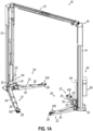
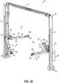
- FIGS. 1A-1B show an illustrative frame-engaging vehicle lift, a two-post lift (10), that can be used to raise a vehicle, allow access to the underside of the vehicle, and allow wheels and tires of the vehicle to be removed or serviced.
- the current frame-engaging vehicle lift is a two-post lift (10)
- any other suitable frame-engaging vehicle lift may be used as would be apparent to one skilled in the art in view of the teachings herein.
- the frame-engaging vehicle lift may be a scissor-lift assembly, a four-post lift, an in-ground lift such as Smartlift ® manufactured and sold by Vehicle Service Group, LLC, or one or more portable lifts, etc.
- Two-post lift (10) includes a pair of lift posts (12, 14), a crossbar (15) extending between lift posts (12, 14), a pair of lifting carriages (20) operatively coupled to a respective lift post (12, 14), a control assembly (50), and a drive assembly (60).
- Lift posts (12, 14) extend from a floor (16) to an elevated portion (18), while a crossbar (15) extends between lift posts (12, 14) at elevated portion (18).
- Lifting carriages (20) are configured to synchronously actuate along a path defined by respective lift posts (12, 14) between a lowered position (as shown in FIG. 1A ) and a raised position (as shown in FIG. 1B ). Lifting carriages (20) may also selectively lock into place relative to respective lift posts (12, 14) such that lifting carriages (20) may be prevented from inadvertently lowering once reaching a desired height. Therefore, lift posts (12, 14) may provide a mechanical path for respective lifting carriages (20) to actuate along. Any suitable components to promote synchronous actuation and locking of lifting carriages (20) relative to lift posts (12, 14) may be used as would be apparent to one skilled in the art in view of the teachings herein.
- lifting carriages (20) are configured to engage the frame of a vehicle such that as lifting carriages (20) actuate between the lowered position (as shown in FIG. 1A ) and the raised position (as shown in FIG. 1B ), the vehicle will also be lifted and lowered between corresponding lowered and raised positions.
- Each lifting carriage (20) includes a base frame (30) and a pair of adjustable lifting arms (22) configured to be adjusted relative to their respective base frame (30) and relative to each other in order to suitably engage a vehicle frame.
- Base frames (30) suitably engage their respective lift post (12, 14) such that lifting carriages (20) may synchronously actuate along their path defined by lift posts (12, 14).
- Each lifting arm (22) includes a collar (24) and an adjustable body (26) that terminates in an adapter coupling end (28).
- Each collar (24) is pivotally coupled to base frame (30) of the respective carriage (20) about a pivot axis (PA) via a pivot pin (32). Therefore, collar (24), adjustable body (26), and adapter coupling end (28) may be pivoted about pivot axis (PA) together into various rotational positions relative to base frame (30).
- carriages (20) may have a pivot restraint mechanism to selectively fix each collar (24) into a desired rotational position relative to base frame (30) about pivot axis (PA). Therefore, lifting arms (22) may be pivoted and restrained into a desired rotational position relative to base frame (30) of carriage (20) in order to suitably align with specific vehicle lift points.
- Adjustable body (26) may actuate along a linear path defined by a respective collar (24) and into various longitudinal positions relative to collar (24).
- carriages (20) may have a linear locking mechanism to selectively fix the longitudinal position of adjustable body (26) relative to the respective collar (24). Therefore, adjustable body (26) may be actuated and locked into a desired longitudinal position relative to the respective collar (24) in order to suitably align with specific vehicle lift points.
- Adjustable body (26) and adapter coupling end (28) may be fixed relative to each other, although this is merely optional.
- Adapter coupling end (28) is configured to selectively couple with various arm adapters, such as arm adapter (100).
- Arm adapters (100) may be configured to suitably engage vehicle frames such that lifting carriages (20) may lift vehicles in accordance with the description herein.
- Two-post lift (10) may be connected to a power supply (not pictured) to provide power to various components of two-post lift (10), such as control assembly (50) and drive assembly (60).
- Control assembly (50) is operatively connected to drive assembly (60) such that an operator may utilize control assembly (50) to selectively activate drive assembly (60) in accordance with the teachings herein.
- Control assembly (50) may include any suitable components, such as a processor, logic control, etc., as would be apparent to one skilled in the art in view of the teachings herein. Additionally, control assembly (50) may include any suitable number of user input features in order to utilize two-post lift (10) in accordance with the description herein.
- control assembly (50) is physically attached to the rest of two-post lift (10), but this is merely optional. In some embodiments, control assembly (50) may be detached from the rest of two-post lift (10) such that control assembly (50) is in wired/wireless communication with other suitable components of two-post lift (10). In some embodiments, control assembly (50) is incorporated into a fixed control panel, a wired or wireless pendant, a smart phone, a tablet, or a control station such as a desktop or laptop.
- Drive assembly (60) is configured to raise and lower carriages (20) in accordance with the description herein by producing mechanical energy that is translated to a lifting motion of the carriages (20) through a mechanical linkage, hydraulic system, screw mechanism, other systems, or any combination thereof as will be apparent to one skilled in the art in view of the teachings herein. Therefore, drive assembly (60) may include any number of suitable components to raise and lower carriages (20) in accordance with the description herein.
- the operator may place a vehicle between lift posts (12, 14) with carriages (20) at or near the lowered position.
- the operator may suitably align carriages (20) with a frame of the vehicle by rotating and extending/retracting adjustable lift arms (22).
- the operator may utilize control assembly (50) in order to activate drive assembly (60) to synchronously raise carriages (20) such that arm adapters (100) engage the frame and thereby lift the vehicle.
- control assembly (50) to instruct drive assembly (60) to stop raising carriages (20).
- a vertical lockout assembly may be used to ensure carriages (20) remain locked at the desired height along lift posts (12, 14).
- control assembly (50) When the operator desires to lower the vehicle, the operator may use control assembly (50) to activate drive assembly (60) to synchronously lower carriages (20) such the vehicle is lowered to the ground and arm adapters (100) disengage the frame of the vehicle. With arm adapters (100) disengaged from the frame of the vehicle, the vehicle may be removed from the lifting area, and another vehicle may be subsequently moved into the lifting area for service.
- adjustable lift arms (22) may actuate to either extend or retract adapter (100) relative to pivot pin (32).
- actuation between collar (24) and adjustable body (26) allows adapter (100) to transition between a fully extended configuration (when adapter (100) is the furthest away from pivot pin (32)) and a fully retracted configuration (when adapter (100) is the closest to pivot pin (32)).
- Adjustable body (26) and collar (24) have a telescoping relationship, which allows adjustable body (26) to extend and retract relative to collar (24).
- Adjustable lift arms (22) may include more than one telescoping member to further increase the fully extended range by offering a multi-stage extension (e.g., a three-stage extension).
- adjustable lift arm In order to provide for easier movement between telescoping features of adjustable lift arm (22), it may be desirable to reduce the material used to form lift arm (22). Such reduction of material, in turn, reduces the weight of telescoping features, reducing the frictional braking force that must be overcome to adjust such telescoping features, which may provide easier movement of telescoping features by a technician.
- adapter (100) may be desirable to lower adapter (100) as close to floor (16) as possible (i.e., a low-profile configuration) in order to accommodate low clearance vehicles.
- a low-profile configuration For example, electric vehicles (EVs) may require adapter (100) to reach a low-profile configuration in order to suitably access the underside of such an EV.
- lift arm (22) e.g., adjustable body (26)
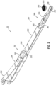
- FIGS. 2 and 7A-8D show an adjustable lifting arm (222) that may be substantially similar to adjustable lifting arm (22) described above, with differences elaborated below. Therefore, adjustable lifting arm (222) may be readily incorporated into two-post lift (10) to replace adjustable lifting arm (22) described above. As will be described in greater detail below, adjustable lifting arm (222) may be formed with a reduced amount of material compared to previous lifting arms, which may provide for easier movement of adjustable lifting arm (222) in accordance with the description herein. Additionally, as will be described in greater detail below, lifting arm (222) includes various features that allow for adjustable low-profile configurations while also (A) inhibiting telescoping features from extending past a predetermined extended configuration, and (B) allowing for a shorter fully retracted, yet operational, length.
- Adjustable lifting arm (222) includes a collar (224), an adjustable body (226), an adapter coupling arm (270), and an adapter (200).
- Collar (224) includes a proximal portion (250) and a distal portion (251).
- adjustable body (226) includes its own proximal portion (260) and distal portion (261)
- adapter coupling arm (270) also includes its own proximal portion (280) and distal portion (282).
- Collar (224), adjustable body (226), and adapter coupling arm (270) are slidably coupled together in a telescoping relationship.
- adjustable body (226) is slidably contained within a telescoping channel (255) defined by collar (224), while adapter coupling arm (270) is slidably contained within a telescoping channel (267) defined by adjustable body (226).
- FIG. 3A illustrates a top perspective view of adapter coupling arm (270).
- Adapter coupling arm (270) includes an adapter coupling end (228) located at distal portion (282), a proximal top surface (284), a distal top surface (286), a lower surface (288) (see FIG. 3B ), and a tapered body (272) extending between and attached to top surfaces (284, 286).
- Adapter coupling arm (270) defines a longitudinally extending groove (274) that terminates proximally in a groove end (276).
- a portion of tapered body (272) and proximal top surface (284) together define longitudinally extending groove (274).
- Tapered body (272) reduces in cross-sectional area toward adapter coupling end (228). Reducing cross-sectional area may reduce both weight and cost of adapter coupling arm (270). Tapered body (272) may also provide for better maneuverability (e.g., due to the reduction of weight) while positioning adjustable lifting arm (222) under a lift spot of a vehicle. Additionally, as will be described in greater detail below, tapered body (272) provides a vertical offset distance (d) (see FIG. 9 ) between top surfaces (284, 286), which may reduce the vertical profile of adapter (200), thereby providing a low-profile configuration, during exemplary use in accordance with the description herein. Adapter coupling end (228) is flared out or bulbous relative to a narrow portion of tapered body (272) such that an operator may easily grab adapter coupling end (228) when extending adjustable lifting arm (222).
- Groove (274) may be a channel or slit within a portion of adapter coupling arm (270) such that the groove (274) forms a valley within the top of adapter coupling arm (270). Due to the tapered nature of tapered body (272), the depth of groove (274) increases from its distal end associated with tapered body (272) toward its proximal end associated with groove end (276) and proximal top surface (284). Groove (274) may include a bottom surface that is substantially parallel with a bottom surface of adapter coupling arm (270).
- groove (274) may include a bottom surface that is sloped upward toward the top surface (284) in the proximal direction relative to a bottom surface of adapter coupling arm (270) such that the portion of bottom surface located adjacent to groove end (276) is vertically higher compared to the portion of bottom surface located adjacent to distal top surface (286).
- Such a sloped bottom surface of groove (274) may be used to slow extension as coupling arm (270) approaches a distal-most position via engagement between the bottom surface of groove (274) and groove stop (264) (see FIGS. 5A-5B and 7A ).
- the side walls of groove (274) may include sloped surfaces such that groove (274) is narrower nearer the proximal end than nearer its distal end.
- Such sloped side walls may be used to slow extension as coupling arm (270) approaches a distal-most position via engagement between the side surfaces of groove (274) and groove stop (264) (see FIGS. 5A-5B and 7A ).
- groove (274) terminates longitudinally into groove end (276).
- groove end (276) forms a shoulder surface that engages a groove stop (264) (see FIGS. 5A-5B and 7A ) of adjustable body (226) to prevent overextension of adapter coupling arm (270) relative to adjustable body (226).
- proximal portion (280) of adapter coupling arm (270) defines a cutout (278).
- Cutout (278) is positioned along a bottom surface of adapter coupling arm (270) to thus form a "U" shaped channel in adapter coupling arm (270).
- Cutout (278) extends from an opposing end of adapter coupling end (228) towards adapter coupling end (228).
- Cutout (278) may follow an external side contour of adapter coupling arm (270) such that there is sufficient lateral sidewall to support adapter coupling arm (270) to inhibit an undesirable amount of lateral and/or vertical flex.
- Portions of adapter coupling arm (270) defining cutout (278) are structurally robust to suitably support a vehicle during exemplary use in accordance with the description herein.
- cutout (278) may be positioned beneath groove (274) such that an opening is formed between groove (274) and cutout (278).
- material may remain between cutout (278) and groove (275) to thereby keep them as separate cavities.
- Cutout (278) may have any suitable geometry as would be apparent to one skilled in the art in view of the teachings herein.
- Cutout (278) may reduce the overall weight of adapter coupling arm (270) without substantially reducing the load strength. The reduction of the overall weight of adapter coupling arm (270) may provide easier telescoping movement of adapter coupling arm (270) relative to the adjustable body (226). Bottom surfaces of adapter coupling arm (270) that are lateral to cutout (278) may remain along the same plane as the remaining bottom surface (288) of adapter coupling arm (270). As shown, adapter coupling arm (270) may include angled edges (290) extending into cutout (278). Adapter coupling arm (270) may be produced through a forging or a mold casting process.
- FIG. 3C shows adapter coupling end (228) having a key recess (277) and opening (279) dimensioned to receive select portions of adapter (200).
- Adapter coupling end (228) includes a recessed upwardly presented surface (276) that partially defines key recess (277).
- Key recess (277) is configured to accept adapter collar (203) of adapter (200) and also inhibit rotation of adapter collar (203) when inserted into opening (279).
- Key recess (277) includes one or more keys such that key recess (277) is capable of locking adapter collar (203) in more than one rotational position via engagement between keys and engagement surfaces (207) (see FIG. 4 ) of adapter collar (203).
- Upwardly presented surface (276) is configured to engage a downwardly presented shoulder (205) of adapter (200) in order to transmit the load of a supported vehicle from adapter (200) onto adapter coupling arm (270) in a low-profile configuration.
- Opening (279) may be in the form of a through-hole or a blind-hole and can be configured to axially align adapter collar (203) with adapter coupling end (228). Opening (279) may also be in a shape other than a circle such that adapter collar (203) is rotationally restricted once inserted into opening (279).
- adapter (200) may be vertically adjustable by way of a suitable vertical adjustment mechanism that would be obvious to one of ordinary skill in the art in view of the teachings herein.
- a suitable screw mechanism may be used to readily adjust the vertical position of adapter (200) relative to adapter coupling end (228).
- a vertical adjustment mechanism include a stepped adjustment, a cam adjustment, a plurality of replaceable adapters with varying heights, a vertically telescoping adapter, etc.
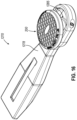
- FIG. 4 shows a bottom side perspective view of adapter (200) having the adapter collar (203), a shaft (204), a support surface (206), and a contact pad (208).
- Adapter collar (203) protrudes downward from support surface (206) and is shaped and sized to fit within key recess (277) to rotationally inhibit adapter collar (203) and adapter (200) via engagement between engagement surfaces (207) and keys of key recess (277).
- Adapter collar (203) includes downwardly presented shoulder (205) which is configured to engage upwardly presented surface (276) of adapter coupling end (228) in a low-profile configuration, to thereby transfer the load of a supported vehicle from adapter (200) onto adapter coupling arm (270).
- adapter (200) while adapter (200) is in the low-profile configuration relative to adapter coupling arm (270), suitable portions of contact pad (208) (e.g., an outer perimeter of contact pad (208)) are configured to be directly adjacent to (e.g., come into contact with) pad engagement surfaces (263) of second notch (262) of adjustable body (226) (see FIG. 8B ).
- adapter collar (203) is dimensioned to fit adjacent to second notch (262) of adjustable body (226) while adapter (200) is in a raised configuration relative to adapter coupling arm (270) and adapter coupling arm (270) is completely housed within telescoping channel (267) of adjustable body (226) (see FIG. 8C ).
- shaft (204) extends downward beyond support surface (206) and adapter collar (203) to act as a guide for adapter (200) when adapter (200) is inserted into opening (279) of adapter coupling end (228).
- Shaft (204) may be circular in shape or may be non-circular such that it may inhibit rotation of adapter (200) when inside opening (279).
- Shaft (204) may be either longer or shorter than opening (279) is deep and may include a rounded tip to aid in the positioning of shaft (204) within opening (279).
- Support surface (206) extends radially beyond adapter collar (203) and shaft (204). As mentioned above, in the low-profile configuration, downwardly presented shoulder (205) of adapter (200) and upwardly present surface (276) of adapter coupling end (228) are engaged with each other in order to transmit the load of a lifted vehicle from adapter (200) onto adapter coupling arm (270).
- Adapter collar (203), shaft (204), and support surface (206) may be formed of a metal such as steel, or any suitable material as would be apparent to one skilled in the art in view of the teachings herein.
- Contact pad (208) is positioned on top of support surface (206).
- Contact pad (208) includes a contact surface (202) configured to engage one or more lifting points of a vehicle.
- Contact pad (208) may be made using rubber or plastic and may be the point of contact between the vehicle and the remaining portions of adjustable lifting arm (222).
- Contact pad (208) may be modular and different contact pads (208) may come in differing shapes and sizes depending on the application.
- FIG. 5A shows a perspective view of adjustable body (226).
- Adjustable body (226) may be in the form of a hollow channel or tube defining telescoping channel (267) and includes second notch (262) located at distal portion (261).
- Second notch (262) may include a channel or opening on an upper portion (268) of adjustable body (226) and may be semicircular in shape.
- second notch (262) is sized and shaped to accommodate adapter (200) when adapter coupling arm (270) is retracted within adjustable body (226).
- second notch (262) includes pad engagement surfaces (263) configured to engage pad (208) in the retracted, low-profile configuration (see FIG. 8B ).
- Support surface (206) of adapter (200) may include a larger diameter than second notch (262) such that support surface (206) rests on top of second notch (262) when adapter coupling arm (270) is in the retracted configuration (see FIG. 8C ). As shown between FIGS. 8B-8C , should adapter (200) be lifted from adapter coupling arm (270) to rest on top of adjustable body (226), shaft (204) may still be long enough to engage opening (279) for continued alignment.
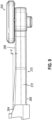
- FIG. 5B shows a front perspective view of adjustable body (226).
- Adjustable body (226) includes a groove stop (264), also referred to as an abutment, positioned within adjustable body (226).
- Groove stop (264) is a protrusion from an upper portion (268) of adjustable body (226) and projects downwards into a telescoping channel (267) of adjustable body (226).
- Groove stop (264) is dimensioned to slidably fit within groove (274) of adapter coupling arm (270) and may have a profile matching that of groove (274).
- Groove stop (264) is configured to contact groove end (276) of groove (274) when adapter coupling arm (270) is extended away from adjustable body (226) in a fully extended configuration.
- groove end (276) contacting groove stop (264) may thereby define a fully extended configuration of adapter coupling arm (270) relative to adjustable body (226).
- Groove stop (264) contacts groove end (276) such that further extension of adapter coupling arm (270) relative to adjustable body (226) may be inhibited or prevented.
- groove stop (264) and groove (274) interact with each other to prevent overextension of adapter coupling arm (270) relative to adjustable body (226). It should be understood that since groove stop (264) is housed within telescoping channel (267), this may reduce the overall vertical profile of adjustable body (226) and lifting arm (222) as compared to groove stop (264) being located on an exterior surface of adjustable body (226). Therefore, the location of groove stop (264) within telescoping channel (267) may allow adapter (200) to be lowered closer to floor (16) during exemplary use as compared to being on an exterior surface of adjustable body (226).
- Groove stop (264) may be formed, welded, or screwed into the upper portion (268) of adjustable body (226). Groove stop (264) may be selectively removed from adjustable body (226) to thus allow adapter coupling arm (270) to be removed from adjustable body (226) and can be positioned such that groove stop (264) does not project beyond the outside of adjustable body (226) and contact collar (224). Groove stop (264) may alternatively be securely fixed such that adapter coupling arm (270) is inserted into adjustable body (226) through an open end (266) opposite second notch (262).
- Adjustable body (226) may be welded to the remaining portions of adjustable body (226). Adjustable body (226) may also be largely extruded as a single piece and groove stop (264) may be added after.
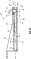
- FIG. 10 shows an alternative adjustable body (326) formed from an extrusion process. Therefore, adjustable body (336) is substantially similar to adjustable body (226) described above, with differences elaborated herein. Upper portion (368) and opposing lower portion (369) may be thicker than the lateral sidewalls (370) of adjustable body (326). Therefore, lateral sidewalls (370) may be thinner than the lateral sidewalls of adjustable body (226).
- Making lateral sidewalls (370) thinner than upper and lower portions (368, 369) may reduce the weight of adjustable body (326), which may provide easier telescoping movement of adjustable body (326). Additionally, making lateral sidewalls (370) thinner than upper and lower portions (368, 369) may reduce the amount of material needed to form adjustable body (326) compared to adjustable body (226) described herein.
- adjustable body (226) includes a stop contact (265) on lower portion (269).
- Stop contact (265) may extend outside of lower portion (269) and in a downward direction. Stop contact (265) may be selectively coupled to lower portion (269).
- stop contact (265) may include a screw which is threaded into an opening in lower portion (269) where a head of the screw projects downward from lower portion (269). Stop contact (265) may or may not extend into the channel of adjustable body (226).
- FIG. 6 shows a perspective view of collar (224) having a support surface (254), a stop (256), and an opening (258).
- Support surface (254) is positioned near edge (253) of collar (224) located at distal end (251) of collar (224).
- Support surface (254) is configured to vertically support a portion of adjustable body (226).
- Support surface (254) may be comprised of a low friction material and may also be suitable for applications of high wear.
- Support surface (254) supports adjustable body (226) such that adjustable body (226) does not contact lower portion (257) of collar (224). Therefore, support surface (254) may reduce the frictional braking force between engaging surface of collar (224) and adjustable body (226), which may also enable easier telescoping movement of adjustable body (326).
- collar (224) may have a welded-on upper portion.
- collar (224) may be extruded largely as a single piece.
- FIG. 11 shows an alternative collar (324) formed from an extrusion process. Therefore, collar (324) is substantially similar to collar (224) described above, with differences elaborated herein.
- Upper portion (328) and opposing lower portion (330) may be thicker than the lateral sidewalls (332) of collar (324). Therefore, lateral sidewalls (332) may be thinner than the lateral sidewalls of collar (224).Making lateral sidewalls (322) thinner than upper and lower portions (328, 330) may reduce the weight of collar (324), which may improve the movability of collar (324). Additionally, making lateral sidewalls (332) thinner than upper and lower portions (328, 330) may reduce the amount of material needed to form collar (324) compared to collar (224) described herein.
- stop (256) is positioned away from edge (253) relative to support surface (254) such that there is a distance between support surface (254) and stop (256).
- Stop (256) may be secured to lower portion (257) and inside of collar (224) and configured to contact stop contact (265) of adjustable body (226) when adjustable body is in an extended configuration relative to collar (224). Stop (256) may thereby define an extended configuration of adjustable body (226) as being when stop contact (265) contacts stop (256). Stop (256) may prevent adjustable body (226) from over-extending by interfering with stop contact (265).
- stop (256) is housed within telescoping channel (255), this may reduce the overall vertical profile of collar (224) and lifting arm (222) as compared to stop (256) being located on an exterior surface of collar (224). Therefore, the location of stop (256) within telescoping channel (255) may allow adapter (200) to be lowered closer to floor (16) during exemplary use as compared to being on an exterior surface of collar (224). In other words, positioning stop (256) inside of collar (224) may decrease the overall vertical profile of adjustable lifting arm (222) to thereby decrease a distance between contact surface (202) of adapter (200) and floor.
- Stop (256) and/or support surface (254) may contain felt wipers that store lubricant to reduce wear and promote smooth movement between collar (224) and adjustable body (226). Stop (256) and or support surface (254) may include a bearing or a set of bearings that promote smooth movement between collar (224) and adjustable body (226).
- stop (256) and support surface (254) are two different pieces spaced apart from each other, stop (256) and support surface (254) may have any suitable spatial relationship as would be apparent to one skilled in the art in view of the teachings herein.
- stop (256) and support surface (254) may be a single piece of material.
- stop (256) and support surface (254) may abut against each other in an end-to-end fashion.
- collar (224) defines stop contact opening (258).
- adjustable body (226) may be inserted into collar (224) to where stop contact opening (258) axially aligns with an attachment point for stop contact (265).
- stop contact (265) may be passed through stop contact opening (258) and attached to adjustable body (226).
- Stop contact opening (258) may be positioned further from edge (253) than stop (256).
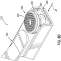
- FIGS. 7A-8D show a method of using the adjustable lifting arm (222) and transitioning between a fully extended configuration ( FIGS. 7A and 8A ), a partially retracted configuration ( FIGS. 7B and 8B-8C ), and a fully retracted configuration ( FIGS. 7C and 8D ).
- FIG. 7A shows adjustable lifting arm (222) in the fully extended configuration with adjustable body (226) extended relative to collar (224) and adapter coupling arm (270) extended relative to adjustable body (226).
- stop contact (265) may be in contact with stop (256)
- groove end (276) may be in contact with groove stop (264)
- support surface (206) may be in contact with a top surface of adapter coupling arm (270).
- adapter coupling arm (270) may maintain the low-profile configuration while adapter coupling arm (270) is between any location shown between FIGS. 7A-7B and 8A-8B .
- a user may further customize the overall length of lifting arm (222) by also telescoping adjustable body (226) within collar (224), thereby allowing adapter (200) to reach various lengths while still maintaining the low-profile configuration.
- adapter coupling arm (270) may move adapter (200) upwards within adapter coupling end (228) and retract adapter coupling arm (270) such that pad (208) no longer abuts against surfaces (263) and such that contact pad (208) rests above second notch (262).
- a retracting force may be applied to adapter coupling arm (270), adapter (200), and/or adjustable body (226) towards collar (224).
- adjustable body (226) When sliding adjustable body (226) towards collar (224), adjustable body (226) may be partially supported by support surface (254), and stop contact (265) may cease contact with stop (256).
- stop contact (265) may cease contact with stop (256).
- edge (253) of collar (224) may be flush with or extend beyond a similar outside edge of adjustable body (226).
- the entirety of pad (208) is located proximally to edge (253).
- Notch (252) also houses and/or engages a portion of the periphery of pad (208) in the fully retracted position. Therefore, lifting arm (222) allows adjustable body (226), adapter coupling arm (270), and adapter (200) to be located proximally to edge (253) in the fully retracted position. This nesting configuration allows vehicle engagement pad (208) to be located proximally to edge (253) of collar (224) when adjustable body (226) is in the fully retracted position, which may allow adjustable lifting arm (222) to access a wider range of vehicle lifting points compared to lifting arms with vehicle engagement pads that are located distally relative to collar (224) when adjustable body (226) is in that position. Additionally, adapter (200) is configured to suitably engage a vehicle in the fully retracted position.
- edge (253) of collar (224) is located distally beyond the furthest edge of adapter coupling arm (270) such that adapter coupling arm (270) is fully inside adjustable body (226) and collar (224).
- second notch (262) may rotationally orient or inhibit adapter (200) once adapter (200) is placed within second notch (262) as shown in FIG. 8C .
- first notch (252) of collar (224) may be sized and shaped such that contact pad (208) of adapter (200) may fit within first notch (252) without interference.
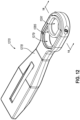
- FIG. 12 illustrates a top perspective view of an alternative adapter coupling arm (1270).
- Adapter coupling arm (1270) may be substantially similar and may function substantially similarly to adapter coupling arm (270) except for the following differences. Therefore, it should be understood that adapter coupling arm (1270) may be readily incorporated into adjustable lifting arm (222) in replacement of adapter coupling arm (270).
- Adapter coupling arm (1270) includes an adapter coupling arm body (1278) and a sleeve (1285) slidably coupled to adapter coupling arm body (1278).
- Adapter coupling arm body (1278) defines an elongate opening (1279) capturing sleeve (1285) slidable therein.
- FIG. 13 illustrates a top perspective exploded view of adapter coupling arm (1270) with sleeve (1285) including an upper flange (1287), a lower flange (1289), and an opening (1291).
- Upper and lower flanges (1287, 1289) vertically contain sleeve (1285) within elongate opening (1279) while allowing sleeve (1285) to slide along a path defined by elongate opening (1279).
- Opening (1291) of sleeve (1285) is sized to fit adapter collar (203) and shaft (204) of adapter (200) such that adapter (200) is supported by adapter coupling arm (1270) while still being able to slide with sleeve (1285).
- adapter (200) may selectively couple with sleeve (1285) via opening (1291) such that sleeve (1285) and adapter (200) are configured to actuate relative to adapter coupling arm body (1278) along the path defined by elongate opening (1279).
- adapter coupling arm body (1278) may be a unitary component. In other instances, as shown in FIG. 13 , adapter coupling arm body (1278) may be assembled from multiple components in order to slidably capture sleeve (1285), or it may be assembled as shown. Adapter (200) and adapter coupling arm (1270) may be capable of achieving any of the configurations shown in FIGS. 7A-8D . It should be understood that, in some instances, adapter coupling arm (1270) and adapter (200) may be fully retracted within adjustable body (226) regardless of the position of sleeve (1285) within elongate opening (1279).
- FIG. 14 illustrates a cross-sectional view of adapter coupling arm (1270) taken along line 14-14 and with adapter (200) included. As shown, upper and lower flanges (1287, 1289) vertically capture sleeve (1285) within elongate opening (1279). Support surface (206) of adapter (200) may also contact a top surface of sleeve (1285) to vertically support adapter (200).
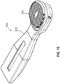
- FIGS. 15-16 illustrate sliding adapter (200) from a distal position, as shown in FIG. 15 , to a proximal position, as shown in FIG. 16 , within elongate opening (1279).
- An operator may slide adapter (200) and sleeve (1285) together by applying either a distal or proximal force on adapter (200).
- Adapter (200) and adapter coupling arm (127) are capable of lifting a vehicle while the adapter (200) is in the proximal or distal position of elongate opening (1279), or any other position therebetween. Therefore, it should be understood that an operator may use adapter coupling arm (1270) to make minor adjustments to the position of adapter (200) relative to adapter coupling arm body (1278).
- Sliding adapter (200) relative to adapter coupling arm (1270) therefore defines adjustable lifting arm (22) as a four-stage arm where four components are independently translatable relative to each other.
- a vehicle engagement assembly attached to a vehicle lift wherein the vehicle lift is configured to actuate the engagement assembly between a lowered position and a raised position
- the vehicle engagement assembly comprises: (a) a first arm comprising a first notch and having a distalmost edge, (b) a second arm configured to transition between a first extended configuration and a first retracted configuration relative to the first arm, (c) an adapter coupling arm comprising a coupling portion, wherein the adapter coupling arm is configured to translate within the second arm between a second extended configuration and a second retracted configuration, and (d) an adapter configured to couple with the coupling portion, wherein the adapter is configured to fit adjacent to the first notch such that the adapter is proximal to the distalmost edge when both the second arm is in the first retracted configuration and the adapter coupling arm is in the second retracted configuration.
- the adapter includes a vehicle contact surface, wherein the vehicle contact surface is configured to be positioned above the first notch when the adapter is coupled with the coupling portion, the second arm is in the first retracted configuration, and the adapter coupling arm is in the second retracted configuration.
- the adapter includes a first cross-section sized to fit within the first notch and a second cross-section sized to fit with a second notch of the second arm.
- the adapter is configured to be positioned at a first height when the adapter coupling arm is in the second retracted position and at a second height when the adapter coupling arm is in the second extended position, wherein the first height is higher than the second height.
- the adapter coupling arm includes a groove having a groove end
- the second arm includes an abutment, wherein the abutment is configured to traverse the groove and contact the groove end to thereby prevent the adapter coupling arm from extending beyond the second extended configuration.
- the adapter coupling arm includes a lower cutout such that a portion of the adapter coupling arm is a U channel.
- the first arm includes a support and a channel having a lower portion, wherein the second arm is positioned within the channel, wherein the support is positioned on the lower portion and is configured to contact the second arm to thereby lift the second arm away from the lower portion.
- the first arm includes a stop, wherein the stop is configured to contact the second arm when the second arm is in the first extended configuration.
- Example 12 The vehicle engagement assembly of Example 12, the second arm including a stop contact, wherein the stop contact is configured to contact the stop when in the first extended configuration to thereby prevent the second arm from extending beyond the first extended configuration.
- Example 13 The vehicle engagement assembly of Example 13, the first arm including an opening configured to allow the stop contact to pass through the opening and to attach to the second arm while the second arm is in a channel of the first arm.
- the second arm includes upper, lower, and lateral sidewalls, wherein the upper and lower sidewalls are thicker than the lateral sidewalls.
- a vehicle engagement assembly attached to a vehicle lift wherein the vehicle lift is configured to actuate the engagement assembly between a lowered position and a raised position
- the vehicle engagement assembly comprises: (a) a first arm defining a channel and a stop, the stop being positioned within the channel, the channel including an opening, (b) a second arm including a stop contact, wherein the second arm is configured to transition between a first extended configuration and a first retracted configuration about the first arm, wherein the stop contact is configured to traverse through the opening to thereby selectively couple with the second arm and, once coupled with the second arm, to contact the stop to thereby define the first extended configuration and to prevent the second arm from extending beyond the first extended configuration, (c) an adapter coupling arm comprising a coupling portion and configured to transition between a second extended configuration and a second retracted configuration relative to the second arm, and (d) an adapter configured to couple with the coupling portion and to contact a vehicle.
- Example 16 The vehicle engagement assembly of Example 16, wherein the second arm includes a notch, wherein the adapter is configured to fit within the notch when the adapter coupling arm is in the second retracted configuration.
- the first arm further includes a support, wherein the second arm is positioned within the channel, wherein the support is positioned on the lower surface and is configured to contact the second arm to thereby lift the second arm away from the lower surface, wherein the support and the stop are separated by a distance.
- a method of using a vehicle engagement assembly attached to a vehicle lift comprising: a first arm comprising a first notch, a second arm comprising a second notch, and an adapter coupling arm comprising an adapter, wherein the second arm is translatable relative to the first arm, and the adapter coupling arm is translatable relative to the second arm, the method comprising translating the second arm relative to the first arm, translating the adapter coupling arm relative to the second arm, and nesting the adapter into the first notch and the second notch.
- Example 19 The method of Example 19, further comprising extending the adapter coupling arm about the second arm to thereby unnest the adapter from the second notch, and, once unnested, lowering the adapter onto the adapter coupling arm.
Landscapes
- Life Sciences & Earth Sciences (AREA)
- Engineering & Computer Science (AREA)
- Geology (AREA)
- Mechanical Engineering (AREA)
- Structural Engineering (AREA)
- Vehicle Body Suspensions (AREA)
Applications Claiming Priority (1)
| Application Number | Priority Date | Filing Date | Title |
|---|---|---|---|
| US202363462752P | 2023-04-28 | 2023-04-28 |
Publications (1)
| Publication Number | Publication Date |
|---|---|
| EP4455074A1 true EP4455074A1 (de) | 2024-10-30 |
Family
ID=90924187
Family Applications (1)
| Application Number | Title | Priority Date | Filing Date |
|---|---|---|---|
| EP24172869.0A Pending EP4455074A1 (de) | 2023-04-28 | 2024-04-26 | Verschachtelter hebearm mit integrierten anschlägen |
Country Status (1)
| Country | Link |
|---|---|
| EP (1) | EP4455074A1 (de) |
Citations (5)
| Publication number | Priority date | Publication date | Assignee | Title |
|---|---|---|---|---|
| JP2002128481A (ja) * | 2000-10-20 | 2002-05-09 | Yasui:Kk | 車両整備用リフトの車体支持アーム |
| JP2005320173A (ja) * | 2005-07-19 | 2005-11-17 | Sugiyasu Corp | リフト装置 |
| EP2016017B1 (de) * | 2006-05-04 | 2010-03-24 | MAHA Maschinenbau Haldenwang GmbH & Co. KG | Tragarm für eine hebebühne |
| CN114763246A (zh) * | 2021-01-12 | 2022-07-19 | 汽车服务集团有限责任公司 | 用于汽车升降机的自动适配器定位 |
| EP4043384A1 (de) * | 2021-02-12 | 2022-08-17 | Vehicle Service Group, LLC | Konfigurierbarer innenarmadapter mit niedrigem profil für fahrzeugheber |
-
2024
- 2024-04-26 EP EP24172869.0A patent/EP4455074A1/de active Pending
Patent Citations (5)
| Publication number | Priority date | Publication date | Assignee | Title |
|---|---|---|---|---|
| JP2002128481A (ja) * | 2000-10-20 | 2002-05-09 | Yasui:Kk | 車両整備用リフトの車体支持アーム |
| JP2005320173A (ja) * | 2005-07-19 | 2005-11-17 | Sugiyasu Corp | リフト装置 |
| EP2016017B1 (de) * | 2006-05-04 | 2010-03-24 | MAHA Maschinenbau Haldenwang GmbH & Co. KG | Tragarm für eine hebebühne |
| CN114763246A (zh) * | 2021-01-12 | 2022-07-19 | 汽车服务集团有限责任公司 | 用于汽车升降机的自动适配器定位 |
| EP4043384A1 (de) * | 2021-02-12 | 2022-08-17 | Vehicle Service Group, LLC | Konfigurierbarer innenarmadapter mit niedrigem profil für fahrzeugheber |
Similar Documents
| Publication | Publication Date | Title |
|---|---|---|
| US20240359957A1 (en) | Nesting lift arm with integrated stops | |
| US9550658B2 (en) | Inground superstructure and integrated third stage arm for vehicle lift | |
| EP4043384A1 (de) | Konfigurierbarer innenarmadapter mit niedrigem profil für fahrzeugheber | |
| KR101426072B1 (ko) | 이송대차 | |
| US10344907B2 (en) | Vehicle jack stand | |
| EP4139242B1 (de) | Zweipfosten-fahrzeugaufzug mit kompakten teleskoparmen | |
| US8714504B2 (en) | Arrangement for mounting a support base on a wall | |
| US9114966B2 (en) | Commercial lifting device-jack stand | |
| US12129158B2 (en) | Lift superstructure arm pin | |
| CN114684739A (zh) | 用于提升和降低车辆或负载的升降装置和升降平台 | |
| EP4455074A1 (de) | Verschachtelter hebearm mit integrierten anschlägen | |
| WO1987007190A1 (en) | Procedure in car body rectifying work and rectifying means arrangement | |
| US20240246796A1 (en) | Two post lift with reversible offset telescoping lift arms | |
| HK40114239A (en) | Nesting lift arm with integrated stops | |
| US12134549B2 (en) | Restraint spline for pivoting arm of vehicle lift | |
| US7464914B2 (en) | Robust consumer lifting device-power unit | |
| CN118851022A (zh) | 带有集成止动件的嵌套举升臂 | |
| US7150482B1 (en) | Slide-out system with rollers | |
| WO2010058191A1 (en) | A vehicle support assembly | |
| US20180057326A1 (en) | Load transferring and self-adjusting saddle system for floor jacks and jack stands apparatus and method | |
| US20210356072A1 (en) | Jack stand with interchangable support tubes | |
| CZ289007B6 (cs) | Zvedák vozu | |
| EP3403988B1 (de) | Trägeranordnung sowie fahrzeughebebühne mit trägeranordnung | |
| US7413165B2 (en) | Robust consumer lifting device-slide forward bridge | |
| EP3130322B1 (de) | Badehebevorrichtung |
Legal Events
| Date | Code | Title | Description |
|---|---|---|---|
| PUAI | Public reference made under article 153(3) epc to a published international application that has entered the european phase |
Free format text: ORIGINAL CODE: 0009012 |
|
| STAA | Information on the status of an ep patent application or granted ep patent |
Free format text: STATUS: THE APPLICATION HAS BEEN PUBLISHED |
|
| AK | Designated contracting states |
Kind code of ref document: A1 Designated state(s): AL AT BE BG CH CY CZ DE DK EE ES FI FR GB GR HR HU IE IS IT LI LT LU LV MC ME MK MT NL NO PL PT RO RS SE SI SK SM TR |
|
| STAA | Information on the status of an ep patent application or granted ep patent |
Free format text: STATUS: REQUEST FOR EXAMINATION WAS MADE |
|
| REG | Reference to a national code |
Ref country code: HK Ref legal event code: DE Ref document number: 40114239 Country of ref document: HK |
|
| 17P | Request for examination filed |
Effective date: 20250221 |