EP4043384A1 - Konfigurierbarer innenarmadapter mit niedrigem profil für fahrzeugheber - Google Patents
Konfigurierbarer innenarmadapter mit niedrigem profil für fahrzeugheber Download PDFInfo
- Publication number
- EP4043384A1 EP4043384A1 EP22156331.5A EP22156331A EP4043384A1 EP 4043384 A1 EP4043384 A1 EP 4043384A1 EP 22156331 A EP22156331 A EP 22156331A EP 4043384 A1 EP4043384 A1 EP 4043384A1
- Authority
- EP
- European Patent Office
- Prior art keywords
- vehicle
- adapter
- profile
- segment
- arm segment
- Prior art date
- Legal status (The legal status is an assumption and is not a legal conclusion. Google has not performed a legal analysis and makes no representation as to the accuracy of the status listed.)
- Withdrawn
Links
- 230000008878 coupling Effects 0.000 abstract description 3
- 238000010168 coupling process Methods 0.000 abstract description 3
- 238000005859 coupling reaction Methods 0.000 abstract description 3
- 230000000712 assembly Effects 0.000 description 12
- 238000000429 assembly Methods 0.000 description 12
- 239000000463 material Substances 0.000 description 3
- 238000004519 manufacturing process Methods 0.000 description 2
- 238000000034 method Methods 0.000 description 2
- 238000012986 modification Methods 0.000 description 2
- 230000004048 modification Effects 0.000 description 2
- 230000000284 resting effect Effects 0.000 description 2
- 238000010146 3D printing Methods 0.000 description 1
- 230000006978 adaptation Effects 0.000 description 1
- 239000000654 additive Substances 0.000 description 1
- 230000000996 additive effect Effects 0.000 description 1
- 238000004891 communication Methods 0.000 description 1
- 239000007788 liquid Substances 0.000 description 1
- 230000007246 mechanism Effects 0.000 description 1
Images


Classifications
-
- B—PERFORMING OPERATIONS; TRANSPORTING
- B66—HOISTING; LIFTING; HAULING
- B66F—HOISTING, LIFTING, HAULING OR PUSHING, NOT OTHERWISE PROVIDED FOR, e.g. DEVICES WHICH APPLY A LIFTING OR PUSHING FORCE DIRECTLY TO THE SURFACE OF A LOAD
- B66F7/00—Lifting frames, e.g. for lifting vehicles; Platform lifts
- B66F7/10—Lifting frames, e.g. for lifting vehicles; Platform lifts with platforms supported directly by jacks
- B66F7/16—Lifting frames, e.g. for lifting vehicles; Platform lifts with platforms supported directly by jacks by one or more hydraulic or pneumatic jacks
- B66F7/20—Lifting frames, e.g. for lifting vehicles; Platform lifts with platforms supported directly by jacks by one or more hydraulic or pneumatic jacks by several jacks with means for maintaining the platforms horizontal during movement
-
- B—PERFORMING OPERATIONS; TRANSPORTING
- B66—HOISTING; LIFTING; HAULING
- B66F—HOISTING, LIFTING, HAULING OR PUSHING, NOT OTHERWISE PROVIDED FOR, e.g. DEVICES WHICH APPLY A LIFTING OR PUSHING FORCE DIRECTLY TO THE SURFACE OF A LOAD
- B66F7/00—Lifting frames, e.g. for lifting vehicles; Platform lifts
- B66F7/28—Constructional details, e.g. end stops, pivoting supporting members, sliding runners adjustable to load dimensions
-
- B—PERFORMING OPERATIONS; TRANSPORTING
- B66—HOISTING; LIFTING; HAULING
- B66F—HOISTING, LIFTING, HAULING OR PUSHING, NOT OTHERWISE PROVIDED FOR, e.g. DEVICES WHICH APPLY A LIFTING OR PUSHING FORCE DIRECTLY TO THE SURFACE OF A LOAD
- B66F13/00—Common constructional features or accessories
-
- B—PERFORMING OPERATIONS; TRANSPORTING
- B66—HOISTING; LIFTING; HAULING
- B66F—HOISTING, LIFTING, HAULING OR PUSHING, NOT OTHERWISE PROVIDED FOR, e.g. DEVICES WHICH APPLY A LIFTING OR PUSHING FORCE DIRECTLY TO THE SURFACE OF A LOAD
- B66F3/00—Devices, e.g. jacks, adapted for uninterrupted lifting of loads
-
- B—PERFORMING OPERATIONS; TRANSPORTING
- B66—HOISTING; LIFTING; HAULING
- B66F—HOISTING, LIFTING, HAULING OR PUSHING, NOT OTHERWISE PROVIDED FOR, e.g. DEVICES WHICH APPLY A LIFTING OR PUSHING FORCE DIRECTLY TO THE SURFACE OF A LOAD
- B66F2700/00—Lifting apparatus
- B66F2700/12—Lifting platforms for vehicles or motorcycles or similar lifting apparatus
- B66F2700/126—Arrangements in which the platform is fixed to the upper end of a single or plural jacks
Definitions
- one or more posts are selectively retractable/extendable relative to the ground to raise/lower a vehicle relative to the ground.
- a single post may be positioned under the center of the vehicle.
- one post may be positioned at one side of the vehicle while another post is positioned at the opposite side of the vehicle.
- Such one or more posts may include superstructures that are capable of engaging the vehicle.
- Such superstructures may be mounted or otherwise coupled near the tops of the posts, such that the superstructure is raised/lowered relative to the ground as the one or more posts are retracted/extended relative to the ground.
- Such superstructures may include a yoke with one or more arms movably mounted thereto.
- a yoke may have a pair of arms that are movable relative to the yoke to selectively position the arms relative to the yoke.
- Each arm may have a member that is configured to engage the vehicle.
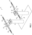
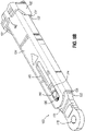
- FIGS. 1-2 illustrate an exemplary lift (10).
- Lift (10) of the present example comprises a housing (12) that extends beneath the level of ground (e.g., shop floor, etc.), a base plate (14) that is fixedly positioned relative to ground (e.g., level with shop floor, slightly elevated relative to shop floor, etc.), and a pair of posts (16) that extend or retract relative to the level of ground.
- FIG. 1 shows posts (16) retracted into the ground while FIG. 2 shows posts (16) extended relative to the ground.
- a superstructure (20) is fixedly mounted to the top of each post (16).
- Each superstructure (20) comprises a base portion (22), which is bolted or otherwise secured to the top of each post (16), and a yoke portion (24), which is integral with base portion (22).
- Each yoke portion (24) is associated with a respective pair of arm assemblies (130), which are pivotally secured to their corresponding yoke portion (24).
- each arm assembly (130) is joined to its corresponding yoke portion (24) by a pin (32).
- Each arm assembly (130) is rotatable about the longitudinal axis defined by its corresponding pin (32). While in the current example, superstructure (20) is used, any other suitable superstructure may be used as would be apparent to one skilled in the art in view of the teachings herein.
- arm assemblies (130) are configured to selectively attach to a respective vehicle engagement pad (40) via an adjustable adapter (160) ( see FIGS. 3A-3B ).
- Arm assemblies (130) and respective vehicle engagement pads (40) are configured to engage a vehicle and may be selectively positioned to engage a particular vehicle at particular lift points associated with the particular vehicle. For instance, with posts (16) retracted in the ground, arm assemblies (130) may be initially positioned outward as shown in FIG. 1 . The vehicle may then drive to a position over base plate (14) (e.g., such that the length of the vehicle is substantially centered over base plate (14)). The vehicle may need to drive over base portions (22) of superstructures (20) at this stage.
- the vehicle's wheels may ride directly over base portions (22).
- arm assemblies (130) may be rotated inwardly about pins (32) and suitably extend/retract in order to suitably align vehicle engagement pads (40) with lift point positions underneath the vehicle.
- posts (16) may be extended relative to the ground.
- vehicle engagement pads (40) being engaged with the vehicle at the selected lift points, and with arm assemblies (130) being engaged with pads (40) via adjustable adapter (160) ( see FIGS. 3A-3B ) and posts (16) via superstructures (20)
- such extension of posts (16) will raise the vehicle relative to the ground.
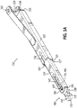
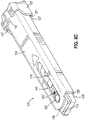
- FIG. 3A shows arm assembly (130) of the present example.
- Arm assembly (130) comprises a first segment (132) and a second segment (134).
- First segment (132) has an open distal end (131) and a proximal end (133).
- Second segment (134) has an open distal end (135) and a proximal end (not shown).
- first segment (132) and second segment (134) are elongated hollow metallic bodies.
- segments (132, 134) may take the form of any suitable material and any suitable shape as would be apparent to one skilled in the art in view of the teachings herein.
- First segment (132) of the present example includes a mounting portion (136).
- Mounting portion (136) provides a coupling with superstructure (20).
- Mounting portion (136) includes a pair of aligned openings (138), which are configured to receive pin (32) to provide pivoting coupling of a respective arm assembly (130) with superstructure (20).
- Second segment (134) telescopically extends from first segment (132) such that the effective length of arm assembly (130) may be selectively varied.
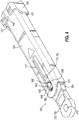
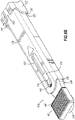
- first segment (132) defines a hollow interior (137) that is configured to receive second segment (134) such that second segment (134) may extend and retract relative to first segment (132) between an extended position (as shown in FIG. 3A ) and a retracted position (as shown in FIG. 3B ).
- Second segment (134) defines a hollow interior (139) in communication with open distal end (135). As will be described in greater detail below, hollow interior (139) is dimensioned to slidably receive adjustable adapter (160).
- Second segment (134) of arm assembly (130) further defines a slot (140).
- First segment (132) also defines a slot (142) that extends proximally from open distal end (131). Slot (142) is substantially aligned with slot (140).
- slots (140, 142) are suitably aligned such that when second segment (134) is adjusted toward the retracted position (as shown in FIG. 3B ), slot (142) may house a vehicle pad receptacle (162) such that vehicle pad (40) may be attached to vehicle pad receptable (162) in accordance with the description herein while receptable (162) is housed in slot (142) (as shown in FIG. 3B ).
- Arm assembly (130) may further be configured such that the longitudinal position of second segment (134) relative to first segment (132) may be selectively locked once second segment (134) has been translated relative to first segment (132) to a desired longitudinal position.
- a locking mechanism or feature is omitted.
- friction may substantially maintain an adjusted longitudinal positioning of second segment (134) relative to first segment (132).
- the mass and/or other properties of segments (132, 134) may permit a user to slide second segment (134) relative to first segment (132) to achieve an adjusted positioning; allow the user to then release second segment (134); and keep second segment (134) substantially in the adjusted position until the user again manipulates second segment (134) for further adjustment.
- arm assemblies (130) and vehicle engagement pads (40) may be pivoted about pins (32) until positioned under the vehicle.
- the length of arm assemblies (130) and the longitudinal position of engagement pad (40) relative to arm assemblies (130) may be adjusted in accordance with the description herein in order to suitably align vehicle engagement pads (40) with lift point positions of the vehicle.
- arm assemblies (130) and respective vehicle engagement pads (40) may not be able to suitably access the vehicle lift point positions.
- the vertical height of vehicle engagement pad (40) may extend above the maximum vertical height available for arm assembly (130) and vehicle engagement pad (40) to access the underside of a vehicle already resting on the ground.
- pad (40) may undesirably collide with the body of the vehicle.
- a "low-profile” extension plate would be welded to the distal end of an arm assembly (130) such that the extension plate extended distally past open distal end (135).
- a "low-profile” extension plate would be able to couple with and support a vehicle engagement pad (40) at a lower vertical height compared to inserting pad (40) through slot (140) of second segment (134). Therefore, while a "low-profile” extension plate may provide access to a vehicle having a lower vertical profile, the extension plate was not adjustable relative to second segment (134).
- this "low-profile” extension plate would permanently extend distally from open distal end (135) of second segment (142), the extension plate may act as an obstruction when either (A) second segment (134) needs to be closer to the fully retracted position (as shown in FIG. 3B ) or (B) pad (40) is coupled with second segment (134) via slot (140).
- a permanent "low-profile” extension plate may prevent an operator from suitably accessing the battery components of an EV while lifted.
- the permanent "low-profile” extension plate may block the battery cover plate from being removed while an EV is lifted or even block batteries from being removed from a lifted vehicle altogether.
- an arm adapter that allows an operator to couple vehicle engagement pad (40) via slot (140) or couple with a "low-profile” section that is distal relative to open distal end (135) of second segment (134), while also providing an adjustable capability such that the "low-profile” section may be entirely restricted within second segment (134) if needed.
- FIGS. 3A-10 show an exemplary adjustable adapter (160) that is configured to (A) adjustably couple with second segment (134) and (B) couple with a vehicle engagement pad (40) in a first profile configuration and a second, low-profile configuration. It should be understood that the first profile configuration and the low-profile configuration elevate engagement pad (40) to different vertical heights, thereby allowing pad (40) to access the underside of a variety of vehicles.
- adjustable adapter (160) is configured to translate relative to second segment (134) of arm assembly (130) such that the portion of adjustable adapter (160) forming the low-profile section may be entirely housed within second segment (134) if needed, while the portion of adjustable adapter (160) forming the low-profile section may also extend distally from open distal end (135) of second segment (134) if needed.
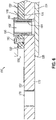
- adjustable adapter (160) includes a vehicle pad receptacle (162), a first body (172) having a low-profile platform (182), a second body (174) having a first profile platform (180), and a removable adapter containment member, such as containment screw (190).
- Vehicle pad receptacle (162) includes a sheath (164) and a collar (166) having a pair of flats (168).
- Vehicle pad receptacle (162) defines a hollow opening (165) extending from collar (166) through sheath (164).
- hollow opening (165) is dimensioned to selectively receive a post (44) of vehicle engagement pad (40) such that an engagement platform (42) of pad (40) rests above collar (166). Therefore, an operator may easily insert and remove post (44) into and out of hollow opening (165) of receptacle (162).
- adjustable adapter (162) is dimensioned to be moved relative to the rest of adjustable adapter (160) to rest on the either the first profile platform (180) or the low-profile platform (182), depending on which height profile an operator wishes to support pad (40). Therefore, adjustable adapter (160) is configured to easily couple with and support pad (40) in either the first profile platform (180) or the low-profile platform (182).
- First body (172) and second body (174) are suitably coupled with each other.
- First body (172) and second body (174) are dimensioned to slidably fit within hollow interior (139) of second segment (134) such that platforms (180, 182) face upward toward slot (140).
- first body (172) and second body (174) are configured to be inserted into second segment (134) at open distal end (135).
- First body (172) and second body (174) may be inserted into open distal end (135) in the orientation shown in FIG. 5 .
- first body (172) and second body (174) may be inserted into open distal end (135) in reverse fashion, as shown in FIG. 8C .
- First body (172) has a first thickness
- second body (174) has a second thickness.
- first body (172) and second body (174) are stacked on top of each other such that first profile collar platform (180) is raised relative to low-profile collar platform (182).
- the difference in height between first profile collar platform (180) and low-profile collar platform (182) contributes to difference in height (h) when vehicle engagement pad (40) is attached to adapter (160) via a first profile through hole (176) and a second profile through hole (178), which are described in greater detail below.
- First body (172) and second body (174) each define a portion of a first profile through hole (176).
- First body (172) and second body (174) are attached to each other such that respective portions of first profile through hole (176) are suitably aligned.
- through hole (176) is aligned with slot (140) such that sheath (164) of receptacle (162) may be inserted through slot (140) and into first profile through hole (176).
- flats (168) of collar (166) are directly adjacent to the sidewalls of slot (140), thereby substantially rotationally fixing receptacle (162) about its own long axis.
- first body (172) also extends away from second body (174) while defining a low-profile through hole (178).
- low-profile through hole (178) is configured to selectively receive sheath (164) of vehicle pad receptacle (162) to thereby couple to a pad (40) at a low-profile height.
- first body (172) and second body (174) are slidably received within second segment (134)
- the portion of first body (172) defining low-profile through hole (180) may be extended distally past open distal end (135) of second segment such that sheath (164) of receptable (162) may be inserted into low-profile through hole (180).
- an operator may adjust the longitudinal position of adapter (160) to couple with vehicle engagement pad (40) at either a first profile mode (as shown in FIGS. 9A and 9C ) or a low-profile mode (as shown in FIG. 9B ).
- Each platform (180, 182) is configured to support the underside of collar (166) when receptacle (162) is suitably inserted through the respective through hole (176, 178).
- First body (172) and second body (174) may be attached to each other through any suitable means as would be apparent to one skilled in the art in view of the teachings herein.
- first body (172) and second body (174) may be welded together.
- first body (172) and second body (174) may be integral pieces such that first profile collar platform (180) and second profile collar platform (182) are formed from a single piece of material (either through traditional manufacturing means, or through an additive manufacturing process such as 3D printing).
- second body (174) also defines a threaded opening (192) dimensioned to suitably couple with containment screw (190).
- Containment screw (190) may be inserted through slot (140) to selectively attach to second body (174) while adapter (160) is slidably contained within hollow interior (139) of second segment (134) to thereby prevent adapter (160) from accidentally sliding out of second segment (134).
- containment screw (190) extends above first profile collar platform (180) within slot (140) such that adapter (160) is restricted from actuating too far distal or proximal within second segment via contact between slot (140) and containment screw (190).
- containment screw (190) may also be removed from threaded opening (192) to allow adapter (160) to be selectively removed from hollow interior (139) of second segment (134). While in the current example containment screw (190) coupled with second body (174) in a threaded manner, containment screw (190) may couple with second body (174) through any suitable means as would be apparent to one skilled in the art in view of the teachings herein. For example, containment screw (190) may be a pin easily dropped into a pin opening defined by second body (174).
- the operator may insert receptacle (162) into first through hole (176) via slot (140) while first body (172) and second body (174) are slidably coupled with second segment (134), as shown in FIG. 8A .
- the operator may insert post (44) of vehicle engagement pad (40) within receptacle (162) such that engagement portion (42) of pad (40) rests on top of collar (166), as shown in FIG. 9A .
- the operator may actuate pad (40) and adapter (160) relative to second segment (134) together.
- the operator may simply recouple adapter (160) as follows.
- the operator may detach adapter (160) from second segment (134) in accordance with the description herein, insert adapter (160) into open distal end (135) in reverse order, further couple adapter (160) with second segment (134) in accordance with the description herein (as shown in FIG. 8C ), and then insert post (44) of vehicle engagement pad (40) within receptacle (162) such that engagement portion (42) of pad (40) rests on top of collar (166) (as shown in FIG. 9C ).
- the operator may extend adapter to the position shown in FIG. 8B . It should be understood that since containment screw (190) is coupled to second body (174), containment screw (190) may prevent an operator from accidentally actuating adaptor (160) too far distally relative to second segment (134). Next, the operator may take receptacle (162) out of first profile through hole (176) and insert sleeve (164) of receptacle (162) into low-profile through hole (178) (as shown in FIG. 10 ).
- receptacle (162) With receptacle (162) inserted into low-profile through hole (178), next the operator may insert post (44) of vehicle engagement pad (40) within receptacle (162) such that engagement portion (42) of pad (40) rests on top of collar (166), as shown in FIG. 9B .
- pad (40) has a lower profile while inserted through low-profile through hole (178) as compared to being inserted through first profile through hole (176). Therefore, pad (40) may be able to access the underside of vehicles with a smaller maximum vertical height required for arm assembly (130) and vehicle engagement pad (40) to access the underside of a vehicle already resting on the ground.
- adapter (160) may maintain the operability to couple with pad (40) in a low-profile configuration, while also maintaining the ability to couple with pad (40) in the first configuration without having any additional obstructions.
Landscapes
- Life Sciences & Earth Sciences (AREA)
- Engineering & Computer Science (AREA)
- Geology (AREA)
- Mechanical Engineering (AREA)
- Structural Engineering (AREA)
- Vehicle Cleaning, Maintenance, Repair, Refitting, And Outriggers (AREA)
Applications Claiming Priority (2)
| Application Number | Priority Date | Filing Date | Title |
|---|---|---|---|
| US202163148918P | 2021-02-12 | 2021-02-12 | |
| US17/665,995 US20220259020A1 (en) | 2021-02-12 | 2022-02-07 | Configurable low-profile inner arm adapter for vehicle lift |
Publications (1)
| Publication Number | Publication Date |
|---|---|
| EP4043384A1 true EP4043384A1 (de) | 2022-08-17 |
Family
ID=80446499
Family Applications (1)
| Application Number | Title | Priority Date | Filing Date |
|---|---|---|---|
| EP22156331.5A Withdrawn EP4043384A1 (de) | 2021-02-12 | 2022-02-11 | Konfigurierbarer innenarmadapter mit niedrigem profil für fahrzeugheber |
Country Status (3)
| Country | Link |
|---|---|
| US (1) | US20220259020A1 (de) |
| EP (1) | EP4043384A1 (de) |
| CN (1) | CN114920186A (de) |
Cited By (1)
| Publication number | Priority date | Publication date | Assignee | Title |
|---|---|---|---|---|
| EP4455074A1 (de) * | 2023-04-28 | 2024-10-30 | Vehicle Service Group, LLC | Verschachtelter hebearm mit integrierten anschlägen |
Families Citing this family (5)
| Publication number | Priority date | Publication date | Assignee | Title |
|---|---|---|---|---|
| US11667501B2 (en) * | 2018-08-29 | 2023-06-06 | Mohawk Lifts, LLC | Two-post vehicle lift and adapter system for material, handling vehicles |
| DE102020135143B4 (de) * | 2020-12-30 | 2023-02-16 | Gerhard Finkbeiner | Hebevorrichtung sowie Hebebühne zum Heben und Senken von Fahrzeugen oder Lasten |
| US11873198B2 (en) | 2021-07-07 | 2024-01-16 | Vehicle Service Group, Llc | Lift superstructure arm pin |
| US12134549B2 (en) | 2022-05-27 | 2024-11-05 | Vehicle Service Group, Llc | Restraint spline for pivoting arm of vehicle lift |
| FR3156418B1 (fr) * | 2023-12-06 | 2025-10-24 | Stellantis Auto Sas | Dispositif de déport de la zone d’accueil d’un appui cric de véhicule automobile |
Citations (7)
| Publication number | Priority date | Publication date | Assignee | Title |
|---|---|---|---|---|
| JPS634997U (de) * | 1986-06-26 | 1988-01-13 | ||
| US5377782A (en) * | 1993-04-02 | 1995-01-03 | Gray Automotive Products Company | Swing arm short-rise vehicle lift |
| US5740886A (en) | 1996-07-18 | 1998-04-21 | Advantage Lift Systems, Inc. | Method of retrofit of in-ground automotive lift system |
| US6571919B1 (en) | 2001-06-19 | 2003-06-03 | Delaware Capital Formation Inc. | Removable cylinder arrangement for lift |
| US6814187B2 (en) | 2002-01-25 | 2004-11-09 | Delaware Capital Formation, Inc. | System for detecting liquid in an inground lift |
| US20110114420A1 (en) * | 2009-11-17 | 2011-05-19 | Dannmar Worldwide, Inc. | Multiple height locking lift adapter for a vehicle lift |
| US8973712B2 (en) | 2010-02-12 | 2015-03-10 | Vehicle Service Group, Llc | Inground superstructure and integrated third stage arm for vehicle lift |
Family Cites Families (9)
| Publication number | Priority date | Publication date | Assignee | Title |
|---|---|---|---|---|
| US3205977A (en) * | 1961-06-09 | 1965-09-14 | Joyce Cridland Co | Frame contact lift |
| US4287965A (en) * | 1979-10-15 | 1981-09-08 | Pearson Alan D | Hoist pad |
| JPH0537990Y2 (de) * | 1985-08-30 | 1993-09-27 | ||
| JP2507116Y2 (ja) * | 1990-07-13 | 1996-08-14 | 杉安工業株式会社 | 車輛整備用埋設型リフト |
| CA2930716C (en) * | 2004-05-17 | 2020-03-24 | Stertil B.V. | A movable cover for covering a pit |
| US8256577B2 (en) * | 2008-10-31 | 2012-09-04 | Dannmar Worldwide, Inc. | Portable two post automobile lift |
| US20120325587A1 (en) * | 2011-06-21 | 2012-12-27 | Matthews Jason E | Vehicle Lift With Front Platforms And Rear Carrying Arms |
| US11667501B2 (en) * | 2018-08-29 | 2023-06-06 | Mohawk Lifts, LLC | Two-post vehicle lift and adapter system for material, handling vehicles |
| US12054371B2 (en) * | 2020-07-18 | 2024-08-06 | BendPak, Inc. | Safety latches for two post vehicle lift |
-
2022
- 2022-02-07 US US17/665,995 patent/US20220259020A1/en not_active Abandoned
- 2022-02-11 EP EP22156331.5A patent/EP4043384A1/de not_active Withdrawn
- 2022-02-14 CN CN202210132625.8A patent/CN114920186A/zh active Pending
Patent Citations (7)
| Publication number | Priority date | Publication date | Assignee | Title |
|---|---|---|---|---|
| JPS634997U (de) * | 1986-06-26 | 1988-01-13 | ||
| US5377782A (en) * | 1993-04-02 | 1995-01-03 | Gray Automotive Products Company | Swing arm short-rise vehicle lift |
| US5740886A (en) | 1996-07-18 | 1998-04-21 | Advantage Lift Systems, Inc. | Method of retrofit of in-ground automotive lift system |
| US6571919B1 (en) | 2001-06-19 | 2003-06-03 | Delaware Capital Formation Inc. | Removable cylinder arrangement for lift |
| US6814187B2 (en) | 2002-01-25 | 2004-11-09 | Delaware Capital Formation, Inc. | System for detecting liquid in an inground lift |
| US20110114420A1 (en) * | 2009-11-17 | 2011-05-19 | Dannmar Worldwide, Inc. | Multiple height locking lift adapter for a vehicle lift |
| US8973712B2 (en) | 2010-02-12 | 2015-03-10 | Vehicle Service Group, Llc | Inground superstructure and integrated third stage arm for vehicle lift |
Cited By (1)
| Publication number | Priority date | Publication date | Assignee | Title |
|---|---|---|---|---|
| EP4455074A1 (de) * | 2023-04-28 | 2024-10-30 | Vehicle Service Group, LLC | Verschachtelter hebearm mit integrierten anschlägen |
Also Published As
| Publication number | Publication date |
|---|---|
| US20220259020A1 (en) | 2022-08-18 |
| CN114920186A (zh) | 2022-08-19 |
Similar Documents
| Publication | Publication Date | Title |
|---|---|---|
| EP4043384A1 (de) | Konfigurierbarer innenarmadapter mit niedrigem profil für fahrzeugheber | |
| US9550658B2 (en) | Inground superstructure and integrated third stage arm for vehicle lift | |
| US10160471B2 (en) | Mobile storage container with pivotable handle | |
| US7878482B2 (en) | Jack stand and jack combination and method of elevating a load | |
| US4927315A (en) | Vehicle lifting and towing apparatus | |
| US11873198B2 (en) | Lift superstructure arm pin | |
| US20240359957A1 (en) | Nesting lift arm with integrated stops | |
| USRE39254E1 (en) | Invalid lifting device | |
| CN115838130A (zh) | 自动支腿盘及起重机 | |
| CN113753787A (zh) | 用于车辆举升的主动臂适配器 | |
| EP3000455B1 (de) | Barriere für ein bett | |
| US5000424A (en) | Vehicle jack | |
| US12134549B2 (en) | Restraint spline for pivoting arm of vehicle lift | |
| CN217025117U (zh) | 伸缩支腿及起重机 | |
| US6409456B1 (en) | Apparatus for raising and lowering a lid structure of a cotton receiving basket of a cotton harvester | |
| US20050118006A1 (en) | Truck bed elevator | |
| EP4455074A1 (de) | Verschachtelter hebearm mit integrierten anschlägen | |
| US6173929B1 (en) | One arm lift | |
| HK40114239A (en) | Nesting lift arm with integrated stops | |
| CN118851022A (zh) | 带有集成止动件的嵌套举升臂 | |
| CN223486409U (zh) | 一种便携式地面站折叠屏升降机构 | |
| CN221165909U (zh) | 一种防护组件及金刚石微粉镀覆用导轨式液压升降平台 | |
| JP2002362337A (ja) | 自動車の牽引装置 | |
| US20260116717A1 (en) | Locking elbow jointed automotive lift arms | |
| US11267404B2 (en) | Storage device for a vehicle cab |
Legal Events
| Date | Code | Title | Description |
|---|---|---|---|
| PUAI | Public reference made under article 153(3) epc to a published international application that has entered the european phase |
Free format text: ORIGINAL CODE: 0009012 |
|
| STAA | Information on the status of an ep patent application or granted ep patent |
Free format text: STATUS: THE APPLICATION HAS BEEN PUBLISHED |
|
| AK | Designated contracting states |
Kind code of ref document: A1 Designated state(s): AL AT BE BG CH CY CZ DE DK EE ES FI FR GB GR HR HU IE IS IT LI LT LU LV MC MK MT NL NO PL PT RO RS SE SI SK SM TR |
|
| STAA | Information on the status of an ep patent application or granted ep patent |
Free format text: STATUS: REQUEST FOR EXAMINATION WAS MADE |
|
| 17P | Request for examination filed |
Effective date: 20230209 |
|
| RBV | Designated contracting states (corrected) |
Designated state(s): AL AT BE BG CH CY CZ DE DK EE ES FI FR GB GR HR HU IE IS IT LI LT LU LV MC MK MT NL NO PL PT RO RS SE SI SK SM TR |
|
| GRAP | Despatch of communication of intention to grant a patent |
Free format text: ORIGINAL CODE: EPIDOSNIGR1 |
|
| STAA | Information on the status of an ep patent application or granted ep patent |
Free format text: STATUS: GRANT OF PATENT IS INTENDED |
|
| INTG | Intention to grant announced |
Effective date: 20230627 |
|
| RIN1 | Information on inventor provided before grant (corrected) |
Inventor name: ELLINGTON, CHRISTOPHER T. Inventor name: SCHNEIDER, RONALD Inventor name: STEWART, JASON T. |
|
| P01 | Opt-out of the competence of the unified patent court (upc) registered |
Effective date: 20230706 |
|
| STAA | Information on the status of an ep patent application or granted ep patent |
Free format text: STATUS: THE APPLICATION IS DEEMED TO BE WITHDRAWN |
|
| 18D | Application deemed to be withdrawn |
Effective date: 20231108 |