EP4455032A2 - Strohverarbeitungsverfahren und -maschine - Google Patents
Strohverarbeitungsverfahren und -maschine Download PDFInfo
- Publication number
- EP4455032A2 EP4455032A2 EP24160214.3A EP24160214A EP4455032A2 EP 4455032 A2 EP4455032 A2 EP 4455032A2 EP 24160214 A EP24160214 A EP 24160214A EP 4455032 A2 EP4455032 A2 EP 4455032A2
- Authority
- EP
- European Patent Office
- Prior art keywords
- straw
- holding
- retrieving
- straws
- along
- Prior art date
- Legal status (The legal status is an assumption and is not a legal conclusion. Google has not performed a legal analysis and makes no representation as to the accuracy of the status listed.)
- Pending
Links
Images




Classifications
-
- B—PERFORMING OPERATIONS; TRANSPORTING
- B65—CONVEYING; PACKING; STORING; HANDLING THIN OR FILAMENTARY MATERIAL
- B65B—MACHINES, APPARATUS OR DEVICES FOR, OR METHODS OF, PACKAGING ARTICLES OR MATERIALS; UNPACKING
- B65B19/00—Packaging rod-shaped or tubular articles susceptible to damage by abrasion or pressure, e.g. cigarettes, cigars, macaroni, spaghetti, drinking straws or welding electrodes
- B65B19/34—Packaging other rod-shaped articles, e.g. sausages, macaroni, spaghetti, drinking straws, welding electrodes
-
- B—PERFORMING OPERATIONS; TRANSPORTING
- B31—MAKING ARTICLES OF PAPER, CARDBOARD OR MATERIAL WORKED IN A MANNER ANALOGOUS TO PAPER; WORKING PAPER, CARDBOARD OR MATERIAL WORKED IN A MANNER ANALOGOUS TO PAPER
- B31D—MAKING ARTICLES OF PAPER, CARDBOARD OR MATERIAL WORKED IN A MANNER ANALOGOUS TO PAPER, NOT PROVIDED FOR IN SUBCLASSES B31B OR B31C
- B31D5/00—Multiple-step processes for making three-dimensional [3D] articles
- B31D5/0095—Making drinking straws
-
- B—PERFORMING OPERATIONS; TRANSPORTING
- B65—CONVEYING; PACKING; STORING; HANDLING THIN OR FILAMENTARY MATERIAL
- B65B—MACHINES, APPARATUS OR DEVICES FOR, OR METHODS OF, PACKAGING ARTICLES OR MATERIALS; UNPACKING
- B65B9/00—Enclosing successive articles, or quantities of material, e.g. liquids or semiliquids, in flat, folded, or tubular webs of flexible sheet material; Subdividing filled flexible tubes to form packages
- B65B9/02—Enclosing successive articles, or quantities of material between opposed webs
- B65B9/04—Enclosing successive articles, or quantities of material between opposed webs one or both webs being formed with pockets for the reception of the articles, or of the quantities of material
- B65B9/045—Enclosing successive articles, or quantities of material between opposed webs one or both webs being formed with pockets for the reception of the articles, or of the quantities of material for single articles, e.g. tablets
Definitions
- the present invention relates to a processing method and to a processing machine for straws.
- the present invention is advantageously applied to the wrapping of straws in a packing machine, to which the present invention will explicitly refer without thereby losing generality.
- Straws are known which provide for a corrugated intermediate portion aimed at allowing the bending of the straw so as to assume, in use, the most suitable shape for satisfying the user.
- a straw is packaged individually (i.e. is inserted singularly in its own wrap) after being bent in a "U" shape (i.e. by 180°) in the area of the corrugated intermediate portion (the purpose of the U-bending is to reduce the overall dimensions of the straw); typically, it is required to individually package the straws bent in a "U" shape when the straws are to be fixed (glued) to the back wall of a beverage container.
- a known packing machine for individually packaging the straws comprises: a hopper containing a mass of straws, a pick-up drum which retrieves the straws from the hopper, a corrugating drum which performs the corrugation of the straws (i.e. makes in each straw a corrugated intermediate portion which facilitates the following U-bending of the straws), a bending drum which bends each straw, and a wrapping drum which has a plurality of sucking seats each adapted to house a portion of a first continuous (i.e. seamless) band of processing material and a straw.
- Each sucking seat of the wrapping drum receives a portion of the first continuous band of processing material which is arranged bent in a "U" shape on the inside of the sucking seat so as to define a pocket and then subsequently and directly receives from the bending drum a straw (which is arranged inside the pocket).
- the wrapping drum is coupled to an applicator drum which applies (typically by means of heat-sealing) to the first continuous band of processing material a second continuous band of processing material which closes the pockets containing the straws.
- a continuous (i.e. seamless) sequence of pockets is supplied, each containing a straw; such continuous sequence of pockets, each containing a straw, is referred to as a "cartridge belt" in jargon.
- the sucking seats of the pick-up drum engage each straw at the two ends so as to guarantee with extreme precision the position of the ends when the straw is released to the following corrugating drum; in fact, in the corrugating drum, two support needles are inserted in each straw through the two ends, said support needles being necessary for the following corrugating operation and the insertion of the support needles requiring an extreme precision in the position of the ends.
- the straws have an elongated shape and are relatively elastically deformable and consequently, also when they are contained in mass in the hopper, they can slightly curve (deform) assuming an arc shape which makes the holding of the straws in the area of the opposite ends complicated; consequently, it relatively frequently occurs that there is an unsuccessful holding of a straw (and thus a seat of the pick-up drum remains empty) or that there is a wrong holding of a straw (which does not correctly enter the respective seat of the pick-up drum).
- Patent application WO2021250715A1 describes a packing machine for straws comprising a supply unit configured to supply a plurality of paper straws towards various working units configured to automatically perform various processing operations on the straws, among which a deformation so as to make a bellows, a cut, following the deformation, so as to make a pointed end cut obliquely, a bending in the area of the bellows, and a packaging of each straw.
- the object of the present invention is to provide a processing method and a processing machine for straws which are exempt from the drawbacks described above and thus allow retrieving in a safe and reliable manner the straws from a hopper guaranteeing, simultaneously, with extreme precision the position of the ends when the straw is released to a following conveyor.
- reference numeral 1 indicates, as a whole, a straw (made of paper or plastic) which is applied to the back of a beverage package.
- the straw 1 has a flat end 2 (which is grabbed by the lips of the user) and a pointed end 3 (for piercing with greater effectiveness the cap which seals a delivery opening of the package).
- the straw 1 has a corrugated intermediate portion 4 in the area of which the straw 1 can be easily bent without breakages (i.e. in an elastic manner) for assuming in use the most suitable shape for satisfying the user.
- the straw 1 is packaged individually (i.e. is inserted singularly in its own wrap 5 not illustrated in Figure 1 and illustrated in Figure 2 ) after being bent in a "U" shape (i.e. by 180°) in the area of the corrugated intermediate portion 4 (the purpose of the U-bending is to reduce the overall dimensions of the straw 1 so as to remain within the dimensions of the back wall of the package to which the straw 1 is applied).
- reference numeral 6 indicates, as a whole, a packing machine which receives the straight straws 1 from a packaging machine (not illustrated), performs the corrugation of the straws 1, bends the straws 1 in a "U" shape, and inserts the bent straws 1 in corresponding wraps 5.
- the packing machine 6 comprises a hopper 7 which is adapted to contain a mass of straight straws 1 coming from the packaging machine and which progressively move by gravity downwards, i.e. towards the bottom of the hopper 7.
- a retrieving conveyor 8 On the bottom of the hopper 7, i.e. in the area of an outlet of the hopper 7, a retrieving conveyor 8 is arranged which in a holding station S1 retrieves a sequence of straight straws 1 moving them transversally (i.e. perpendicular to a longitudinal axis of the straws 1).
- the retrieving conveyor 8 is composed of a drum which is mounted rotatable around a rotation axis 9 (horizontal and perpendicular to the plane of Figure 3 ) and supports a plurality of holding heads 10 (one of which is illustrated in Figures 4-10 ) each adapted to hold a (at least one) straight straw 1 for moving the straight straw 1 along a circular retrieving path P (illustrated in Figure 4 ) which develops around the rotation axis 9.
- the retrieving conveyor 8 is a belt conveyor, i.e. comprises a flexible belt which is loop-closed around two end pulleys and supports the holding heads 10; in this embodiment, the retrieving path P is (at least partially) rectilinear.
- the packing machine 6 comprises a corrugating drum 11 which is mounted rotatable around a rotation axis 12 (parallel to the rotation axis 9), has a plurality of seats each adapted to house a corresponding straight straw 1, and receives the straight straws 1 directly from the retrieving conveyor 8 in a release station S2.
- a corrugating device 13 is arranged which performs the corrugation of the straight straws 1, i.e. makes the corrugated intermediate portion 4 in each straight straw 1.
- the packing machine 6 could receive straight straws 1 already corrugated; in such case, the packing machine 6 does not comprise the corrugating drum 11.
- the packing machine 6 comprises a bending drum 14 which is mounted rotatable around a rotation axis 15 (parallel to the rotation axis 11), has a plurality of sucking seats each adapted to house a corresponding initially straight straw 1, and receives the straight straws 1 directly from the corrugating drum 11 in a transfer station S3.
- bending elements 16 are arranged in a fixed position (i.e. integral with a frame of the packing machine 6 and thus without movements), are coupled to the bending drum 14 and interact with the straws 1 carried by the sucking seats for bending the straws 1 in a "U" shape.
- the packing machine 6 comprises a waste drum 17 which is mounted rotatable around a rotation axis 18 (parallel to the rotation axis 15), has a plurality of seats each adapted to house a corresponding straw 1 bent in a "U" shape, receives the straws 1 directly from the bending drum 14 in a transfer station S4, and releases the bent straws 1 in a transfer station S5 arranged downstream of the transfer station S4 with respect to the direction of rotation of the waste drum 17.
- the packing machine 6 comprises a wrapping drum 19 which is mounted rotatable around a rotation axis 20 (parallel to the rotation axis 18), has a plurality of sucking seats each adapted to house a portion of a continuous (i.e. seamless) band 21 of wrapping material and a straw 1 bent in a "U" shape.
- Each sucking seat of the wrapping drum 19 receives in a supply station S6 a portion of the continuous band 21 of wrapping material which is arranged bent in a "U" shape on the inside of the sucking seat so as to define a pocket and then subsequently and directly receives from the waste drum 17 in the transfer station S5 a bent straw 1 (which is arranged inside the pocket previously formed in the sucking seat).
- the wrapping drum 19 is coupled to an applicator drum 22 which is mounted rotatable around a rotation axis 23 (parallel to the rotation axis 20) and applies (typically by means of heat-sealing) to the continuous band 21 of wrapping material and in a supply station S7 a continuous band 24 of wrapping material which closes the pockets containing the bent straws 1. Then, at the output from the applicator drum 22, a continuous (i.e. seamless) sequence of pockets is supplied, each containing a bent straw 1; such continuous sequence of pockets, each containing a bent straw 1, is referred to as a " cartridge belt " in jargon.
- the packing machine 6 comprises an output conveyor 25 which receives the " cartridge belt “ (i.e. receives a continuous band of wraps 5 containing respective bent straws 1) from the wrapping drum 19 and moves the " cartridge belt “ towards an output of the packing machine 6.
- the whole packing machine 6 operates with a law of continuous motion, i.e. with movements at a normally constant speed (when the productivity of the packing machine 6 is steady, i.e. in stationary regime and thus not transitory).
- the packing machine 6 operates on a double line, i.e. treats two straws 1 at a time arranged head-on side by side (i.e. axially aligned with respect to each other).
- the holding heads 10 of the retrieving conveyor 8 are configured to retrieve two straight straws 1 at a time from the outlet of the hopper 7,
- the corrugating drum 11 has a series of pairs of seats (axially aligned with respect to each other) which simultaneously receive two straight straws 1 from the retrieving conveyor 8, simultaneously perform the corrugation of two straws 1 together with the corrugating device 13, and simultaneously release two straight straws 1 to the bending drum 14.
- the bending drum 14 has a series of pairs of sucking seats (axially aligned with respect to each other, i.e. side by side and aligned along a direction perpendicular to a forward movement direction of the bending drum 14) which simultaneously receive two straight straws 1 from the corrugating drum 11, simultaneously perform the bending of two straws 1, and simultaneously release two bent straws 1 to the waste drum 17.
- the waste drum 17 has a series of pairs of seats (axially aligned with respect to each other) which simultaneously receive two bent straws 1 from the bending drum 14 and simultaneously release two bent straws 1 to the wrapping drum 19.
- the wrapping drum 19 has a series of pairs of sucking seats (axially aligned with respect to each other) which simultaneously receive two bent straws 1 from the waste drum 17, simultaneously create two wraps 5 (operating with two continuous bands 21 and 24 of double-width wrapping material), and simultaneously release two wraps 5 to the output conveyor 25.
- the output conveyor 25 has a series of pairs of sucking seats (axially aligned with respect to each other) which simultaneously receive two wraps 5 (and thus two " cartridge belts ”) from the wrapping drum 19.
- the hopper 7 contains straight double-length (i.e. equal to the double of a length of a straw 1 coming out of the packing machine 6) straws 1 which are cut into halves by a cutting device 26 coupled to the retrieving conveyor 8.
- the straws 1 in the hopper 7 have a double length and each double-length straw 1 carried by the holding head 10 is cut into halves by the cutting device 26 arranged along the retrieving path P between the holding station S1 and the release station S2 in order to obtain two identical straws 1 which, at least at first, are in mutual contact.
- the retrieving conveyor 8 engages the lower outlet of the hopper 7 and supports a plurality of holding heads 10 (only one of which is illustrated for clarity in Figure 4 ), each of which is configured to hold a straw 1 (initially a double-length straw 1 which is then cut into halves into two straws 1) along the retrieving path P which extends from the holding station S1 which is in the area of the output opening of the hopper 7 to the release station S2 which is (downstream of the holding station S1) in the area of the corrugating drum 11.
- a straw 1 initially a double-length straw 1 which is then cut into halves into two straws
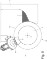
- Figure 4 illustrates a holding head 10 in the area of the holding station S1 in which the holding head 10 retrieves from the hopper 7 a double-length straw 1.
- Figure 5 illustrates a holding head 10 in the area of the cutting device 26 which divides in two the double-length straw 1 held by the holding head 10.
- Figure 6 illustrates a holding head 10 which holds two twin straws 1 produced by the central cutting of a double-length straw 1 and is between the cutting device 26 and the release station S2.
- Figure 7 illustrates a holding head 10 in the area of the release station S2 in which the holding head 10 releases to the corrugating drum 11 two twin straws 1 produced by the central cutting of a double-length straw 1.
- each holding head 10 comprises two twin transport assemblies 27 which are mounted so as to move along an adjustment direction A which is axially oriented (i.e. is parallel to the central rotation axis 9 of the retrieving conveyor 8) and is parallel to the straw 1 carried by the holding head 10 (i.e. is parallel to the longitudinal extension of the straw 1).
- Each transport assembly 27 of a same holding head 10 is configured to grab a respective portion of the double-length straw 1 (prior to the central cutting operated by the cutting device 26) and to grab a respective single-length straw 1 (after the central cutting operated by the cutting device 26).
- each transport assembly 27 of a same holding head 10 is provided with suction so as to hold with a certain strength the respective straw 1; i.e. each transport assembly 27 has a U-shaped sucking seat configured to couple to the straw 1.
- the suction through each transport assembly 27 of a same holding head 10 is activated in the holding station S1 and is deactivated in the release station S2.
- the retrieving conveyor 8 comprises an actuator device 28 configured to move the two transport assemblies 27 of a same holding head 10 along the adjustment direction A for alternatively arranging the two transport assemblies 27 in a holding position (illustrated in Figure 8 ) in which the two transport assemblies 27 are arranged at a mutual distance D1 and in a release position (illustrated in Figure 10 ) in which the two transport assemblies 27 are arranged at a mutual distance D2 greater than the mutual distance D1.
- the two transport assemblies 27 of a same holding head 10 are moved, by the actuator device 28 between the holding station S1 and the release station S2, along the adjustment direction A so as to be arranged from the holding position (illustrated in Figure 8 ) to the release position (illustrated in Figure 10 ) in which the two transport assemblies 27 are arranged at the mutual distance D2 greater than the mutual distance D1.
- the two transport assemblies 27 of a same holding head 10 engage respective central portions of the double-length straw 1 (i.e. engage ends facing the two single-length straws 1 obtained from the central cutting of the double-length straw 1), whereas in the release position (illustrated in Figure 10 ) the two transport assemblies 27 of a same holding head 10 engage respective end portions of the double-length straw 1 (i.e. engage opposite ends of the two single-length straws 1 obtained from the central cutting of the double-length straw 1).
- the retrieving conveyor 8 comprises a (U-shaped) countering element 29 which is arranged at the centre between the two transport assemblies 27 of a same holding head 10 and is configured to guide the cut performed by a blade of the cutting device 26.
- the countering element 29 moves integral with the retrieving conveyor 8 and thus does not translate together with the two transport assemblies 27.
- the retrieving conveyor 8 rotates around the rotation axis 9 so as to move the holding head 10 along the retrieving path P with a circular shape and the adjustment direction A is axially oriented, i.e. is parallel to the rotation axis 9.
- the retrieving conveyor 8 comprises, for each holding head 10, two guides 30 which are axially oriented (i.e. parallel to the adjustment direction A) and are arranged at the two opposite sides of the central countering element 29 and two slides 31, each of which is mounted so as to slide on a respective guide 30 and supports a transport assembly 27.
- the actuator device 28 comprises at least one fixed (i.e. it does not rotate together with the retrieving conveyor 8) cam arranged around the rotation axis 9 and, for each holding head 10, at least one cam follower which transmits an axial movement to the two slides 31.
- the two transport assemblies 27 of the holding head 10 are moved, by the actuator device 28, into the holding position (illustrated in Figure 8 ) so that when the holding head 10 arrives in the retrieving station S1 (as is illustrated in Figure 4 ) the two transport assemblies 27 of the holding head 10 are already in the holding position (illustrated in Figure 8 ).
- the two transport assemblies 27 of the holding head 10 grab a double-length straw 1 engaging respective central portions of the double-length straw 1.
- the holding head 10 moves from the retrieving station S1 up to arriving in the area of the cutting device 26 always keeping the two transport assemblies 27 in the holding position (illustrated in Figure 8 ); then, the central cutting of the double-length straw 1 takes place when the two transport assemblies 27 are in the holding position (illustrated in Figure 8 ) and the blade of the cutting device 26 cooperates with the countering element 29.
- the holding head 10 moves towards the release station S2 and, downstream of the cutting device 26, the actuator device 28 starts moving (moving away from each other) the two transport assemblies 27 along the adjustment direction A so as to progressively bring the two transport assemblies 27 in the release position (illustrated in Figure 10 ).
- the two transport assemblies 27 of a same holding head 10 are moved from the holding position to the release position only downstream of the cutting device 26.
- FIG 9 illustrates an intermediate position corresponding to the maximum mutual moving away of the two single straws 1. Namely, the movement of the two transport assemblies 27 of a same holding head 10 from the holding position (illustrated in Figure 8 ) to the release position (illustrated in Figure 10 ) also determines a movement of the two straws 1 along the adjustment direction A which spaces the two straws 1 apart from each other.
- two fixed containment panels 32 are provided which are on the outside of the retrieving conveyor 8 (i.e. are fixed and do not move together with the retrieving conveyor 8) and are arranged along the retrieving path P on opposite sides of the retrieving conveyor 8 in order to create a containment of the straw 1 along the adjustment direction A.
- the containment panels 32 prevent the two straws 1 carried by the two transport assemblies 27 of a same holding head 10 from exceedingly moving towards the outside in axial direction (i.e. along the adjustment direction A). Then, the two containment panels 32 create an external axial containment of the two straws 1 carried by the two transport assemblies 27 of a same holding head 10 defining limit stops for the movement of the two straws 1 along the adjustment direction A.
- a separation element 33 is provided which is on the outside of the retrieving conveyor 8 (i.e. is fixed and does not move together with the retrieving conveyor 8) and is arranged along the retrieving path P at least in the area of the release station S2 so as to be arranged at the centre between the two straws 1 carried by the two transport assemblies 27 of a same holding head 10 and, hence, keep the two straws 1 separate.
- the separation element 33 starts downstream of the cutting device 26 and ends in the area of the release station S2. Then, the separation element 33 creates an inner axial containment of the two straws 1 carried by the two transport assemblies 27 of a same holding head 10 preventing the two straws 1 from drawing close to each other.
- the separation element 33 has a size measured parallel to the adjustment direction A which progressively increases along the retrieving path P up to reaching a maximum in the area of the release station S2.
- the suction through each transport assembly 27 of a same holding head 10 is activated in the holding station S1 and is deactivated in the release station S2.
- the suction through each transport assembly 27 of a same holding head 10 is deactivated also when the two transport assemblies 27 move away from each other along the adjustment direction A for moving from the holding position (illustrated in Figure 8 ) to the release position (illustrated in Figure 10 ) so as to prevent the sliding of the transport assemblies 27 with respect to the straws 1 from generating excessive stresses on the straws 1.
- the suction through each transport assembly 27 of a same holding head 10 is deactivated when the two straws 1 end their mutual moving away, i.e. when the two straws 1 arrive in contact with the respective containment panels 32.
- each transport assembly 27 can be activated when the transport assemblies 27 are arranged in the holding position (illustrated in Figure 8 ) and is deactivated while the transport assemblies 27 are moved from the holding position (illustrated in Figure 8 ) to the release position (illustrated in Figure 10 ).
- the suction through each transport assembly 27 of a same holding head 10 can be reactivated after the two transport assemblies 27 of a same holding head 10 reach the release position (illustrated in Figure 10 ) and then again deactivated in the release station S2; alternatively, the suction through each transport assembly 27 of a same holding head 10 can remain deactivated until the holding head 10 returns in the holding station S1 (in any case the straws 1 remain on the inside of the respective transport assemblies 27 for the presence of containment elements which surround part of the retrieving conveyor 8 between the cutting device 26 and the release station S2).
- the retrieving conveyor 8 has, for each transport assembly 27, at least one suction opening 34 which is arranged in the area of the holding position (illustrated in Figure 8 ), can be connected to a suction source, and is configured to transmit the suction to the transport assembly 27 when the transport assembly 27 is in the holding position (illustrated in Figure 8 ).
- each transport assembly 27 moves away from the holding position (illustrated in Figure 8 ) for moving towards the release position (illustrated in Figure 10 ), it progressively moves away also from the respective suction opening 34 and then progressively deactivates the suction; the size of the suction opening 34 along the adjustment direction A is approximately equal to half of the overall away movement given to the two straws 1 so that the suction through each transport assembly 27 remains (more or less) active until the two straws 1 are moved away from each other and it interrupts when the away movement of the two straws 1 is completed. In this manner, the axial movement along the adjustment direction A of the two transport assemblies 27 of a same holding head 10 also produces the deactivation of the suction through the transport assemblies 27.
- each transport assembly 27 from the holding position (illustrated in Figure 8 ) to the release position (illustrated in Figure 10 ) could be comprised between 40 and 60 mm, whereas the two straws 1 could be moved away from each other by a distance comprised between 5 and 10 mm.
- each transport assembly 27 couples to a duct connected to the atmosphere for eliminating any traces of suction (depression) on the inside of the transport assembly 27 and thus eliminate every obstacle to the releasing of the straw 1 carried by the transport assembly 27.
- the packing machine 6 described above has numerous advantages.
- the packing machine 6 described above allows retrieving in a safe and reliable manner the straight straws 1 from the hopper 7 guaranteeing, simultaneously, with extreme precision the position of the ends when the straight straws 1 are released to the following corrugating drum 11.
- This result is obtained thanks to the fact that initially the two transport assemblies 27 of a same holding head 10 centrally grab a double-length straw 1 which is in the hopper 7 (and in this manner a possible arc-shaped curve of the double-length straw 1 does not cause any problem) and subsequently the two transport assemblies 27 of a same holding head 10 move towards the outside so as to guarantee (after the retrieval from the hopper 7) with high precision the position of the ends when the straight straws 1 are released to the following corrugating drum 11.
- the packing machine 6 described above requires minimum modifications with respect to an existing packing machine and therefore it is simple, cost-effective and compact to manufacture.
Landscapes
- Engineering & Computer Science (AREA)
- Mechanical Engineering (AREA)
- Wrapping Of Specific Fragile Articles (AREA)
- Specific Conveyance Elements (AREA)
Applications Claiming Priority (1)
| Application Number | Priority Date | Filing Date | Title |
|---|---|---|---|
| IT102023000003660A IT202300003660A1 (it) | 2023-03-01 | 2023-03-01 | Metodo e macchina di lavorazione di cannucce |
Publications (2)
| Publication Number | Publication Date |
|---|---|
| EP4455032A2 true EP4455032A2 (de) | 2024-10-30 |
| EP4455032A3 EP4455032A3 (de) | 2024-11-06 |
Family
ID=86329061
Family Applications (1)
| Application Number | Title | Priority Date | Filing Date |
|---|---|---|---|
| EP24160214.3A Pending EP4455032A3 (de) | 2023-03-01 | 2024-02-28 | Strohverarbeitungsverfahren und -maschine |
Country Status (2)
| Country | Link |
|---|---|
| EP (1) | EP4455032A3 (de) |
| IT (1) | IT202300003660A1 (de) |
Citations (1)
| Publication number | Priority date | Publication date | Assignee | Title |
|---|---|---|---|---|
| WO2021250715A1 (en) | 2020-06-10 | 2021-12-16 | I.M.A. Industria Macchine Automatiche S.P.A. | Machine and method for the automated production of straws |
Family Cites Families (1)
| Publication number | Priority date | Publication date | Assignee | Title |
|---|---|---|---|---|
| CN115429086A (zh) * | 2022-08-18 | 2022-12-06 | 浙江金申机械制造有限公司 | 吸管的制造方法 |
-
2023
- 2023-03-01 IT IT102023000003660A patent/IT202300003660A1/it unknown
-
2024
- 2024-02-28 EP EP24160214.3A patent/EP4455032A3/de active Pending
Patent Citations (1)
| Publication number | Priority date | Publication date | Assignee | Title |
|---|---|---|---|---|
| WO2021250715A1 (en) | 2020-06-10 | 2021-12-16 | I.M.A. Industria Macchine Automatiche S.P.A. | Machine and method for the automated production of straws |
Also Published As
| Publication number | Publication date |
|---|---|
| EP4455032A3 (de) | 2024-11-06 |
| IT202300003660A1 (it) | 2024-09-01 |
Similar Documents
| Publication | Publication Date | Title |
|---|---|---|
| JPH0427089B2 (de) | ||
| CN103702904B (zh) | 用于生产硬质包装的包装机和方法 | |
| EP4240573B1 (de) | Verfahren und vorrichtung zum biegen eines strohhalms | |
| AU688747B2 (en) | Method and apparatus for feeding, grouping and orientating articles | |
| JP6539725B2 (ja) | 包装機械 | |
| JP2022552205A (ja) | 注ぎ込み可能な製品を含有するシール済みの半完成パックを折り曲げユニットに送り込むための送り込みユニット | |
| JP6613228B2 (ja) | ロッド状の物品を運搬するためのシステムおよび方法、ならびにロッド状の物品をコンベヤーバンド内に保持するための配列および方法 | |
| US8464762B2 (en) | Straw packaging machine | |
| EP1494924B1 (de) | Einwickelmaschine | |
| EP0792807B1 (de) | Verfahren und Vorrichtung zum Falten von Verpackungszuschnitten entlang vorgefalzten Linien | |
| US7757466B2 (en) | Unit for packaging article containing infusion product | |
| CN101081646B (zh) | 香烟包装机械和方法 | |
| JP6487661B2 (ja) | 箱詰め装置 | |
| JPS60148429A (ja) | 物品を包装し集合化する機械 | |
| EP4458698A1 (de) | Verpackungsverfahren und verpackungsmaschine für strohhalme mit ausrichtung vor dem verpacken | |
| EP4313780B1 (de) | Maschine zum verpacken von produkten der tabakindustrie, insbesondere snus | |
| EP4458697A1 (de) | Verfahren und vorrichtung zum einwickeln von strohhalmen | |
| EP1714878B1 (de) | Maschine zum Umverpacken von Zigarettenpackungen | |
| CN116323441B (zh) | 用于包装产品或产品组的包装机以及操作这种包装机的方法 | |
| EP1808376A1 (de) | Vorrichtung und Verfahren zum Trennen der Öffnungselemente geliefert in Form einer Folie die einzeln auf den jeweiligen Verpackungen, samt fliessfähige Nahrungsmittel, angehaftet werden | |
| JP5964596B2 (ja) | 搬送設備、及び、カートナー又は、段ボールケーサー | |
| IT202300003660A1 (it) | Metodo e macchina di lavorazione di cannucce | |
| JP6018778B2 (ja) | 供給装置 | |
| EP1516835A2 (de) | Transportvorrichtung zum Befördern von quaderförmigen Artikeln | |
| JP2001097313A (ja) | 包装機 |
Legal Events
| Date | Code | Title | Description |
|---|---|---|---|
| PUAI | Public reference made under article 153(3) epc to a published international application that has entered the european phase |
Free format text: ORIGINAL CODE: 0009012 |
|
| STAA | Information on the status of an ep patent application or granted ep patent |
Free format text: STATUS: THE APPLICATION HAS BEEN PUBLISHED |
|
| PUAL | Search report despatched |
Free format text: ORIGINAL CODE: 0009013 |
|
| AK | Designated contracting states |
Kind code of ref document: A2 Designated state(s): AL AT BE BG CH CY CZ DE DK EE ES FI FR GB GR HR HU IE IS IT LI LT LU LV MC ME MK MT NL NO PL PT RO RS SE SI SK SM TR |
|
| AK | Designated contracting states |
Kind code of ref document: A3 Designated state(s): AL AT BE BG CH CY CZ DE DK EE ES FI FR GB GR HR HU IE IS IT LI LT LU LV MC ME MK MT NL NO PL PT RO RS SE SI SK SM TR |
|
| RIC1 | Information provided on ipc code assigned before grant |
Ipc: B31D 5/00 20170101ALI20241002BHEP Ipc: B65B 19/34 20060101AFI20241002BHEP |
|
| STAA | Information on the status of an ep patent application or granted ep patent |
Free format text: STATUS: REQUEST FOR EXAMINATION WAS MADE |
|
| 17P | Request for examination filed |
Effective date: 20250403 |