EP4454990A2 - Hydraulischer hochgeschwindigkeitswasserfahrzeugaufzug - Google Patents
Hydraulischer hochgeschwindigkeitswasserfahrzeugaufzug Download PDFInfo
- Publication number
- EP4454990A2 EP4454990A2 EP24172748.6A EP24172748A EP4454990A2 EP 4454990 A2 EP4454990 A2 EP 4454990A2 EP 24172748 A EP24172748 A EP 24172748A EP 4454990 A2 EP4454990 A2 EP 4454990A2
- Authority
- EP
- European Patent Office
- Prior art keywords
- lift
- cradle
- watercraft
- bunks
- beams
- Prior art date
- Legal status (The legal status is an assumption and is not a legal conclusion. Google has not performed a legal analysis and makes no representation as to the accuracy of the status listed.)
- Pending
Links
Images


Classifications
-
- B—PERFORMING OPERATIONS; TRANSPORTING
- B63—SHIPS OR OTHER WATERBORNE VESSELS; RELATED EQUIPMENT
- B63C—LAUNCHING, HAULING-OUT, OR DRY-DOCKING OF VESSELS; LIFE-SAVING IN WATER; EQUIPMENT FOR DWELLING OR WORKING UNDER WATER; MEANS FOR SALVAGING OR SEARCHING FOR UNDERWATER OBJECTS
- B63C3/00—Launching or hauling-out by landborne slipways; Slipways
- B63C3/12—Launching or hauling-out by landborne slipways; Slipways using cradles
-
- B—PERFORMING OPERATIONS; TRANSPORTING
- B63—SHIPS OR OTHER WATERBORNE VESSELS; RELATED EQUIPMENT
- B63C—LAUNCHING, HAULING-OUT, OR DRY-DOCKING OF VESSELS; LIFE-SAVING IN WATER; EQUIPMENT FOR DWELLING OR WORKING UNDER WATER; MEANS FOR SALVAGING OR SEARCHING FOR UNDERWATER OBJECTS
- B63C3/00—Launching or hauling-out by landborne slipways; Slipways
- B63C3/06—Launching or hauling-out by landborne slipways; Slipways by vertical movement of vessel, i.e. by crane
Definitions
- Conventional boat lifts often used for coastal settings are typically piling-mounted cable lifts, also known as pile lifts, which have two or more electric motors with gear boxes for pulling a cable to lift a cradle supporting a boat.
- the motors are mounted high enough (e.g., three to seven feet above dock level) to be clear of splashing water for avoiding water damage. Since the cradle is allowed to swing, the motors must be mounted high enough to have sufficient cable length to reduce cable fatigue, and there needs to be sufficient clearance between the boat and the pilings to avoid contact therebetween when the cradle sways.
- the above-mentioned conventional boat lifts have several problems. For example, they often have structure obscuring an operator's view and hindering boat boarding. The cradle and hence the boat also sway in the wind for the four post configuration.
- Electric motors with gear boxes are slow (e.g., typically approximately ninteen inches per minute), loud, limited by the practical amount of amps provided, and limited by the inefficiency of the gear box. Electric motors of conventional lifts are also vulnerable to submerging and corrosion. AC motors with a gearbox do not gain much speed when lowering. AC power (typically 220V, 30-40amp) mounted on conventional lifts and routed underwater creates a safety risk. High amp 220V power is sometimes difficult or not practical to get to the dock. Moreover, multiple motors get out of sync, requiring frequent releveling.
- a popular variation of a four post pile lift has a beam orientated fore/aft on each side of the boat and mounted on top of fore/aft pilings. Each side has a single motor which spins a pipe having a forward and aft cable wound on it. For larger lifts, additional cables may be wound on the pipe between the fore and aft cables. Often, a spindle with a helix shaped groove is attached to the pipe to keep the cable from overlapping, which causes wear and undesired noise.
- the fore/aft oriented lifting beams of conventional piling lifts obscure operator views and make boarding more difficult.
- a certain variation eliminates these two beams by using four motors positioned in each corner of the lift and mounted on each of the four pilings. This solves the problems associated with the top beams, but it adds cost and complexity by having four motors.
- the four motors/gearboxes are quite large, obscure operator views, and need frequent releveling.
- the electric motors are vulnerable to storm surge that often can destroy them by flooding above them.
- the electric motor on the outboard side requires high voltage/high amperage AC power to be routed underwater, which can be dangerous, adds complexity, and is a problem for dredging.
- the pilings are often positioned adjacent to the edge of the dock, there is a gap more than a piling's width between the boat and the dock for sway clearance. Centering the boat on the lift can cause a particularly wide gap between the boat and the dock which makes boarding more difficult and less safe.
- the motors are typically AC, since DC is lower voltage with higher amps, making it less practical to run power long distances to the far side of the lift due to the cost of the wire rated for high amps.
- the lifts often require high amp 220v power, which can be dangerous in a wet environment, since the motors are mounted on metal structure, and the power cables are routed underwater. Multiple motors also require adjustment over time to keep the cradle level, and increase failure risk.
- US Patent No. 8,777,513 does not require pilings above the dock, since its lift is hydraulic instead of electric.
- the cradle is supported by cables, which are pulled up by hydraulic cylinders positioned on each side of the boat and driven by a hydraulic pump that can be AC or DC powered.
- the challenge with this design is the practical limitation of the stroke of a hydraulic cylinder, especially considering the typical use is tidal regions that require long lifting range. This creates complexity of cable routing and limits the diameter of the pulleys.
- the limitation of lifting range, the high cost of this configuration, and difficult maintenance and installation has greatly limited the adoption in the marketplace.
- US Patent No. 6,230,639 is essentially a single motor version of the '360 patent. It was not produced since it did not overcome several technical challenges. The primary issue is the embodiment as shown cannot have practical lifting range, since the cable angle changes as it winds the helically grooved spools, which would eventually cause the cable to grind on the grooves or jump out of the grooves. This configuration also has the large spindle at three times the diameter of the smaller spindle. In practice, this would drive the larger spindle to be impractically large, since the smaller spindle has a minimum diameter that would not cause cable damage. This requires the spool to be approximately ten feet away from the pulley to get ten feet of range.
- US Patent No. 8,07,013 has no top beams and uses a single dockside electric motor. However, this configuration requires complex cable routing and still requires the motor to be mounted above the splash zone. This configuration is also not conducive for use of helix cable spindles to keep cables from bunching to provide adequate lifting range.
- US Patent No. 4,401,335 is directed to a boat hoist including a lift suspension system which results in even application of forces to points on a moveable platform remote from a point of attachment of the lifting device, thus eliminating twisting of the loaded platform.
- This system achieves equal loading of lift points by means of a cable arrangement similar to that of US5,427,471 (described below), which requires that one end of each of two cables be fixed below the surface of the water and suffers from that same disadvantage.
- US Patent No. 5,090,841 is directed to a boat lift in which a hydraulic pump and cylinder with a piston are mounted on a manual boat lift such that the piston rod carries a pulley.
- the pulley engages the lifting cable so that when the piston moves in the cylinder, the boat moves up or down.
- This system requires that part of the cable be immersed in the water while the boat is in the lifted position, which has the same disadvantages as US Patent No. 5,427,471 (described below).
- this system calls for a piston and cylinder in addition to lines and pulleys, which considerably adds to the maintenance costs of the system.
- US Patent No. 5,427,471 is directed to a boat lift including a vertical main post mounted on dock with the lower end mounted in the water but spaced above the floor of the water.
- a frame includes an outer guide post having a platform mounted on the water floor with an upper end above the water level. The frame is connected by a single member to the main post.
- a platform unit for supporting a small boat is slidably connected at both ends to the main post and the guide post, and a cable and winch unit is interconnected among the foregoing elements for effecting a level lifting and lowering of the platform unit into and out of the water.
- This system suffers from the defect that it requires one end of the cable to be secured at the bottom of the main post, at which point it is continually immersed in the water. This requires frequent replacement of the cable or the use of a non-corrosive cable material, which adds considerably to the cost of installation and maintenance. Also, because of the restricted size of the vessels that can be lifted by this device, use on large multi-hull vessels is impractical
- US Patent No. 5,769,568 discloses a conventional lift including two motors, two top rails, and four winders operating in a configuration as previously described. It has all the disadvantages of conventional lifts, namely more than one motor and two top rails.
- US Patent No. 5,772,360 discloses a conventional lift having two motors, no top rail, and two beams passing under the load.
- the dockside and water side of each beam is raised and lowered by separate cables, each being wound on spools driven by the motor on the dockside piling.
- These two lines have mechanical advantages of one and three, the different mechanical advantages being compensated for by differential drives on the motor.
- This arrangement has no top rails and two motors on the dockside but requires a differential gearing system.
- US Patent No. 5,957,623 describes a lift having no top rail and no motor. Instead, it includes a nut on a threaded vertical shaft. The nut is rotated to raise or lower a boat attached to the nut.
- US Patent No. 6,470,816 in a four post/dual motor embodiment, raises and lowers the vessel on two beams, one fore and one aft of the vessel, using two motors on the dock side and no top beam.
- This invention suffers from the fact that it is not stable to roll. Further, it requires that the cables be permanently secured below the water, which greatly shortens their life.
- US Patent No. 6,408,776 and US Patent No. 6,640,736 describe lifts having two beams under the vessel in the shape of a "V." Each lift is powered by a single motor at the top of the dockside post, the motor spooling two lines that are each reeved through pulleys to a waterside post with a mechanical advantage of three, and also spooling two other lines each connected to the dockside of one of the beams with a mechanical advantage of one.
- the two different mechanical advantages are offset by drums of different diameters.
- the two beams and the vessel are raised or lowered synchronously depending on the direction of rotation of the motor. These lifts have no top rail and only a single dockside motor.
- US Patent No. 6,484,655 describes a lift having one motor and no top rail. It has two beams in a "V" formation, similar to other three-piling lifts. It is subject to the limitation of the other three-piling lifts and in addition it is unstable to rolling.
- US Patent No. 7,070,171 is directed to a suspension and hoisting system including two cable circuits, each including a cable fixed at one end and attached to a lifting apparatus, such as a winch, at the other, and being reeved around deflection pulleys mounted on two parallel shafts located at either end of the load support.
- the lifting apparatus of each cable is mounted above the load support on the side of the load that is opposite its fixed end.
- the cable of at least one of the cable circuits is reeved successively around at least two coaxial deflection pulleys mounted on each end shaft in such a way that on at least one of the shafts at least one pulley of one cable circuit rotates in the same direction as at least one pulley of the other cable circuit under identical lifting and lowering action of the two lifting apparatus, while these two pulleys are constrained to rotate in opposite directions by any downwardly oriented force independent of the action of the lifting apparatus. Accordingly, these two pulleys are interlocked to reduce or eliminate any tendency of the load support to incline under the effect of this downward force.
- US Patent No. 7,117,805 describes another conventional lift including two motors, two top rails, and four winders operating in a configuration as previously described.
- This lift has the disadvantages of other conventional lifts, namely it requires two motors, one of which is on the waterside of the vessel. It also requires a top rail on either side of the vessel, both of which obstruct access to the vessel.
- US Patent No. 7,383,781 describes another conventional lift including two motors, two top rails, and four winders operating in a configuration as previously described. It has the disadvantages of requiring a top rail and having more than one motor.
- US Patent No. 7,407,150 provides a means of lifting boats and large loads via cables and pulleys alone and without submerged cables. It is stabilized against rotation by the arrangement of the pulleys and lines. It allows construction of a boat lift with only one motor but requires two top rails along the length of the vessel, which impede access to the vessel.
- US Patent No. 7,607,644 describes a lift having one top beam and no motors. It is limited to boats of 5,000 pounds or less because it is manually powered.
- US Patent No. 6,719,241 describes a lift that secures a cable to a spindle with the cable being clamped to the spindle and the cable going through a hole in the shank of a bolt.
- Embodiments of the present invention solve the above-mentioned problems and other problems and provide a distinct advance in the art of watercraft lifts. Specifically, the present invention provides a high-speed watercraft lift with improved operator visibility, watercraft boarding ergonomics, and reduced undesirable motion such as sway.
- An embodiment is a watercraft lift for raising and lowering a watercraft relative to a body of water, the lift comprising a cradle configured to support the watercraft, a cable suspending the cradle, a rotatable spindle configured take up the cable, and a submergible rotary motor.
- the cradle comprises a number of interconnected beams and a number of bunks connected to at least some of the interconnected beams.
- the cable is liftably linked to at least one of the interconnected beams.
- the rotatable spindle is configured to coil portions of the cable to raise the cradle and uncoil the portions of the cable to lower the cradle.
- the submergible rotary motor is configured to rotate the spindle.
- a watercraft lift comprising a cradle configured to support a watercraft, a number of cables suspending the cradle, a number of rotatable spindles configured to take up the cables, and a submergible motor.
- the cradle includes a number of interconnected beams and a number of bunks connected to at least some of the interconnected beams with the bunks being configured to support the watercraft.
- the cables are liftably linked to at least one of the interconnected beams.
- the rotatable spindles are configured to coil portions of the cables to raise the cradle and uncoil portions of the cables to lower the cradle.
- the submergible motor is configured to rotate the spindles so that the motor evenly lifts the cradle. At least one of the cables is liftably linked to at least one of the interconnected beams at a lift ratio of one to two. At least one of the cables is liftably linked to at least one of the interconnected beams at a lift ratio of one to
- a watercraft lift comprising a cradle configured to support a watercraft, a number of cables suspending the cradle, a number of rotatable spindles configured to take up the cables, and a motor.
- the cradle includes a number of interconnected beams and a number of bunks connected to at least some of the interconnected beams with the bunks being configured to support the watercraft.
- the cables are liftably linked to at last one of the interconnected beams.
- the rotatable spindles are configured to coil portions of the cables to raise the cradle and uncoil portions of the cables to lower the cradle.
- the motor is configured to rotate the spindles to that the motor evenly lifts the cradle.
- At least one of the cables is liftably linked to at least one of the interconnected beams at a lift ratio of one to two. At least one of the cables is liftably linked to at least one of the interconnected beams at a lift ratio of one to three. At least two of the rotatable spindles coil in opposite directions.
- a watercraft lift comprising a cradle configured to support a watercraft, a number of cables suspending the cradle, a number of rotatable spindles configured to take up the cables, and a motor.
- the cradle includes a number of interconnected beams and a number of bunks connected to at least some of the interconnected beams with the bunks being configured to support the watercraft.
- the cables are liftably linked to at last one of the interconnected beams.
- the rotatable spindles are configured to coil portions of the cables to raise the cradle and uncoil portions of the cables to lower the cradle.
- the motor is configured to rotate the spindles to that the motor evenly lifts the cradle.
- the motor and at least two of the rotatable spindles are coaxial relative to each other.
- the dual lift comprises first and second lifts each including a cradle, a number of cables suspending the cradle, a number of rotatable spindles configured to coil portions of the cables to raise the cradle and uncoil portions of the cables to lower the cradle, and a motor configured to rotate the spindles so that the motor evenly lifts the cradle.
- the first and second lifts share a piling beam such that the cables of each lift are at least partially suspended from the piling beam.
- a hydraulic watercraft lift comprising a cradle and a hydraulic power pack tower.
- the cradle includes a number of interconnected beams and a number of bunks connected to at least some of the interconnected beams with the bunks being configured to support the watercraft.
- the hydraulic power pack tower includes a tray bottom, a number of batteries positioned on the tray bottom, a hydraulic reservoir positioned above the batteries, and a hydraulic pumping unit (HPU) mounted on the hydraulic reservoir.
- HPU hydraulic pumping unit
- Another embodiment is a hydraulic watercraft lift comprising a number of piling beams, a cradle suspended from the piling beams, a control manifold, a control box, and a powerpack.
- the piling beams are positioned above a body of water.
- the cradle includes a number of interconnected beams and a number of bunks connected to at least some of the interconnected beams with the bunks being configured to support a watercraft.
- Each of the control manifold and control box are positioned near one of the piling beams.
- the powerpack is configured to power the hydraulic lift and at least one additional hydraulic lift.
- a watercraft lift comprising a cradle and a centralized air pump.
- the cradle includes a number of interconnected beams and a number of bunks connected to at least some of the interconnected beams with the bunks being configured to support a watercraft.
- the centralized air pump is configured to power the lift and at least one additional lift.
- a watercraft lift comprising a cradle, a cable suspending the cradle, a number of guides, and a number of mounting plates.
- the cradle includes a number of interconnected cross beams and a number of bunks connected to at least some of the interconnected beams with the bunks being configured to support a watercraft.
- the cable is liftably linked to at least one of the interconnected beams.
- the guides each have a flanged base. The mounting plates secure the flanged bases to one of the cross beams.
- a watercraft lift including a cradle, a cable suspending the cradle, and a freshwater hull rinse system.
- the cradle includes a number of interconnected beams and a number of bunks connected to at least some of the interconnected beams with the bunks being configured to support a watercraft.
- the cable is liftably linked to at least one of the interconnected beams.
- the freshwater hull rinse system is configured to rinse the watercraft.
- a watercraft lift comprising a cradle and a cable suspending the cradle.
- the cradle includes a number of interconnected beams and a number of bunks connected to at least some of the interconnected beams with the bunks being configured to support a watercraft.
- the cable is liftably linked to at least one of the interconnected beams.
- the interconnected beams include a crossbeam having a pulley insert positioned near an end of the crossbeam enabling shortening of the crossbeam.
- a watercraft lift comprising a cradle and a cable suspending the cradle.
- the cradle includes a number of interconnected beams and a number of bunks connected to at least some of the interconnected beams with the bunks being configured to support a watercraft.
- the cable is liftably linked to at least one of the interconnected beams.
- the lift is configured to be operated in conjunction with at least one other lift in a multi-pod lift configuration.
- Another embodiment is a watercraft lift comprising a cradle, a cable suspending the cradle, and at least two hydraulic rotary motors.
- the cradle includes a number of interconnected beams and a number of bunks connected to at least some of the interconnected beams with the bunks being configured to support a watercraft.
- the cable is liftably linked to at least one of the interconnected beams.
- One of the hydraulic rotary motors is positioned on a port side of the lift and one of the hydraulic rotary motors is positioned on a starboard side of the lift.
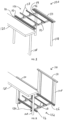
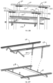
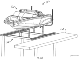
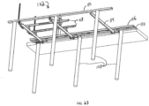
- a watercraft lift 100 constructed in accordance with an embodiment of the invention broadly comprises a cradle 102, a lift assembly 104, and a power system 106.
- the lift 100 may also include a plurality of pilings 108 connected together by piling members 110 from which the cradle 102 is suspended.
- the lift 100 may be used for raising and lowering watercraft, such as boat 112, in and out of a body of water.
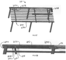
- the cradle 102 supports the watercraft and may include a number of interconnected beams, and specifically at least one forward and rear crossbeam 114, at least one catwalk 116, and boat bunks 118 configured to engage the watercraft.
- the crossbeams 114 may extend laterally between catwalks 116 and may be shaped as a rectangle with a T-shape on top to simplify clamping of the bunks 118, catwalks 116, and accessories.
- a second T-shape can be added to the bottom of the crossbeams 114 to facilitate mounting of an automatic boat cover or other accessories mounted to the bottom of the cradle 102.
- the open rectangle hides and protects an outboard cable (described below) inside the crossbeams 114.
- the rectangle may also enable the use of a cross beam pulley insert (described below).
- the catwalks 116 extend longitudinally between the crossbeams 114 and may be configured for being stepped on for boarding the watercraft or maintaining the lift 100.
- a catwalk 116 mounted atop and spanning the crossbeams 114 stabilizes the crossbeams 114 and improves access to the watercraft.
- another member, such as the bunks 118, may be needed to keep the crossbeams 114 from pivoting.
- the catwalk 116 also properly positions the crossbeams 114 fore/aft. To reduce tripping hazard, the catwalk 116 should be the same height as the piling member 110 when the cradle 102 is in a top position.
- the catwalks 116 may have a "whaletail" cross section, which maximizes a width of a walking surface (top of the catwalks 116) by cantilevering off the center box section.
- the walking surface may have shallow grooves for traction.
- the center box section may be minimized in volume to minimize trapped air and buoyancy.
- the center box section may have a small internal shelf or ledge (protrusion 238) to support a ballast 240 having cross section complementary to a portion of the cross section of the center box section, which enables the ballast 240 to be positioned above drain holes on the bottom of the center box section to maximize flooding.
- the ballast 240 may be approximately 50 pounds each to make it practical for one person to lift and install.
- the sides of the catwalks 116 flair outward toward the top to best support the cantilevered top.
- the catwalks 116 may have bottom lips that capture nuts to reduce the tools needed for installation.
- the cross section of the catwalks 116 may be fairly tall for improved bending stiffness. Two holes in the galvanized steel castings of each catwalk may accept a rope or cable for lifting and positioning the catwalks 116.
- the bunks 118 support the watercraft. Since the crossbeams 114 are stabilized by the catwalk 116 and not via the bunks 118 as with current piling lifts, the bunks 118 may be more flexible to better conform to the watercraft.
- the bunks 118 may also be adjustable in height using multiple holes 120, and adjustable laterally. Long bunk bracket inserts 122 provide approximately 2 feet of additional lifting height before an expected storm surge.
- the bunks 118 may be channel shaped for storing the inserts 122 in a hidden location under the channel shaped bunks 118.
- the outboard side of the cradle 102 must contact a portion of the piling member 110 both inboard and outboard of a pulley (described below) on the outboard piling member 110.
- Hammerhead-shaped pulley mounts may also be used to keep the outboard piling member 110 from twisting. Both hammerhead-shaped pulley mounts should contact the crossbeam 114 when the cradle 102 is pulled against the top position.
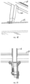
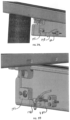
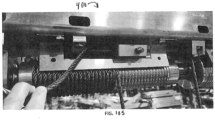
- the lift assembly 104 connects to the cradle 102 and may include cables 124 for lifting the cradle 102 and a torque tube 126 for taking up the cables 124.
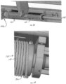
- the torque tube 126 may be oriented longitudinally (fore/aft, along the edge of a dock 128) and may have spindles 130 including helical grooves 132 thereon to guide the cables 124.
- the torque tube 126 may be supported via ball bearings 134, with one ball bearing on either side of opposing spindles.
- the spindles 130 may include a large spindle and a small spindle, the purpose of which will be described below.
- the torque tube 126 may be driven by a direct drive motor 136, preferably a hydraulic rotary motor with a brake, or other submergible motor such as a submergible electric motor.
- a piston-style rotational motor may be used for larger lifts due to its efficiency.
- the brake may be incorporated within the hydraulic motor to keep the cradle 102 and watercraft from lowering while the lift 100 is not being operated.
- a pressure compensator valve may be used to temporarily prevent lowering of the cradle 102, thus enabling the brake to engage and disengage. The brake may not engage unless the associated component(s) of the lift 100 is not moving, and disengaging the brake before hydraulic pressure is raised may cause the lift 100 to jolt down when the brake disengages.
- the motor 136 may be connected to the torque tube 126 by a chain coupler 142 that enables some misalignment.
- the torque tube 126 may be supported from above by the piling member 110, which spans between fore and aft pilings 108 adjacent to the dock 128.
- the cables 124 on the outboard side of the lift 100 are supported by another piling member 110 on top of outboard fore/aft pilings 108.
- the outboard cable 124 may be routed to provide a 3:1 lifting ratio, and the inboard cable 124 may be routed to provide a 2:1 lifting ratio.
- the spindle 130 for the inboard cable 124 may be 2/3 the diameter of the other spindle 130.
- a center of gravity of the combined watercraft and cradle 102 may need to be within the first 2/3 of the lateral distance of the cables 124 as measured from the dock side. Since it is desirable to have the watercraft favoring the dock side of the cradle 102 to minimize the gap between the watercraft and dock, it may be best to have the motor 136 on the dock side of the lift 100.
- the spindles 130 may be co-axial to the motor 136, which creates a vertically compact mechanism. Adding ballast on the dock side increases this stability and assists keeping tension on the cable 124 when submerging the cradle 102, otherwise the cable 124 may snarl on the spindle 130 if unloaded when lowering.
- This configuration is practical since watercraft are typically positioned to the dock side of a centerline of the cradle 102 to minimize a gap between the watercraft and the dock 128 for easier boarding.
- port and starboard submergible motors with the same lifting ratio may be used, but a single motor has less cost and does not require releveling.
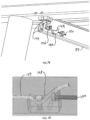
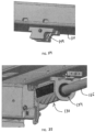
- the outboard cable 124 may be secured to the end of a helical groove 132 on the large spindle 130 to a laterally oriented pulley 144 on the inboard side of a first one of the crossbeams 114, across to a laterally oriented pulley 144 on the outboard side of the first crossbeam 114, up to a pulley 144 on the outboard piling member 110, down to a turning block 146 on the outboard side of the first crossbeam 114 and secured by a clamp 148 that can be fine tune adjusted by pulling the clamp 148 with a bolt 150.
- the inboard cable 124 is secured to the end of a helical groove 132 on the small spindle 130, to a longitudinally oriented pulley 144 on the inboard side of the first crossbeam 114, up to a turning block 146 on the inboard piling member 110, and secured by a clamp 148 that can be fine tuned by pulling the clamp 148 with a bolt 150.
- the forward set of cables 124 have a similar routing but opposite/mirrored relative to the aforementioned routing, which balances uneven longitudinal loads to keep the cradle 102 from shimmying when operating.
- the longitudinal loads may be caused by uneven cable angles and cable speeds. If routing of the forward set of cables 124 was not mirrored, the loads would be additive instead of canceling. Winding of the spindles 130 may be opposite/mirrored as well to facilitate canceling the longitudinal loads.
- the cables 124 may also be configured to pull the cradle 102 against the piling members 110 to keep the cradle 102 from swinging in the top position.
- the two pulleys 144 on the inboard side of the crossbeam 114 may be mounted on a removable insert 152 that attaches to the inside of the crossbeam 114 via a single bolt 154.
- the crossbeam 114 may be cut on its dockside end and a hole for attaching the insert 152 may be drilled in the shortened crossbeam 114.
- a lengthening insert can be used.
- the lift 100 may also include vertically extending guides 230 for assisting the placement of watercraft over the bunks 118.
- Each guide 230 may include a flanged base 232 configured to be mounted on one of the crossbeams 114 via a mounting plate 234 and corresponding brackets 236.
- the crossbeams 114 may be T-shaped for securing the guides 230 thereto.
- Additional crossbeams 244, often used for platforms, can be added by attaching an additional torque tube 246 to the torque tube 126 opposite the motor 156.
- the additional torque tube 246 may have a set of spindles 248 and cables 250 leading to the additional cross beams 244. Extensions 252 of the inboard and outboard piling members 110 may also be used.
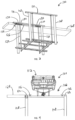
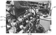
- the power system 106 rotates the torque tube 126 to raise and lower the cradle 102 and broadly comprises a motor 156, a powerpack 158 and a control system 160 including a controller 162.
- the motor 156 may be a rotational hydraulic motor or other motor that is preferably submergible to enable a lower profile.
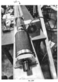
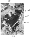
- the powerpack 158 includes a hydraulic power unit (HPU) 164 including one or more electric motors 166 driving one or more hydraulic pumps 168 and a reservoir 170 of hydraulic fluid. To greatly reduce corrosion and noise, the motor 166 may be mounted under the hydraulic fluid, inside the reservoir 170. This also greatly decreases the sound level when the motor 166 is running.
- HPU hydraulic power unit
- the power system 106 may further comprise a control manifold 172 including proportional directional valves 171, a pressure transducer 173, switching valves 174, a dump valve 175, a pressure compensating load holding valve 176, a brake release valve 178, a pressure reducing valve 180 for the brake, and a flow control valve 184.
- a control manifold 172 including proportional directional valves 171, a pressure transducer 173, switching valves 174, a dump valve 175, a pressure compensating load holding valve 176, a brake release valve 178, a pressure reducing valve 180 for the brake, and a flow control valve 184.
- These components may be integrated with the HPU 164 or separate therefrom (e.g., located near the pilings 108, piling members 110, and/or cradle 102).
- a DC configuration of the power system 106 may also include batteries 186 and solenoids 188 to start the electric motors 166.
- Hoses 190 may connect the hydraulic motor 156 and the brake with the manifold 172.
- the brake may be hydraulically activated (e.g., released when the brake is pressurized) and may be integrated in the hydraulic motor 156 or separate.
- the pressure compensating load holding valve 176 in the HPU 164 also prevents lowering by blocking fluid flow, but this can leak over long periods of time. Having the pressure compensating load holding valve 176 stop the lift 100 enables the brake to fully engage since the brake may not engage unless the corresponding components of the lift 100 are not moving.
- the power system 106 measures hydraulic pressure and rotations of the hydraulic motor 156 via an encoder. Amps of the electric motor 166 (for an AC version) can also be measured to operate the lift 100 at maximum speed using the maximum available amps. If the powerpack 158 is AC-based, the powerpack 158 may use a variable frequency device (VFD) 194, which dictates a speed of the electric motor 166 by varying frequency thereto. The powerpack 158 may alternatively be DC-based, which may be ideal for locations without adequate AC power.
- VFD variable frequency device
- the controller 162 may be controlled via a remote control transmitter 196, a smartphone app 198, and a manual up/down switch 200.
- the controller 162 may be or may include a microprocessor, which controls the logic for the power system 106, and a memory for storing data, commands, settings, measurements, computer code, and the like. Settings in the controller 162 can be set using the smartphone app or directly with buttons on the controller 162.
- the controller 162 may implement aspects of the present invention with one or more computer programs stored in or on computer-readable medium residing on or accessible by the controller 162. Each computer program preferably comprises an ordered listing of executable instructions for implementing logical functions in the controller 162.
- Each computer program can be embodied in any non-transitory computer-readable medium for use by or in connection with an instruction execution system, apparatus, or device, such as a computer-based system, processor-containing system, or other system that can fetch the instructions from the instruction execution system, apparatus, or device, and execute the instructions.
- a "computer-readable medium" can be any non-transitory means that can store the program for use by or in connection with the instruction execution system, apparatus, or device.
- the computer-readable medium can be, for example, but not limited to, an electronic, magnetic, optical, electro-magnetic, infrared, or semi-conductor system, apparatus, or device.
- examples of the computer-readable medium would include the following: an electrical connection having one or more wires, a portable computer diskette, a random access memory (RAM), a read-only memory (ROM), an erasable, programmable, read-only memory (EPROM or Flash memory), an optical fiber, and a portable compact disk read-only memory (CDROM).
- RAM random access memory
- ROM read-only memory
- EPROM or Flash memory erasable, programmable, read-only memory
- CDROM portable compact disk read-only memory
- the HPU 164 can be a vertical tower, which resembles a dock powerpost and has a minimal footprint. An airbell lid over the HPU 164 makes the HPU 164 submergible.
- the HPU 164 may further comprise a washdown system 206 including a water manifold 208 that accepts pressured fresh water, is operated via the controller 162, and has multiple valves to direct water to hoses 212 leading to spray nozzles 214 configured to spray the water at the watercraft thereby washing or rinsing the watercraft.
- the washdown system 206 may be configured such that it automatically operates upon a predetermined condition such as when the cradle 102 is at a predermined position (e.g., the top position), or when the watecraft is being lifted.
- the powerpack 158 may be a shared powerpack system, whereby the HPU is a central HPU configured to power multiple hydraulic devices (such as lifts and/or hydraulic automatic boat covers). Each hydraulic device may have a remote control (and transmitter), a microprocessor and memory, and a hydraulic manifold with up/down valves. The controller and manifold may be located near each lift, but the HPU may be located at a distance therefrom, even off the dock, which saves space and reduces noise. DC power from the HPU may power the electronics and valves of the manifold of each hydraulic device.
- a bundle of wires connected to all devices leading to the powerpack 158 may individually start up individual electric motors in the HPU 164, controlled from the microprocessor on each device, to assist in the smooth acceleration and deceleration. Control logic of the microprocessor can prevent more than one lift from operating at a time by sensing if the signal wire for one motor is powered or not.
- the shared powerpack system may also use networking, such as CanBus, to have multiple controllers collaborate with each other.
- each of the multiple motors may be started and stopped sequentially using the local microprocessor on a device.
- This microprocessor may provide other convenient features, such as automatically moving the corresponding lift to a predetermined position using a double tap command on the transmitter. Stops may include a top position, a bottom position that delineates a downward-most position, a mid or intermediate position for boarding, an engine start position that has the watercraft's lower unit in the water and while the watercraft is supported on the bunks, and a float position that enables the watercraft to travel on and off the lift.
- the engine start and floating position may be dictated by a set distance from a position which has a decrease in hydraulic pressure.
- a water level sensor such as Lidar or sonic sensor
- a running average pressure may be used to smooth out pressure spikes to give the microprocessor even data.
- the shared powerpack system may stop if the pressure suddenly increases faster than expected, such as colliding with an object.
- the power system 106 may enter a creep mode and thereby operate at a low speed, which may be used for replacing cables.
- the creep mode may be exited automatically when the lift 100 is pressured against an upper stop, which automatically sets the up position, and zeroing out the teeth count of the encoder.
- the lift 100 may then decelerate when approaching the top position for a soft landing, and stop when hydraulic pressure increases by approximately 300psi. This also reduced the amount of hydraulic pressure when resting.
- the up position may be set on each cycle. This may prevent over tensioning and breaking of a single cable in case the cradle 102 is not properly leveled.
- Each powerpack 158 may have one or more motors sharing a reservoir. In one embodiment, up to two powerpacks (four motors) may be used in a shared powerpack system.
- the powerpack 158 may have a pressure hose 216 and a return line 218 such that fluid flows only in one direction. If multiple powerpacks are used, their reservoirs may be connected to enable equalization of flow.
- a breather cap on a second powerpack may have a higher psi, such as 6 psi versus 3 psi on a breather cap of the first powerpack's reservoir.
- a floating ball check valve could also be used in the breather caps for a similar purpose.
- a dump valve may depressurize the HPU 164 by releasing the high pressure side to the reservoir, which provides smoother operation and improved reliability.
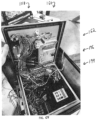
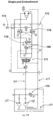
- the powerpack 158 may have a tower-like shape, with a battery tray 220 near its bottom, a stack of batteries 186 on or above the battery tray 220, and the HPU 164 and reservoir 170 above the batteries 186.
- a brass buss bar may connect the batteries 186 for clean design and high efficiency.
- An inline fuse may connect pairs of 12V batteries to protect against a short. Securing straps from the battery tray 220 and the reservoir 170 may sandwich the batteries 186 to secure them.
- a thin rubber layer 224 over the batteries 186 may help secure the batteries 186 from shifting.
- a waterproof bell 226 makes the whole powerpack 158 submergible.
- the batteries 186 may be charged via an AC trickle charger with only 6 amps of 110V max or via solar panels. This is a large improvement from conventional electric lifts, which typically need an expensive 30-50A 220V circuit and require an electrician.
- pneumatics may be used instead of hydraulics. That is, a powerpack may power multiple watercraft lifts via a shared air pump.
- the controller 162 By measuring hydraulic pressure, number of turns of the hydraulic motor 156 and AC amps, the controller 162 has a number of useful features, which will now be described.
- Acceleration/deceleration when the lift 100 starts moving, motion accelerates to full speed over a set time, such as 1-2 seconds. When a user gives a stop command, the lift 100 may decelerate over a set period of time, such as 1 sec. This prevents abrupt start/stopping and provides smooth operation.
- Speed can be controlled using adjustable flow control valves, a flow controller, staging timing of turning on individual HPU electric motors, or via a VFD in the case of an AC system.
- Soft stop at top when lifting, the lift may decelerate when approaching the top position.
- the controller 162 sets the top position on every cycle by zeroing out the teethcount, so it automatically self-calibrates.
- the lift 100 may stop, which prevents extra resting hydraulic pressure and unnecessary cable pull. It also creates a soft stopping motion.
- an up command may be disabled to prevent the user from building unnecessary hydraulic pressure.
- the controller 162 may allow an up command again.
- the lift 100 may slow when approaching the bottom position, which is preset in the app or the controller 162.
- the cradle 102 may stop if the cradle's motion is mechanically restricted in going up or down. If the cradle's motion is restricted in going down, the cables 124 could unload and snarl on the spindles 130. To prevent this, when the lift 100 is going down, the controller 162 may determine if the cradle 102 is loaded (i.e. with the watercraft on it), or unloaded. If unloaded, the cradle 102 may stop if hydraulic pressure drops under a set threshold set in the app or on the controller 162. After stopping, the down command may be disabled until an up command is given. A warning message may be displayed in the app.
- the lift 100 may enter slow motion mode if hydraulic pressure drops a predetermined amount within a defined timeframe, such as 1 ⁇ 4 second. If hydraulic pressure continues to drop after another timeframe, such as 1 ⁇ 2 second, the lift 100 may stop and down commands are disabled until an up command is given. A warning message may be displayed in the app.
- the thresholds need to be set to differentiate a pressure drop from a collision from a pressure drop due to launching the watercraft.
- Lowering cradle slows when submerging: the cables 124 can unload and unspool if the cradle 102 is lowered into the water too fast. To prevent this, the lowering of an empty cradle 102 automatically slows when pressure drops a determined threshold, such as 100 psi. The speed stays in slow motion mode until the lift 100 goes up a predetermined timeframe, such as 5 seconds. This makes it easier for the user to fine tune the elevation of the bunks 118 while watercraft is partially or fully floating. Another means of slowing the unloaded descending cradle 102 is to have the control logic operate only one motor 166 when going down when unloaded after crossing the mid position.
- the power system 106 may measure the water level using lidar, sonic, or other measuring means, and have the controller 162 slow the decent when the tooth count approaches the water level.
- the controller 162 may be controlled by only one motor 166 under the set mid position if there is no watercraft on the lift 100 as determined by a hydraulic pressure, such as less than 1500psi.
- Slow motion when launching when the controller 162 determines the cradle 102 is loaded (via a hydraulic pressure over a set threshold value while lowering), the lift 100 may slow when hydraulic pressure starts decreasing, which gives the user more fine tune control. Slow motion may be deactivated when lift goes up for a set time, such as 5 seconds.
- Slow motion when loading when the cradle 102 starts lifting a floating watercraft, the lift 100 goes into slow motion when the hydraulic pressure increases a set value over a set period of time, such as 1 second.
- the lift 100 may return to normal speed after 5 seconds of going up.
- the cradle 102 may raise to full speed until it decelerates when approaching the top position (as defined by last cycle). The cradle 102 may stop when hydraulic pressure raises over a defined threshold. If the controller 162 determines the watercraft is on the cradle 102, e.g., via a hydraulic pressure over 1500psi, the cradle 102 may stop at the set mid position.
- Floating position routine when a float command is given, the lift 100 may start lowering and the controller 162 may determine if the cradle 102 is loaded or not loaded by measuring pressure. If the cradle 102 is unloaded, the cradle 102 lowers until the hydraulic pressure decreases beyond a predetermined threshold as the cradle 102 contacts the water surface and the lift 100 goes into slow motion mode. The cradle 102 may continue to lower a user set amount such as the level to which the watercraft can float on or off the lift 100. If the cradle 102 is loaded, the cradle 102 may lower until the hydraulic pressure raises to a predetermined threshold, which actives slow motion mode.
- the cradle 102 may continue to lower a set number of revolutions and decelerate to a stop at an elevation below the surface of the water set by the user, that enables the engines to start while their lower units are in the water, but the watercraft is firmly secured on the bunks 118. Pressing the float command again may lower the cradle 102 to the full floating position.
- the water level can also be determined via sensors.
- Max amps for the AC version, a setting can limit the maximum amps used, so the user can set the lift 100 for maximum speed without popping a breaker, depending on power available at the dock 128. Amps are either measured or calculated by measuring hydraulic pressure.
- Variable speed hydraulics for the AC version, the lift's normal operating speed may be determined by setting the motor speed that uses the maximum set amps. For AC power, the motor speed may be changed using the VFD 194 by varying the frequency of the electric motor 166. For DC power, the motor speed may be changed with variable flow valves.
- Over-capacity stop if the hydraulic pressure goes above a set threshold, the lift 100 may stop, and the up command is disabled until a down command is entered.
- An over-capacity warning may be displayed in the app, a sound notification may be emitted, and/or a light may be illuminated on the controller 162.
- Override when override is selected in settings, all the above logic may be suspended, enabling only up and down functions.
- Boat weight the app may display the approximate watercraft weight using predetermined calibration of hydraulic pressure versus weight.
- Calibrate to determine the hydraulic pressures of the cradle when it is not loaded, activating calibrate when the cradle 102 is unloaded may lower the cradle 102 for a short time (e.g., 2 seconds), raise the cradle for a short time (e.g., 2 seconds) in slow motion, and store the measured hydraulic pressure of both in memory.
- a short time e.g. 2 seconds
- a short time e.g. 2 seconds
- a platform 256 may be added to the crossbeams 114 and/or piling members 110 for improved access to the watercraft's hull, and for appearance. Extension wings 258 of the platform 256 may be added to either side for ease of maintenance of the watercraft's outboard motor(s).
- an additional crossbeam 244 may be added with additional spindles 248.
- a torque tube extension 246 from the lift drives these spindles 248 at the same rate, and additional cables 250 are adjusted like the cables 124.
- a tube 254 may be mounted on one of the pilings to enable the torque tube extension 246 to pass therethrough.
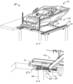
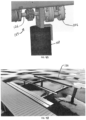
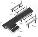
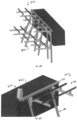
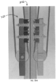
- FIGS. 84-101 another embodiment is a lift 300 in an elevator configuration including tracks 302 on a dockside of the lift 300.
- the lift 300 further includes powerpacks, a control system, and rotational hydraulic motors similar to the corresponding components of the piling configurations described above.
- the primary difference is that the cradle 310 rides up and down on two or more tracks 302.
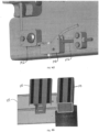
- a dockside piling member 312 secures a spinning torque tube 314 with four spindles 316.
- Each cable 320 is secured to the end of a helical groove in a spindle 316, wraps around the spindle 316 to a longitudinal pulley 322 on a carriage 324 to a turning block 326 on the piling member 312, and is secured to a cable clamp 328 that is adjusted with a bolt 330, as in the piling configuration.
- Another cable 320 is routed as a mirror image to the first to another pulley 322 on the cradle 310. Additional cables 320 are routed the same way on a second cradle 310. The mirror routing causes balanced side loading on the cradles 310.
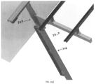
- a rear cross beam 332 is connected to either the top of the first cradle 310, with a support gusset 334 underneath, or for shallow water applications, the cross beam 332 may attach to the lower part of the cradle 310 with a gusset 338 mounted on top of the cross beam 332.
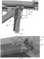
- the track 302 may be installed at multiple angles, such as 0, 11 or 22 degrees based on a desired load on the dock 336, water depth and function.
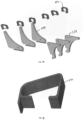
- the same lift 300 can be configured in these 6 different configurations via a kit that include cross beam gussets 334 or 338 and track angle brackets (TAB) 340 that attach the track 302 to the piling member 312. Upper wheels 342 of the carriage 324 contact the TAB 340 in the up position.
- TAB track angle brackets
- the gussets 334 or 338 are preferred over a diagonal tube since the loads are high and are distributed amongst several bolts versus a single pin joint.
- the gusset 338 has a convex shape on the diagonal to give more clearance for pontoon boats when gusset 338 is on top of the cross beam 332 and enables use in a hole when used under the cross beam 332.
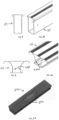
- the TAB 340 may include an open shape, with an opening wider than the spindle 316 to enable to install it after the spindle 316 is installed.
- a hole in the inboard side of the TAB 340 may be used as a drill template to drill a mounting hole after an I-beam 332 is cut down to size to form the track 302. Only one bolt is required since the TAB 340 is naturally loaded downward, and the bottom of the TAB 340 contacts the top of the I-beam 332.
- the inboard side of the TAB 340 may be 0.7 inches outboard of the inboard side of the track 302, to give clearance for the I-beam 332 to be mounted to the dock 336. Two holes on top of the TAB 340 are used to secure the TAB 340 to the bottom of the piling member 312.
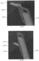
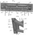
- Each carriage 324 has a set of four upper wheels 342 and two lower wheels 344.
- the track 302 may be an I-beam 332 shape with large internal radii and a soft external convex radius on an outboard facing side.
- the upper wheels 342 may have a radius on an inside edge of the wheel 342 that is smaller than the internal radii of the I-beam 332, such that if the carriage 324 shifts fore or aft, the edge of the wheel 342 will start to climb this internal radius, providing a fore/aft force to center the carriage 324, which prevents the carriage 324 from rubbing on the I-beam 332.
- the lower wheels 344 have a mating concave shape that naturally center on the outboard convex shape of the I-beam 332.
- the lower wheels 344 are supported by carriage side plates 348.
- Conventional elevator configuration lifts use a pivoting car assembly to enable multiple wheels to obtain even loading.
- the present invention eliminates the pivoting car by providing flexibility, tighter tolerance, and higher wheel loads.
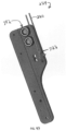
- the upper wheels 342 may have flexibility with single sheer axle 350, and the thickness of the side plate 348 where the axle 350 engages is thinned using a boss 352 on the outside.
- the carriage 324 and cross beams 332 may all be numeric-control machined without welding to achieve tight tolerances. Higher loads may be accommodated by reducing a vertical distance from the top to bottom sets of wheels.
- the wheels may be constructed of solid aluminum, vs the traditional plastic or rubber.
- the higher loads improve load distribution between the wheels due to higher deflection.
- the shorter height of the carriage 324 may also be beneficial for use in shallow water and enables a watercraft to be closer to the dock 336 when the gusset 338 is on top of the crossbeam 332.
- the carriage side plate 348 may be narrowed in width near the lower wheels 344 to provide for additional flexibility to enable more even loading of the lower wheels 344. This narrow shape, combined with the narrow bottom side of the gusset enables the bottom ten inches of the crossbeam/carriage to be used in shallower water when a hole is dug around this detail on the seabed.
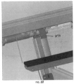
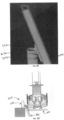
- a track mount 354 clamps to the track 302 and can be mounted to a piling, bulkhead or dock, enabling the piling member 312 to be mounted at or above dock height.
- the track mount 354 may be elongated to accommodate each form of mounting.
- Two angle beams 356 may be bolted to a center channel bracket 358 so each angle beam 332 clamps on the inboard flange of the I-beam 332, and the bolt is close to the inside edge of the I-beam 332.
- the channel backet 358 may be bolted on a high position if the top of the I-beam 332 is below the level of the dock 336, with two clamping bolts below, or a second position that is further down, and between upper and lower clamping bolts.
- the angle beams may be fairly narrow, such that the I-beam 332 can be positioned approximately 1.5 inches from the top edge of the dock 336. This gap is convenient since a locating jig used to position the I-beams 332 has a 1.5 inch thickness if constructed from 2 x 4 wood.
- a cable retention bracket 360 may be used to retain the cable 320 on the spindle 316 if the cable 320 is unloaded. In the elevator configuration, this bracket 360 may be mounted on the dock side to give clearance for the cable adjusters.
- a lifting range may be increased when a storm surge is approaching by either adding extension inserts between the bunks and the bunk brackets, or by utilizing a pivoting L-Shaped bracket with a short and long side.
- a multi-pod set 400 includes multiple lifts 402, 404 (each being a pod) synchronized for level lifting.
- a multi-pod set may comprise two or more of the above piling lifts oriented fore and aft.
- a controller measuring teethcount of both pods, using the encoders, may slow a faster pod to match a position of the slower pod.
- the controllers may be networked together via CanBus or the like to communicate both teethcount and hydraulic pressure. If each pod is capable of lifting 12,000lbs, for example, a two pod set lifts 24,000lbs, a three pod set lifts 36,000lbs and so on, using many common parts. Motors may also be synchronized by mechanically connecting them. Corresponding cables should be adjusted properly to avoid being overloaded.
- the pods may make adjustments in position to accommodate hull shape. While lifting, if one of the pods is determined to be overloaded, that pod may be disabled, and the other pods may be allowed to travel a set maximum distance, such as six inches. If the overloaded motor continues to experience hydraulic pressures over a threshold, the overloaded motor may quickly stop, and if the other motors reach a set maximum distance, the multi-pod set may stop, and the only operation allowed is a down operation.
- PV flow controllable directional proportional valve
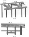
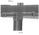
- a dual lift set 500 may include two piling lifts 502, 504 sharing a common center lifting beam 506, which may save width and cost.
- This configuration may be installed in a U-shaped slip with docks on either side.
- the hydraulic motor and spindles sets for each lift may be adjacent to each dock.
- the center lifting beam 506 has pulley sets for each lift.
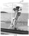
- a lift 600 ideal for a small watercraft comprises two tracks 602 supported at their top ends by a facia plate 604 mounted to a dock.
- the lower part of the tracks 602 may be secured either in the seabed, with a lower lateral beam 606 spanning to adjacent pilings 608, or with diagonals 610 to the dock.
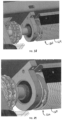
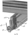
- the lift 600 may also comprise a top beam assembly 612 including a top beam 614, a rotary hydraulic motor 616, a motor mount 618, mirrored cable spindles 620, a brake 622, and a brake mount 624. No bearings are needed since the motor 616 and brake 622 serve this purpose.
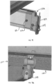
- the lift 600 may also comprise a carriage 626 for each track 602, the carriage 626 including side carriage plates 628 with upper wheels 630 and lower wheels 632 to take the vertical load, and side wheels 634 on the upper and lower sides of each carriage plate 628 to keep the carriage 626 from binding.
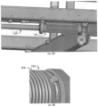
- a lifting beam 636 connecting left and right carriages 626 may include two cable pulleys 638. Two cables 640 may be secured on each of the spindles 620 and routed around a pulley 638 on the carriage lifting beam 636 to a turning block 642 under the motor mount 618 or brake mount 624 to an adjustable cable clamp 644.
- An arm 648 of the cradle 646 may be secured to each carriage 626 and a diagonal support 650 for the arm 648 may be on the bottom or the top of the arm 648 and connected to each carriage 626.
- the diagonal support 650 may be on top of the arm 648 for shallow water applications.
- Bunks 652 of the cradle 646 may be attached to the arms 648 for supporting the watercraft.
- the arm 648 can be long enough for the bunks 652 to accept two small watercraft such as two personal watercraft (PWC) either parallel to the dock or perpendicular to the dock.
- PWC personal watercraft
- a walkway 654 may also be included to go around the watercraft for ease of access.
- each spindle 620 may have spring loaded cable keepers 656. Pre-coiled cables may also be used to be retained on the unloaded spindle 620 without cable keepers.
- a lift 700 utilizing this configuration does not have computer control, encoders, or pressure sensing, which lowers cost and features.
- the lower position is set using a limit switch.
- Conventional electric lifts use a rotary limit switch which would would work for this application but are not reliable because they have internal moving pieces.
- the lift 700 provides a more reliable means-an electrical probe 702 positioned to touch the cable when the cradle is in a desired lowered position.
- the cradle and hence the cable is grounded, and when the probe 702 contacts the cable, a normally open solenoid turns off the power to the down solenoid, stopping the downward movement of the lift, but enabling up movement.
- a similar probe may be mounted on each of the spots where the crossbeams contact the upper beam and stops the lift when contact is made with the probe.
- the present invention is a high-speed (multiple times as fast as conventional lifts) watercraft lift that has the lifting mechanism hidden from view, exhibits no sway in the up position, and provides unobstructed boarding with minimum gap between the watercraft and the lift. Configurations include being supported on four or more pilings, or a cradle being guided using two or more tracks.
- the present invention provides the first watercraft lift with a hydraulic rotational motor and the first watercraft lift including computer control enabling advanced functionality.
- the present invention includes reliable sensors for hydraulic pressure and hydraulic motor rotations.
- the present invention includes an advanced control system that accelerates and decelerates upon starts and stops, slows the lift when approaching the top position, has collision detection and avoidance, and can position the lift to pre-determined levels under a changing water level for full floating and engine start positions.
- the approximate weight of the watercraft may be displayed in a smartphone app by measuring hydraulic pressure, and the lift may be prevented from being overloaded by limiting hydraulic pressure.
- the DC powered embodiment may control speed by independently controlling multiple electric motors driving hydraulic pumps and/or with a hydraulic proportional valve.
- the HPU may be compact with the electric motor under the hydraulic fluid to prevent corrosion and reduce sound.
- the AC powered embodiment may include a VFD that controls motor speed.
- the maximum AC amps used may be set to use the available maximum power, and the lift may operate at the maximum amperage which maximizes speed, especially for lowering and operating with an empty cradle.
- the cradle In the up position, the cradle may be secured against the top piling member, which prevents the cradle from swaying.
- the lift may be controlled with buttons on a control box near the lift, via a transmitter, or via a smartphone app.
- the lift stays level via a single motor, or the lift may stay level via a microprocessor utilizing data from digital encoders from separate motors. Levelness may be fine tuned via cable adjusters with course and fine tuning adjustability.
- the bunks and catwalks may be secured with clamps to a T topped rectangular beam.
- a single HPU may power multiple lifts, with each lift having a control box, control manifold, remote control and microprocessor.
- Additional challenges created yet overcome by the present invention include abrupt starting and stopping, bearings supporting torque tubes wearing out and undergoing high friction, high cost and complexity of hydraulics, and functionality of using a brake for a hydraulic motor under high loads.
- Yet further challenges created yet overcome by the present invention include fore and aft cradle sway when operating with high acceleration due to cable angles, and cogging of hydraulic motors causing vibration at slow speeds unless the hydraulic circuit provides even hydraulic pressure.
- references to “one embodiment”, “an embodiment”, or “embodiments” mean that the feature or features being referred to are included in at least one embodiment of the technology.
- references to “one embodiment”, “an embodiment”, or “embodiments” in this description do not necessarily refer to the same embodiment and are also not mutually exclusive unless so stated and/or except as will be readily apparent to those skilled in the art from the description.
- a feature, structure, act, etc. described in one embodiment may also be included in other embodiments, but is not necessarily included.
- the current technology can include a variety of combinations and/or integrations of the embodiments described herein.
- routines, subroutines, applications, or instructions may constitute either software (e.g., code embodied on a machine-readable medium or in a transmission signal) or hardware.
- routines, etc. are tangible units capable of performing certain operations and may be configured or arranged in a certain manner.
- one or more computer systems e.g., a standalone, client or server computer system
- one or more hardware modules of a computer system e.g., a processor or a group of processors
- software e.g., an application or application portion
- computer hardware such as a processing element
- the processing element may comprise dedicated circuitry or logic that is permanently configured, such as an application-specific integrated circuit (ASIC), or indefinitely configured, such as an FPGA, to perform certain operations.
- ASIC application-specific integrated circuit
- FPGA field-programmable gate array
- the processing element may also comprise programmable logic or circuitry (e.g., as encompassed within a general-purpose processor or other programmable processor) that is temporarily configured by software to perform certain operations. It will be appreciated that the decision to implement the processing element as special purpose, in dedicated and permanently configured circuitry, or as general purpose (e.g., configured by software) may be driven by cost and time considerations.
- processing element or equivalents should be understood to encompass a tangible entity, be that an entity that is physically constructed, permanently configured (e.g., hardwired), or temporarily configured (e.g., programmed) to operate in a certain manner or to perform certain operations described herein.
- the processing element is temporarily configured (e.g., programmed)
- each of the processing elements need not be configured or instantiated at any one instance in time.
- the processing element comprises a general-purpose processor configured using software
- the general-purpose processor may be configured as respective different processing elements at different times.
- Software may accordingly configure the processing element to constitute a particular hardware configuration at one instance of time and to constitute a different hardware configuration at a different instance of time.
- Computer hardware components such as communication elements, memory elements, processing elements, and the like, may provide information to, and receive information from, other computer hardware components. Accordingly, the described computer hardware components may be regarded as being communicatively coupled. Where multiple of such computer hardware components exist contemporaneously, communications may be achieved through signal transmission (e.g., over appropriate circuits and buses) that connect the computer hardware components. In embodiments in which multiple computer hardware components are configured or instantiated at different times, communications between such computer hardware components may be achieved, for example, through the storage and retrieval of information in memory structures to which the multiple computer hardware components have access. For example, one computer hardware component may perform an operation and store the output of that operation in a memory device to which it is communicatively coupled. A further computer hardware component may then, at a later time, access the memory device to retrieve and process the stored output. Computer hardware components may also initiate communications with input or output devices, and may operate on a resource (e.g., a collection of information).
- a resource e.g., a collection of information
- processing elements may be temporarily configured (e.g., by software) or permanently configured to perform the relevant operations. Whether temporarily or permanently configured, such processing elements may constitute processing element-implemented modules that operate to perform one or more operations or functions.
- the modules referred to herein may, in some example embodiments, comprise processing element-implemented modules.
- the methods or routines described herein may be at least partially processing element-implemented. For example, at least some of the operations of a method may be performed by one or more processing elements or processing element-implemented hardware modules. The performance of certain of the operations may be distributed among the one or more processing elements, not only residing within a single machine, but deployed across a number of machines. In some example embodiments, the processing elements may be located in a single location (e.g., within a home environment, an office environment or as a server farm), while in other embodiments the processing elements may be distributed across a number of locations.
- the terms “comprises,” “comprising,” “includes,” “including,” “has,” “having” or any other variation thereof, are intended to cover a non-exclusive inclusion.
- a process, method, article, or apparatus that comprises a list of elements is not necessarily limited to only those elements but may include other elements not expressly listed or inherent to such process, method, article, or apparatus.
Landscapes
- Engineering & Computer Science (AREA)
- Mechanical Engineering (AREA)
- Ocean & Marine Engineering (AREA)
- Other Liquid Machine Or Engine Such As Wave Power Use (AREA)
Applications Claiming Priority (3)
| Application Number | Priority Date | Filing Date | Title |
|---|---|---|---|
| US202363498316P | 2023-04-26 | 2023-04-26 | |
| US202363587207P | 2023-10-02 | 2023-10-02 | |
| US18/645,508 US20250050985A1 (en) | 2023-04-26 | 2024-04-25 | High speed hydraulic watercraft lift |
Publications (2)
| Publication Number | Publication Date |
|---|---|
| EP4454990A2 true EP4454990A2 (de) | 2024-10-30 |
| EP4454990A3 EP4454990A3 (de) | 2025-06-25 |
Family
ID=90922473
Family Applications (1)
| Application Number | Title | Priority Date | Filing Date |
|---|---|---|---|
| EP24172748.6A Pending EP4454990A3 (de) | 2023-04-26 | 2024-04-26 | Hydraulischer hochgeschwindigkeitswasserfahrzeugaufzug |
Country Status (3)
| Country | Link |
|---|---|
| US (1) | US20250050985A1 (de) |
| EP (1) | EP4454990A3 (de) |
| CA (1) | CA3236494A1 (de) |
Citations (18)
| Publication number | Priority date | Publication date | Assignee | Title |
|---|---|---|---|---|
| US4401335A (en) | 1981-05-29 | 1983-08-30 | Godbersen Byron L | Boat hoist |
| US5090841A (en) | 1990-09-06 | 1992-02-25 | Brammall, Inc. | Boat lift |
| US5427471A (en) | 1994-02-03 | 1995-06-27 | Godbersen; Byron I. | Dock mounted boat hoist |
| US5769568A (en) | 1997-01-15 | 1998-06-23 | Abl Boat Lifts | Adaptable boat lift |
| US5772360A (en) | 1997-05-19 | 1998-06-30 | Wood, Ii; Donald M. | Topless watercraft lifting apparatus with a differential gearing system |
| US5957623A (en) | 1997-06-04 | 1999-09-28 | Quality Boat Lifts Inc. | Electrically insulated positive drive boat lift |
| US6230639B1 (en) | 1999-06-01 | 2001-05-15 | Quality Boat Lifts, Inc. | Single motor boat lift having horizontally and longitudinally driven cables |
| US6408776B1 (en) | 2000-06-01 | 2002-06-25 | Quality Boat Lifts, Inc. | Synchronously driven, multiple cable boat lift |
| US6470816B1 (en) | 2001-10-18 | 2002-10-29 | William Golden | Watercraft lift assembly |
| US6484655B1 (en) | 2002-04-17 | 2002-11-26 | Randolph P. Gibson | Synchronous cable transmission system for boat lifts |
| US6719241B2 (en) | 2002-03-07 | 2004-04-13 | William Golden | Cable tie-off device for cable lifts |
| US7070171B2 (en) | 2003-06-13 | 2006-07-04 | Secalt S.A. | Hoisting and stabilization system for suspended load support |
| US7117805B2 (en) | 2004-06-15 | 2006-10-10 | Tide Tamer Industries, Inc. | Boat lift |
| US7383781B1 (en) | 2006-02-10 | 2008-06-10 | Tide Tamer Industries, Inc. | Drive units, drive systems and boat lift systems including the same |
| US7407150B1 (en) | 2007-08-21 | 2008-08-05 | Bellantoni John F | Self-stabilizing suspension and hoisting system |
| US7607644B1 (en) | 2008-06-09 | 2009-10-27 | Acculift, Inc. | Boat lift assembly |
| US8070130B2 (en) | 2008-01-22 | 2011-12-06 | Fisher Controls International, Llc | Apparatus to bias valve closure members |
| US8777513B2 (en) | 2012-11-26 | 2014-07-15 | Midwest Industries, Inc. | Hydraulic boat hoist |
Family Cites Families (9)
| Publication number | Priority date | Publication date | Assignee | Title |
|---|---|---|---|---|
| US5390616A (en) * | 1993-06-21 | 1995-02-21 | Roth; Henry | Dock mounted small boat lifting system |
| US5803003A (en) * | 1997-01-02 | 1998-09-08 | The Louis Berkman Company | Rotary boat lift |
| US6709197B1 (en) * | 2001-06-20 | 2004-03-23 | Quality Boat Lifts, Inc. | Large capacity boat lift |
| CA3037926C (en) * | 2011-02-14 | 2021-10-19 | Daniel Doig | Watercraft support apparatus |
| US8070134B1 (en) * | 2011-03-04 | 2011-12-06 | Bellantoni John F | Stabilized single-motor lift system without top rails |
| US8727661B2 (en) * | 2011-04-13 | 2014-05-20 | Portco Automation, Llc | Variable speed boat lift motor controller |
| JP2015086961A (ja) * | 2013-10-31 | 2015-05-07 | 川崎重工業株式会社 | 制限荷重切換機能付き昇降装置 |
| WO2020190973A1 (en) * | 2019-03-19 | 2020-09-24 | Peterson Ronald E | Automated boat lift and trolley |
| US12030602B2 (en) * | 2020-12-03 | 2024-07-09 | William Golden | Boat lift limit switch |
-
2024
- 2024-04-25 US US18/645,508 patent/US20250050985A1/en active Pending
- 2024-04-25 CA CA3236494A patent/CA3236494A1/en active Pending
- 2024-04-26 EP EP24172748.6A patent/EP4454990A3/de active Pending
Patent Citations (19)
| Publication number | Priority date | Publication date | Assignee | Title |
|---|---|---|---|---|
| US4401335A (en) | 1981-05-29 | 1983-08-30 | Godbersen Byron L | Boat hoist |
| US5090841A (en) | 1990-09-06 | 1992-02-25 | Brammall, Inc. | Boat lift |
| US5427471A (en) | 1994-02-03 | 1995-06-27 | Godbersen; Byron I. | Dock mounted boat hoist |
| US5769568A (en) | 1997-01-15 | 1998-06-23 | Abl Boat Lifts | Adaptable boat lift |
| US5772360A (en) | 1997-05-19 | 1998-06-30 | Wood, Ii; Donald M. | Topless watercraft lifting apparatus with a differential gearing system |
| US5957623A (en) | 1997-06-04 | 1999-09-28 | Quality Boat Lifts Inc. | Electrically insulated positive drive boat lift |
| US6230639B1 (en) | 1999-06-01 | 2001-05-15 | Quality Boat Lifts, Inc. | Single motor boat lift having horizontally and longitudinally driven cables |
| US6640736B1 (en) | 2000-06-01 | 2003-11-04 | Quality Boat Lifts, Inc. | Synchronously driven, multiple cable boat lift |
| US6408776B1 (en) | 2000-06-01 | 2002-06-25 | Quality Boat Lifts, Inc. | Synchronously driven, multiple cable boat lift |
| US6470816B1 (en) | 2001-10-18 | 2002-10-29 | William Golden | Watercraft lift assembly |
| US6719241B2 (en) | 2002-03-07 | 2004-04-13 | William Golden | Cable tie-off device for cable lifts |
| US6484655B1 (en) | 2002-04-17 | 2002-11-26 | Randolph P. Gibson | Synchronous cable transmission system for boat lifts |
| US7070171B2 (en) | 2003-06-13 | 2006-07-04 | Secalt S.A. | Hoisting and stabilization system for suspended load support |
| US7117805B2 (en) | 2004-06-15 | 2006-10-10 | Tide Tamer Industries, Inc. | Boat lift |
| US7383781B1 (en) | 2006-02-10 | 2008-06-10 | Tide Tamer Industries, Inc. | Drive units, drive systems and boat lift systems including the same |
| US7407150B1 (en) | 2007-08-21 | 2008-08-05 | Bellantoni John F | Self-stabilizing suspension and hoisting system |
| US8070130B2 (en) | 2008-01-22 | 2011-12-06 | Fisher Controls International, Llc | Apparatus to bias valve closure members |
| US7607644B1 (en) | 2008-06-09 | 2009-10-27 | Acculift, Inc. | Boat lift assembly |
| US8777513B2 (en) | 2012-11-26 | 2014-07-15 | Midwest Industries, Inc. | Hydraulic boat hoist |
Also Published As
| Publication number | Publication date |
|---|---|
| US20250050985A1 (en) | 2025-02-13 |
| EP4454990A3 (de) | 2025-06-25 |
| CA3236494A1 (en) | 2025-06-17 |
Similar Documents
| Publication | Publication Date | Title |
|---|---|---|
| CN104527937B (zh) | 海上风机整机运输与安装专用船及方法 | |
| US20130291779A1 (en) | Apparatus to launch and recover a boat | |
| CN112850477B (zh) | 一种升船机、船坞及升船机的工作方法 | |
| CN204473079U (zh) | 海上风机整机运输与安装专用船 | |
| CN101939246A (zh) | 卷扬起重机和海上船只 | |
| KR20140123543A (ko) | 선박의 라인들을 작동시키기 위한 견인 시스템 | |
| US4641596A (en) | Boat dock and lift | |
| CN103373446A (zh) | 导管架拆除船及拆除方法 | |
| US5984586A (en) | Mooring unit and retrofitting method | |
| AU2007312200A1 (en) | Traction system for operating lines, in particular mooring and/or production lines, of a floating production unit | |
| CN109399456B (zh) | 具有吊绳运动感应机构的起重设备及其起吊控制方法 | |
| EP4454990A2 (de) | Hydraulischer hochgeschwindigkeitswasserfahrzeugaufzug | |
| CN109263824B (zh) | 一种快速救援无人艇的姿态自动平衡装置 | |
| JP6949690B2 (ja) | 浮体係留方法および浮体 | |
| KR101282772B1 (ko) | 선박의 선형을 고려한 능동형 롤링 펜더 | |
| CN206288206U (zh) | 一种内河绿色滚装码头综合节能连环趸船 | |
| KR101025875B1 (ko) | 심해작업 크레인용 과부하보호장치 | |
| US3861534A (en) | Davit, particularly for marine use | |
| CN114475914B (zh) | 一种船舶 | |
| CN215160337U (zh) | 一种升船机及船坞 | |
| KR101399310B1 (ko) | 마린 모바일 리프트용 조향장치 | |
| CN212290204U (zh) | 一种浮码头及其自动调节锚固系统 | |
| JP4498025B2 (ja) | 揚艇装置 | |
| JPS6340515Y2 (de) | ||
| NO339695B1 (en) | Line tensioner |
Legal Events
| Date | Code | Title | Description |
|---|---|---|---|
| PUAI | Public reference made under article 153(3) epc to a published international application that has entered the european phase |
Free format text: ORIGINAL CODE: 0009012 |
|
| STAA | Information on the status of an ep patent application or granted ep patent |
Free format text: STATUS: THE APPLICATION HAS BEEN PUBLISHED |
|
| AK | Designated contracting states |
Kind code of ref document: A2 Designated state(s): AL AT BE BG CH CY CZ DE DK EE ES FI FR GB GR HR HU IE IS IT LI LT LU LV MC ME MK MT NL NO PL PT RO RS SE SI SK SM TR |
|
| PUAL | Search report despatched |
Free format text: ORIGINAL CODE: 0009013 |
|
| AK | Designated contracting states |
Kind code of ref document: A3 Designated state(s): AL AT BE BG CH CY CZ DE DK EE ES FI FR GB GR HR HU IE IS IT LI LT LU LV MC ME MK MT NL NO PL PT RO RS SE SI SK SM TR |
|
| RIC1 | Information provided on ipc code assigned before grant |
Ipc: B63C 3/12 20060101AFI20250520BHEP |
|
| STAA | Information on the status of an ep patent application or granted ep patent |
Free format text: STATUS: REQUEST FOR EXAMINATION WAS MADE |
|
| 17P | Request for examination filed |
Effective date: 20251219 |