EP4454530A1 - Aufnahmevorrichtung und automatische reinigungsvorrichtung - Google Patents
Aufnahmevorrichtung und automatische reinigungsvorrichtung Download PDFInfo
- Publication number
- EP4454530A1 EP4454530A1 EP22918087.2A EP22918087A EP4454530A1 EP 4454530 A1 EP4454530 A1 EP 4454530A1 EP 22918087 A EP22918087 A EP 22918087A EP 4454530 A1 EP4454530 A1 EP 4454530A1
- Authority
- EP
- European Patent Office
- Prior art keywords
- space
- accommodating
- side wall
- way valve
- valve assembly
- Prior art date
- Legal status (The legal status is an assumption and is not a legal conclusion. Google has not performed a legal analysis and makes no representation as to the accuracy of the status listed.)
- Pending
Links
Images


Classifications
-
- A—HUMAN NECESSITIES
- A47—FURNITURE; DOMESTIC ARTICLES OR APPLIANCES; COFFEE MILLS; SPICE MILLS; SUCTION CLEANERS IN GENERAL
- A47L—DOMESTIC WASHING OR CLEANING; SUCTION CLEANERS IN GENERAL
- A47L11/00—Machines for cleaning floors, carpets, furniture, walls, or wall coverings
- A47L11/40—Parts or details of machines not provided for in groups A47L11/02 - A47L11/38, or not restricted to one of these groups, e.g. handles, arrangements of switches, skirts, buffers, levers
- A47L11/408—Means for supplying cleaning or surface treating agents
- A47L11/4083—Liquid supply reservoirs; Preparation of the agents, e.g. mixing devices
-
- A—HUMAN NECESSITIES
- A47—FURNITURE; DOMESTIC ARTICLES OR APPLIANCES; COFFEE MILLS; SPICE MILLS; SUCTION CLEANERS IN GENERAL
- A47L—DOMESTIC WASHING OR CLEANING; SUCTION CLEANERS IN GENERAL
- A47L11/00—Machines for cleaning floors, carpets, furniture, walls, or wall coverings
- A47L11/40—Parts or details of machines not provided for in groups A47L11/02 - A47L11/38, or not restricted to one of these groups, e.g. handles, arrangements of switches, skirts, buffers, levers
- A47L11/4013—Contaminants collecting devices, i.e. hoppers, tanks or the like
- A47L11/4016—Contaminants collecting devices, i.e. hoppers, tanks or the like specially adapted for collecting fluids
- A47L11/4019—Fill level sensors; Security means to prevent overflow, e.g. float valves
-
- A—HUMAN NECESSITIES
- A47—FURNITURE; DOMESTIC ARTICLES OR APPLIANCES; COFFEE MILLS; SPICE MILLS; SUCTION CLEANERS IN GENERAL
- A47L—DOMESTIC WASHING OR CLEANING; SUCTION CLEANERS IN GENERAL
- A47L11/00—Machines for cleaning floors, carpets, furniture, walls, or wall coverings
- A47L11/40—Parts or details of machines not provided for in groups A47L11/02 - A47L11/38, or not restricted to one of these groups, e.g. handles, arrangements of switches, skirts, buffers, levers
- A47L11/4027—Filtering or separating contaminants or debris
-
- A—HUMAN NECESSITIES
- A47—FURNITURE; DOMESTIC ARTICLES OR APPLIANCES; COFFEE MILLS; SPICE MILLS; SUCTION CLEANERS IN GENERAL
- A47L—DOMESTIC WASHING OR CLEANING; SUCTION CLEANERS IN GENERAL
- A47L11/00—Machines for cleaning floors, carpets, furniture, walls, or wall coverings
- A47L11/40—Parts or details of machines not provided for in groups A47L11/02 - A47L11/38, or not restricted to one of these groups, e.g. handles, arrangements of switches, skirts, buffers, levers
- A47L11/4036—Parts or details of the surface treating tools
- A47L11/4044—Vacuuming or pick-up tools; Squeegees
-
- A—HUMAN NECESSITIES
- A47—FURNITURE; DOMESTIC ARTICLES OR APPLIANCES; COFFEE MILLS; SPICE MILLS; SUCTION CLEANERS IN GENERAL
- A47L—DOMESTIC WASHING OR CLEANING; SUCTION CLEANERS IN GENERAL
- A47L11/00—Machines for cleaning floors, carpets, furniture, walls, or wall coverings
- A47L11/40—Parts or details of machines not provided for in groups A47L11/02 - A47L11/38, or not restricted to one of these groups, e.g. handles, arrangements of switches, skirts, buffers, levers
- A47L11/408—Means for supplying cleaning or surface treating agents
- A47L11/4088—Supply pumps; Spraying devices; Supply conduits
-
- A—HUMAN NECESSITIES
- A47—FURNITURE; DOMESTIC ARTICLES OR APPLIANCES; COFFEE MILLS; SPICE MILLS; SUCTION CLEANERS IN GENERAL
- A47L—DOMESTIC WASHING OR CLEANING; SUCTION CLEANERS IN GENERAL
- A47L11/00—Machines for cleaning floors, carpets, furniture, walls, or wall coverings
- A47L11/40—Parts or details of machines not provided for in groups A47L11/02 - A47L11/38, or not restricted to one of these groups, e.g. handles, arrangements of switches, skirts, buffers, levers
- A47L11/4091—Storing or parking devices, arrangements therefor; Means allowing transport of the machine when it is not being used
-
- A—HUMAN NECESSITIES
- A47—FURNITURE; DOMESTIC ARTICLES OR APPLIANCES; COFFEE MILLS; SPICE MILLS; SUCTION CLEANERS IN GENERAL
- A47L—DOMESTIC WASHING OR CLEANING; SUCTION CLEANERS IN GENERAL
- A47L2201/00—Robotic cleaning machines, i.e. with automatic control of the travelling movement or the cleaning operation
- A47L2201/02—Docking stations; Docking operations
- A47L2201/024—Emptying dust or waste liquid containers
-
- A—HUMAN NECESSITIES
- A47—FURNITURE; DOMESTIC ARTICLES OR APPLIANCES; COFFEE MILLS; SPICE MILLS; SUCTION CLEANERS IN GENERAL
- A47L—DOMESTIC WASHING OR CLEANING; SUCTION CLEANERS IN GENERAL
- A47L2201/00—Robotic cleaning machines, i.e. with automatic control of the travelling movement or the cleaning operation
- A47L2201/02—Docking stations; Docking operations
- A47L2201/026—Refilling cleaning liquid containers
Definitions
- the present disclosure relates to the technical field of automatic cleaning devices, in particular to an accommodating appliance and an automatic cleaning device.
- the accommodating appliance includes: a box body having an accommodating space, wherein a partition wall is arranged in the accommodating space to divide the accommodating space into a dust box space and a water tank space; a top cover buckled on the box body and configured to close the accommodating space; and a one-way valve assembly arranged on a wall of the box body, wherein the one-way valve assembly is in a closed state in response to an external acting force applied to the one-way valve assembly being not greater than a threshold value, so that the dust box space is isolated from the outside at the position where the one-way valve assembly is arranged; and in response to the external acting force applied to the one-way valve assembly being greater than the threshold value, the one-way valve assembly is switched from the closed state to an open state, so that the dust box space is communicated with the outside at the position where the one-way valve assembly is arranged.
- the bottom of the box body is provided with an open corner-missing space
- the corner-missing space is adjacent to the dust box space through a first side wall of the corner-missing space
- the one-way valve assembly is arranged on the first side wall, so that the corner-missing space and the dust box space are isolated from each other when the one-way valve assembly is in the closed state; and when the one-way valve assembly is switched from the closed state to the open state, the corner-missing space and the dust box space are communicated with each other.
- the one-way valve assembly includes: a dust collection air opening formed in the first side wall; a valve component configured to abut against an edge of the dust collection air opening to close the dust collection air opening in response to the one-way valve assembly being in the closed state, wherein the valve component is separated from at least part of the edge of the dust collection air opening in response to the one-way valve assembly being in the open state, so that an external space is capable of entering the dust box space through the dust collection air opening; and an elastic component connected to the valve component and configured to abut the valve component at the position of closing the dust collection air opening.
- the partition wall extends from a bottom wall of the box body towards the top cover, and the dust box space and the water tank space are arranged side by side in a direction parallel to the bottom wall of the box body.
- the water tank space semi-surrounds the dust box space.
- a second side wall of the box body is provided with a first opening, and in response to the automatic cleaning device being in a cleaning operation, garbage enters the dust box space through the first opening; and in response to the automatic cleaning device being in a dust collection operation, the garbage is moved out of the dust box space from the dust box through the first opening, and the second side wall is adjacent to the first side wall.
- a third side wall of the box body is provided with a filter mesh mounting opening
- the accommodating appliance further includes a filter mesh assembly
- the filter mesh assembly is detachably arranged at the filter mesh mounting opening
- the third side wall is adjacent to the second side wall
- the first side wall is arranged opposite to the third side wall.
- the first side wall forms part of the partition wall, one end portion of the partition wall is connected to the second side wall, and the other end portion of the partition wall is connected to an approximate end portion of the third side wall distal from the second side wall.
- the corner-missing space is enclosed by the first side wall, a fourth side wall and a top wall of the corner-missing space, and the corner-missing space is adjacent to the water tank space through the fourth side wall and the top wall.
- the top wall is provided with a water outlet assembly configured to enable water stored in the water tank space to flow out of the accommodating appliance.
- a water injection port is formed in the top cover, an orthogonal projection of the water tank space on the top cover covers the water injection port, and the accommodating appliance further includes a water injection plug detachably mounted at the water injection port of the top cover and configured to seal the water injection port.
- the accommodating appliance further includes: a water tank filter mesh detachably mounted on one side of the top cover facing the box body and located at the water injection port, and an orthogonal projection of the water tank filter mesh on the top cover covers the water injection port.
- the automatic cleaning device includes the accommodating appliance according to the preceding embodiments.
- the automatic cleaning device further includes: an accommodating space configured to accommodate the accommodating appliance, the side wall of the accommodating space is provided with a second opening and an air vent, in response to the accommodating appliance being accommodated in the accommodating space, the side wall of the accommodating space abuts against the second side wall of the box body, the second opening is sealedly engaged with the first opening on the second side wall, and the air vent is communicated with the corner-missing space.
- the dust box and the water tank are integrated and move at the same time during disassembling and mounting, which solves the problem that a water tank and a dust box in the related art need to be taken out and mounted separately and the operations are cumbersome.
- the accommodating appliance has the advantages of multiple functions, few parts, low cost, simple assembling, high space utilization rate and the like.
- the one-way valve assembly is arranged in the accommodating appliance, and a wind duct in the dust box space can be controlled by switching the one-way valve assembly between the closed state and the open state, so that the garbage in the dust box space is output to the outside under the action of a fluid in the wind duct, thereby achieving the dust collection function.
- the present disclosure provides an accommodating appliance for an automatic cleaning device, such as a sweeping robot.
- the accommodating appliance includes a box body having an accommodating space, a top cover and a one-way valve assembly.
- a partition wall is arranged in the accommodating space to divide the accommodating space into a dust box space and a water tank space.
- the top cover is buckled on the box body and configured to close the accommodating space.
- the one-way valve assembly is arranged on the wall of the box body, and is in a closed state in response to an external acting force applied to the one-way valve assembly being not greater than a threshold value, so that the dust box space is isolated from the outside at the position where the one-way valve assembly is arranged.
- the one-way valve assembly In response to the external acting force applied to the one-way valve assembly being greater than the threshold value, the one-way valve assembly is switched from the closed state to an open state, so that the dust box space is communicated with the outside at the position where the one-way valve assembly is arranged.
- the automatic cleaning device adopting the accommodating appliance may be used in combination with a dust collection pile.
- the one-way valve assembly of the accommodating appliance is in a closed state, and a fan in the automatic cleaning device sucks dust and other garbage into a dust box from a garbage inlet/outlet, for example, a first opening, of the accommodating appliance, so that the automatic cleaning device collects the garbage in the dust box in the process of executing the cleaning work.
- the one-way valve assembly When the automatic cleaning device returns to the dust collection pile to dock with the dust collection pile, to collect the garbage in the dust box into the dust collection pile, the one-way valve assembly is switched from the closed state to an open state under the action of a suction force generated by a fan in the dust collection pile and/or the fan in the automatic cleaning device.
- the one-way valve assembly forms a wind inlet of the dust box space, namely, the wind inlet of a whole air flow channel, so that the air flow transfers the garbage such as dust in the dust box into the dust collection pile.
- FIG. 1 is a schematic structural diagram of an automatic cleaning device provided by some embodiments of the present disclosure
- FIG. 2 is a schematic diagram of a bottom structure of the automatic cleaning device as shown in FIG. 1 .
- the automatic cleaning device 100 such as a sweeping robot, includes a steering wheel 120 and driving wheels 130. Under the action of the steering wheel 120 and the driving wheels 130, the automatic cleaning device 100 can move on a supporting surface, such as the ground. Optionally, the automatic cleaning device 100 can move along a preset route; and in certain circumstances, for example, power of the automatic cleaning device 100 is insufficient, a dust box of the automatic cleaning device 100 is full of garbage, the cleaning work is completed, and so on, the automatic cleaning device 100 can move back to a dust collection charging pile, to complete charging or unload the garbage into a dust collection container.
- the automatic cleaning device 100 further includes charging electrodes 140 configured to be electrically connected to the dust collection charging pile to charge the automatic cleaning device 100 after the automatic cleaning device 100 returns to the dust collection charging pile.
- the charging electrodes 140 are arranged on the bottom surface of the automatic cleaning device 100, and for example, there are two charging electrodes 140, which are respectively arranged at two sides of the steering wheel 120. It can be understood by those skilled in the art that the above is only an example of the number and location of the charging electrodes, and the present disclosure does not specifically limit the number and location of the charging electrodes.
- the automatic cleaning device 100 further includes a cleaning module 110, such as a dry cleaning module.
- the cleaning module 110 is configured to clean at least part of the supporting surface, such as the ground, when the automatic cleaning device 100 moves on the supporting surface, such as the ground.
- the cleaning module 110 is arranged between the two driving wheels 130.
- the cleaning module 110 specifically includes a frame 112 and a rolling brush 111 arranged in the frame 112; and a plurality of scraping strips 1111 is arranged on the periphery of the rolling brush 111.
- the frame 112 has a wind vent 1121, and the wind vent 1121 exposes at least part of the rolling brush 111.
- the rolling brush 111 performs a rotating operation, and the scraping strips 1111 exposed by the frame 112 may be in contact with the ground.
- the fan in the automatic cleaning device 100 such as a first fan, generates an air flow into the frame 112 through the wind vent 1121.
- the garbage will enter the frame 112 through the wind vent 1121, and is then collected into the dust box of the automatic cleaning device 100.
- the wind vent 1121 also serves as a circulation opening for the garbage, that is, when the automatic cleaning device 100 performs the cleaning operation, the wind vent 1121 serves as a dust suction port of the automatic cleaning device 100.
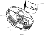
- FIG. 3 is a schematic structural diagram that the accommodating appliance and the automatic cleaning device are not assembled together provided by some embodiments of the present disclosure.
- the automatic cleaning device 100 further includes a first fan 160, and the first fan 160 is not shown in the figure since it is located inside the automatic cleaning device 100.
- the first fan 160 is configured to provide a wind suction power source to generate an air flow when the automatic cleaning device 100 executes the cleaning work.
- the garbage enters the frame 112 through the wind vent 1121, and is then collected into the accommodating appliance of the automatic cleaning device 100.
- the automatic cleaning device 100 has an accommodating space 150.
- the accommodating space 150 is configured to accommodate the accommodating appliance.
- the side wall of the accommodating space 150 is provided with a second opening 151 and an air vent 152, and the second opening 151 and the air vent 152 are both communicated with the outside.
- the garbage enters the accommodating appliance through the wind vent 1121 and the second opening 151.
- the air vent 152 is configured to allow outside air to enter the accommodating appliance through the air vent 152 when the automatic cleaning device 100 returns to the dust collection charging pile 200 for a dust collection operation.
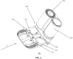
- FIG. 4 is a schematic structural diagram of a dust collection charging pile provided by some embodiments of the present disclosure.
- the dust collection charging pile 200 integrates a charging pile and a dust collection pile, and is configured to provide energy supply and garbage collection for the automatic cleaning device 100.
- the dust collection charging pile 200 includes a dust collection charging pile base 210 and a dust collection charging main body 220.
- the dust collection charging main body 220 is configured to charge the automatic cleaning device 100 and collect the garbage in the accommodating appliance of the automatic cleaning device 100, and is arranged on the dust collection charging pile base 210.
- the dust collection charging main body 220 includes a dust collection container 222, and a dust collection fan 223, also called a second fan 223.
- the dust collection container 222 is, for example, in the form of a cylinder, and is configured to collect the garbage in the accommodating appliance of the automatic cleaning device 100.
- the second fan 223 is connected to a wind outlet of the dust collection container 222, so as to provide power for collecting the garbage in the accommodating appliance of the automatic cleaning device 100 into the dust collection container 222.
- the dust collection charging pile 200 includes a charging connector 221 configured to supply energy to the automatic cleaning device 100, and a dust suction port 211 configured to be engaged with a dust outlet of the automatic cleaning device 100 (when the automatic cleaning device 100 discharges dust into the dust collection charging pile 200, the wind vent 1121 in the automatic cleaning device 100 serves as the dust outlet), and the garbage in the accommodating appliance of the automatic cleaning device 100 enters the dust collection container 222 of the dust collection charging main body 220 through the dust suction port 211.
- the charging connector 221 is arranged on the dust collection charging main body 220, and the dust suction port 211 is arranged on the dust collection charging pile base 210.
- a sealing rubber pad 214 is further arranged around the dust suction port 211 for sealing the dust suction port 211 engaged with the dust outlet of the automatic cleaning device 100 to prevent the garbage from leaking.
- a wind inlet of the dust collection container 222 is communicated with the dust suction port 211 through a dust collection wind path 215.
- the garbage contained in the accommodating appliance in the automatic cleaning device 100 can be collected in the dust collection container 222 through the wind vent 1121 in the automatic cleaning device 100 via the dust collection wind path 215.
- FIG. 5 is a schematic diagram of a scenario after the automatic cleaning device returns to the dust collection charging pile provided by some embodiments of the present disclosure.
- the automatic cleaning device 100 such as a sweeping robot
- the automatic cleaning device 100 will move onto the dust collection charging pile base 210 in the first direction X shown in FIG.
- FIG. 6 is a schematic diagram of an explosion structure of the accommodating appliance provided by some embodiments of the present disclosure
- FIG. 7 is a schematic structural diagram of a box body of the accommodating appliance in FIG. 6
- FIG. 8 is a schematic structural diagram of the box body in FIG. 7 from another perspective.
- the accommodating appliance 300 includes a box body 310 and a top cover 320.
- the box body 310 and the top cover 320 are non-detachably connected, to improve the sealing performance of the box body 310.
- the box body is matched with the accommodating space 150 and configured to provide a garbage storage function and a water storage function for the automatic cleaning device.
- the box body has a regular shape or an irregular shape, as long as it is adaptive to the accommodating space.
- the box body is in a shape similar to a right-angled trapezoid, and the hypotenuse of the right-angled trapezoid is replaced by an arc.
- the space can be fully utilized, and it is convenient to arrange other components to match the whole contour shape of the automatic cleaning device.
- the box body 310 includes a bottom wall 311 and side walls arranged around edges of the bottom wall 311.
- the side walls extend in a direction distal from the bottom wall 311, and the bottom wall 311 and the side walls enclose an accommodating space 312.
- the box body further includes a partition wall 316, and the partition wall 316 divides the accommodating space 312 into a dust box space 3121 and a water tank space 3122.
- the bottom of the box body is provided with an open corner-missing space 313, and part of the bottom wall of the box body 310 and the side walls connected to the part of bottom wall are recessed inward along the direction where the accommodating space is located, so as form the corner-missing space 313.
- the corner-missing space provides a space for arranging the one-way valve assembly, which avoids the interference between the one-way valve assembly and the accommodating space 150, and also avoids the interference between the one-way valve assembly and a water pipe in the water tank space.
- corner-missing space provides freedom of choice for the arranging position of the one-way valve assembly, and accordingly, the position and the opening direction of the one-way valve assembly can be better arranged, so that the air flow enters more smoothly, and the direction of the air flow is closer to the side walls of the dust box space, which is beneficial to rolling up all dust and avoiding omission.
- the corner-missing space 313 is located at the position where a vertex angle of the cuboid is missing, and includes a first side wall 3131, a fourth side wall 3132 and a top wall 3133. It can be understood that the corner-missing space 313 is enclosed by the first side wall, the fourth side wall and the top wall.
- the corner-missing space 313 is adjacent to the dust box space through the first side wall of the corner-missing space, and is adjacent to the water tank space 3122 through the fourth side wall 3132 and the top wall 3133.
- the side walls of the box body include a second side wall 314 and a third side wall 315.
- the second side wall 314 is adjacent to the first side wall 3131
- the third side wall 315 is adjacent to the second side wall 314, and the first side wall 3131 is arranged opposite to the third side wall 315.
- the second side wall 314 is provided with a first opening 3141.
- the first opening 3141 is sealedly engaged with the second opening 151, and the corner-missing space is communicated with the air vent 152.
- the first opening 3141 is a through hole, and the through hole is a passage that allows the garbage to enter or move out of the accommodating space 312.
- the garbage enters the dust box space 3121 through the first opening 3141.
- the garbage is moved out of the dust box space 3121 through the first opening 3141.
- the partition wall 316 extends from the bottom wall 311 of the box body towards the top cover 320, and divides the accommodation space into the dust box space 3121 and the water tank space 3122, thereby achieving the integrated functions of the dust box and the water tank in the same appliance.
- a cleaning frequency of the dust box is higher than a water adding frequency of the water tank, the dust box and water tank integrated accommodating appliance with the duct collection function can significantly reduce the taking-out frequency of the accommodating appliance and avoid the problem of cumbersome operations.
- the dust box space and the water tank space are arranged in parallel in the direction parallel to the bottom wall of the box body.
- the water tank space semi-surrounds the dust box space.
- the first side wall 3131 forms part of the partition wall 316
- one end portion of the partition wall 316 is connected to the second side wall 314, and the other end portion of the partition wall 316 is connected to the approximate end portion of the third side wall 315 distal from the second side wall 314.
- water is heavier than dust
- the water tank space is distributed in the whole transverse space of the box body, so that the stability of the automatic cleaning device is improved.
- the shape of the partition wall 316 is not limited, as long as the accommodating space can be divided into the two parts of spaces.
- the partition wall 316 is flaky and irregular, which can ensure that the dust box space is relatively regular and the volume is maximized while ensuring that the accommodating space is divided into the two parts of spaces. Further, an auxiliary guiding role for the air flow entering the dust box space can be achieved, and a flow direction of the air flow is guided. Therefore, it is easier to roll up and discharge the dust by arranging the partition wall having the specific shape.
- the partition wall 316 includes a first sub-partition wall 3161 parallel to the third side wall 315, a second sub-partition wall 3162 parallel to the second side wall 314, a third sub-partition wall 3163 connected to the first sub-partition wall and the second side wall, and a fourth sub-partition wall 3164 connected to the first sub-partition wall and the second sub-partition wall, wherein the fourth sub-partition wall extends from the end portion of the second side wall to the direction of the end portion of the third side wall, and a certain included angle is formed between the fourth sub-partition wall and each of the directions of the second side wall and the third side wall.
- the third sub-partition wall divides the first opening from the air vent, and the one-way valve assembly 340 is arranged on the first sub-partition wall.
- the third sub-partition wall, the first sub-partition wall, the fourth sub-partition wall, the second sub-partition wall, the third side wall and the second side wall are sequentially connected to enclosed the dust box space.
- the one-way valve assembly 340 is in an open state, and the air flow entering from the one-way valve assembly 340 walks obliquely along the fourth sub-partition wall, so that a vortex can be formed more easily and more quickly to bring up all the dust, which is more effective than a square corner partition wall.
- the one-way valve assembly 340 is arranged on the first side wall of the corner-missing space. When the one-way valve assembly is in the closed state, the corner-missing space and the dust box space are isolated from each other. When the one-way valve assembly is switched from the closed state to the open state, the corner-missing space and the dust box space are communicated with each other.
- the external acting force is, for example, a suction force generated when the first fan 160 of the automatic cleaning device 100 and/or the second fan 223 in the dust collection charging pile 200 are/is in a working state.
- the threshold value is a critical value of the external acting force required to be provided when the one-way valve assembly 340 is switched from the closed state to the open state.
- the power of the first fan 160 of the automatic cleaning device 100 is obviously smaller than that of the second fan 223 in the suction force dust collection charging pile 200, that is, the suction force generated by the first fan 160 during working is obviously smaller than the suction force generated by the second fan 223.
- the suction force generated by the first fan 160 during working is smaller than the threshold value, and the one-way valve assembly 340 is in the closed state. Under the action of the air flow generated by the first fan 160, the garbage enters the frame 112 through the wind vent 1121, and is then collected into the dust box space 3121 of the automatic cleaning device 100.
- the automatic cleaning device 100 When the automatic cleaning device 100 returns to the dust collection charging pile 200 to dock with the dust collection charging pile 200, for collecting the garbage in the dust box space 3121 to the dust collection container 222 in the dust collection charging pile 200. Specifically, the automatic cleaning device 100 moves onto the dust collection charging pile base 210 in the first direction X, so that the dust outlet, namely, the wind vent 1121, of the automatic cleaning device 100 is sealedly engaged with the dust suction port 211 of the dust collection charging pile 200. The second fan 223 in the dust collection pile is in a working state. Under the action of the suction force generated by the second fan 223, the one-way valve assembly 340 is switched from the closed state to the open state.
- the one-way valve assembly 340 forms the wind inlet in the dust box space 3121, i.e., the wind inlet of the whole air flow channel, so that the air flow transfers the dust and other garbage in the dust box space 3121 into the dust collection container 222 in the dust collection charging pile 200.
- the first fan 160 in the automatic cleaning device 100 is also in a working state while the second fan 223 works to generate a strong suction force, which avoids reverse rotation of the first fan 160 in the automatic cleaning device 100 caused by the strong suction force generated by the second fan and further avoids damage to the first fan 160.
- the first fan and the second fan work simultaneously to generate an external acting force, greater than the threshold value, applied to the one-way valve assembly 340, the one-way valve assembly 340 is in the open state, and the strong air flow generated by the second fan 223 with greater power carries the garbage in the dust box space 3121 to be collected in the dust collection container 222 in the dust collection charging pile 200.
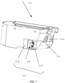
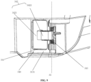
- FIG. 9 is a schematic structural diagram of the one-way valve assembly in FIG. 7 .
- the one-way valve assembly 340 includes a dust collection air opening 341, a valve component 342 and an elastic component 343.
- the dust collection air opening 341 is formed in the first side wall 3131, and for example, is a rectangular opening.
- the valve component 342 is configured to abut against the edge of the dust collection air opening to close the dust collection air opening 341 in response to the one-way valve assembly 340 being in the closed state.
- the valve component 342 In response to the one-way valve assembly 340 being in the open state, the valve component 342 is separated from at least part of the edge of the dust collection air opening 341, so that the air flow can enter the accommodating space 312 through the dust collection air opening 341.
- the elastic component 343 is connected to the valve component 342, and configured to abut the valve component 342 at the position of closing the dust collection air opening 341.
- the valve component 342 includes a plate-like structure 3421 and a pivoting portion 3422 connected to the plate-like structure 3421.
- the plate-like structure 3421 is, for example, rectangular and its size is slightly larger than that of the dust collection air opening 341.
- the plate-like structure 3421 closely adheres to the edge of the dust collection air opening 341 from the inside of the dust box space outwardly, so that the dust collection air opening 341 can be sealed.
- the plate-like structure 3421 can move towards the interior of the dust box space, so that the plate-like structure 3421 is separated from at least part of the edge of the dust collection air opening 341, and then the air flow can enter the dust box space through the dust collection air opening 341.
- the pivoting portion 3422 is of a similar T-shaped structure, and is pivotally connected to the outer surface of the first side wall 3131.
- the pivoting portion 3422 can rotate around a pivoting axis AX relative to the first side wall 3131, and the pivoting axis AX extends, for example, in a direction substantially perpendicular to the bottom wall 311, so that the pivoting portion 3422 can rotate in a plane substantially parallel to the bottom wall 311.
- the end portion of the pivoting portion 3422 distal from the pivoting axis AX is fixedly connected to the plate-like structure 3421, so that the valve component 342 can rotate around the pivoting axis AX as a whole.
- the elastic component 343, such as a spring, is connected to the pivoting portion 3422 in a matching manner, and the valve component 342 is abutted against the position of closing the dust collection air opening under the action of elasticity.
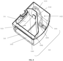
- FIG. 10 is a schematic structural diagram of a box body on which a filter mesh assembly is mounted provided by some embodiments of the present disclosure.
- the third side wall 315 of the box body is provided with a filter mesh mounting opening 3151.
- the accommodating appliance 300 further includes a filter mesh assembly 330.
- the filter mesh assembly 330 is detachably arranged at the filter mesh mounting opening 3151, and is arranged opposite to the first fan 160 of the automatic cleaning device.
- the filter mesh assembly 330 is, for example, a substantially rectangular plate.
- the top wall 3133 of the corner-missing space is provided with a water outlet assembly 350 configured to enable water stored in the water tank space to flow out of the accommodating appliance.
- the water outlet assembly includes a water outlet 351, a water outlet nozzle 352 and a sealing member (not shown in the figure).
- the water outlet 351 is formed in the top wall of the corner-missing space, and the water outlet nozzle 352 is mounted at the water outlet for providing a water source for mop cloth of the automatic cleaning device.
- the sealing member is arranged at the water outlet to prevent water leakage at the water outlet.
- a water pumping nozzle 360 is also arranged in the water tank space, and is communicated with the water outlet assembly 350 through a connecting pipe 370, and is used for pumping water in the water tank space and conveying the water to the water outlet nozzle through the connecting pipe to provide the water source.
- the top cover 320 is matched with the box body 310 and configured to cover the top of the accommodating space 312.
- the top cover 320 and the box body 310 are designed separately, or for another example, may be pivotally connected through one side wall, so that the accommodating appliance 300 can be switched between an open state and a closed state.
- the top cover 320 is connected to the box body 310 in a non-detachable manner to improve the sealing performance of the box body 310.
- the top cover 320 is provided with a water injection port 321, and an orthogonal projection of the water tank space on the top cover covers the water injection port 321.
- the accommodating appliance 300 also includes a water injection plug 322 detachably mounted at the water injection port 321 of the top cover and configured to seal the water injection port.
- the water injection plug is a switch of the water injection port 321. The water injection plug is opened when water injection is needed, and is closed after water injection is completed.
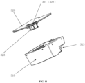
- FIG. 11 is a schematic diagram of an explosion structure of the accommodating appliance according to some embodiments of the present disclosure.
- the accommodating appliance further includes: a water tank filter mesh 323 detachably mounted on one side of the top cover facing the box body and located at the water injection port, and an orthogonal projection of the water tank filter mesh on the top cover covers the water injection port.
- the water tank filter mesh 323 is of a cuboid hollow structure, and water enters the water tank filter mesh through the water injection port.
- the water tank filter mesh is used to filter impurities in the injected water, and the filtered water is stored in the water tank space so as to be used by the mop cloth in work.
- the accommodating appliance further includes a one-way air valve opening 324.
- the one-way air valve opening 324 is formed on the top cover 320, and an orthogonal projection of the water tank space on the top cover covers the one-way air valve opening 324.
- the one-way air valve opening 324 is used to arrange a one-way air valve to keep air pressure in the water tank consistent with the atmospheric pressure during water pumping.
- the accommodating appliance 300 is mounted in the accommodating space 150 of the automatic cleaning device 100, and the first fan 160 of the automatic cleaning device 100 is opposite to the filter mesh assembly of the dust box space 3121, so as to draw the air flow from the dust box space 3121 through the filter mesh assembly.
- the wind vent 1121 of the automatic cleaning device 100 is communicated with the first opening 3141 of the dust box space 3121, and the wind vent 1121 and the first opening 3141 provide a passage for the garbage to enter or move out of the automatic cleaning device 100.
- the first fan 160 works to generate the external acting force applied to the one-way valve assembly, the external acting force is less than the threshold value, and the one-way valve assembly 60 is in the closed state.
- the air flow sequentially passes through the wind vent, the second opening, the first opening, the dust box space and the filter mesh assembly to form a complete first wind duct.
- the air flow carrying the garbage enters the dust box space 3121 from the wind vent 1121 of the automatic cleaning device 100 through the first opening 3141 of the dust box space 3121.
- the garbage is remained in the dust box space 3121, and the filtered air flow enters the automatic cleaning device and is discharged.
- the automatic cleaning device 100 When the automatic cleaning device is in the dust discharging mode, the automatic cleaning device 100 returns to the dust collection charging pile 200, and the dust suction port 211 of the dust collection charging pile 200 may serve as an inlet of the dust collection wind path 215, and is in sealed communication with the wind vent 1121 of the automatic cleaning device 100 located on the dust collection charging pile base 210, namely, the dust outlet of the automatic cleaning device 100.
- the wind inlet of the dust collection container 222 is in sealed communication with the outlet of the dust collection wind path 215, and the second fan 223 is connected to the wind outlet of the dust collection container 222.
- the external air flow sequentially passes through the air vent, the dust collection air opening, the dust box space, the first opening, the wind vent, the dust suction port and the dust collection wind path of the automatic cleaning device to form a second wind duct.
- the first fan 160 in the automatic cleaning device 100 is also in the working state.
- the external acting force applied to the one-way valve assembly 340 is greater than the threshold value, and the one-way valve assembly 340 is in the open state.
- the dust collection air opening 341 serves as the air inlet of the dust box space 3121, and most of the air flow carries the garbage in the dust box space 3121 under the strong suction force generated by the high-power second fan 223 and passes through the first opening 3141 of the dust box space 3121, the wind vent 1121 of the automatic cleaning device 100, the dust suction port 211 of the dust collection charging pile 200 and the dust collection wind path 215 to enter the dust collection container 222, and then the garbage is collected in the dust collection container 222. After the dust collection is finished, the first fan 160 and the second fan 223 stop working.
- the external acting force applied to the one-way valve assembly 340 may still be greater than the threshold value by relying on the strong suction force generated by the second fan 223, and the one-way valve assembly 340 is in the open state to ensure the smoothness of the whole air flow channel.
- the air flow will enter the dust box from the filter mesh assembly 330, the entering diameter of the air flow is generally increased, causing the insufficient air flow strength. As a result, it is difficult to blow up all the dust, which adversely affects the dust collection efficiency.
- the first fan 160 possibly reversely rotates under the strong suction force generated by the second fan 223, resulting in damage to the first fan 160.
- the working power of the first fan 160 in the automatic cleaning device 100 when the automatic cleaning device 100 is in the dust discharging mode is less than or equal to the working power of the first fan 160 when the automatic cleaning device 100 is in the cleaning working mode.
- the lower the working power of the first fan 160 in the automatic cleaning device 100 when the automatic cleaning device 100 is in the dust discharging mode the better, thereby reducing the power consumption in the whole process of collecting the garbage in the dust box into the dust collection container.
- the dust box and the water tank are integrated and move at the same time during disassembling and mounting, which solves the problem that a water tank and a dust box are required to be taken out and mounted separately in the related art and the operations are cumbersome.
- the accommodating appliance has the advantages of multiple functions, few parts, low cost, simple assembling, high space utilization rate and the like.
- the one-way valve assembly is arranged in the accommodating appliance, and a wind duct in the dust box space can be controlled by switching the one-way valve assembly between the closed state and the open state, so that the garbage in the dust box space is output to the outside under the action of a fluid in the wind duct, and the dust collection function is achieved.
Landscapes
- Filtering Of Dispersed Particles In Gases (AREA)
- Electric Suction Cleaners (AREA)
- Electric Vacuum Cleaner (AREA)
Applications Claiming Priority (2)
| Application Number | Priority Date | Filing Date | Title |
|---|---|---|---|
| CN202220024456.1U CN216932992U (zh) | 2022-01-05 | 2022-01-05 | 容置器具及自动清洁设备 |
| PCT/CN2022/089091 WO2023130623A1 (zh) | 2022-01-05 | 2022-04-25 | 容置器具及自动清洁设备 |
Publications (2)
| Publication Number | Publication Date |
|---|---|
| EP4454530A1 true EP4454530A1 (de) | 2024-10-30 |
| EP4454530A4 EP4454530A4 (de) | 2026-01-07 |
Family
ID=82313911
Family Applications (1)
| Application Number | Title | Priority Date | Filing Date |
|---|---|---|---|
| EP22918087.2A Pending EP4454530A4 (de) | 2022-01-05 | 2022-04-25 | Aufnahmevorrichtung und automatische reinigungsvorrichtung |
Country Status (7)
| Country | Link |
|---|---|
| US (1) | US20250089974A1 (de) |
| EP (1) | EP4454530A4 (de) |
| JP (1) | JP7760740B2 (de) |
| KR (1) | KR20240132045A (de) |
| CN (1) | CN216932992U (de) |
| AU (1) | AU2022430778B2 (de) |
| WO (1) | WO2023130623A1 (de) |
Families Citing this family (4)
| Publication number | Priority date | Publication date | Assignee | Title |
|---|---|---|---|---|
| USD1122861S1 (en) * | 2022-06-02 | 2026-04-21 | Samsung Electronics Co., Ltd. | Charger for vacuum cleaner |
| CN115813285A (zh) * | 2022-08-02 | 2023-03-21 | 深圳银星智能集团股份有限公司 | 清洁机器和清洁系统 |
| CN116998963A (zh) * | 2023-08-25 | 2023-11-07 | 北京石头世纪科技股份有限公司 | 一种容置器具、自移动清洁设备及自移动清洁系统 |
| CN116998962A (zh) * | 2023-08-25 | 2023-11-07 | 北京石头世纪科技股份有限公司 | 一种集尘盒、自移动清洁设备及系统 |
Family Cites Families (14)
| Publication number | Priority date | Publication date | Assignee | Title |
|---|---|---|---|---|
| GB245462A (de) * | 1924-12-31 | 1926-05-04 | Paul Breton | |
| US5408721A (en) * | 1993-12-27 | 1995-04-25 | Wall; James C. | Automatic dustpan member for central vacuum cleaning system |
| JP4205466B2 (ja) * | 2003-03-20 | 2009-01-07 | 日立アプライアンス株式会社 | 電気掃除機 |
| CN207186582U (zh) * | 2017-01-05 | 2018-04-06 | 科沃斯机器人股份有限公司 | 一体式尘盒水箱及其地面清洁机器人 |
| CN209346902U (zh) * | 2018-11-14 | 2019-09-06 | 广东乐生智能科技有限公司 | 一种扫地机器人及其一体式水箱尘盒 |
| CN119769950A (zh) * | 2020-01-22 | 2025-04-08 | 帝舍智能科技(武汉)有限公司 | 水槽及自清洁拖扫机 |
| JP2021194152A (ja) * | 2020-06-11 | 2021-12-27 | パナソニックIpマネジメント株式会社 | 掃除機システム、自律走行型掃除機、保持装置、及び制御装置 |
| CN112022007B (zh) * | 2020-09-07 | 2022-10-21 | 追觅创新科技(苏州)有限公司 | 扫地机器人的尘盒清洁控制方法、装置及存储介质 |
| CN214208244U (zh) * | 2020-09-07 | 2021-09-17 | 追觅创新科技(苏州)有限公司 | 智能清洁系统 |
| CN112369971B (zh) * | 2020-12-05 | 2025-06-10 | 曲阜信多达智能科技有限公司 | 一种尘盒及其清洁机器人系统 |
| CN112401765B (zh) * | 2020-12-05 | 2024-08-06 | 曲阜信多达智能科技有限公司 | 一种清洁机器人系统的控制方法 |
| CN112971634A (zh) * | 2021-02-26 | 2021-06-18 | 北京享捷科技有限公司 | 一种扫地机器人的集成箱体 |
| CN112914440A (zh) * | 2021-03-24 | 2021-06-08 | 北京享捷科技有限公司 | 一种扫地机器人 |
| CN113303721A (zh) * | 2021-06-29 | 2021-08-27 | 东莞芯速科技有限公司 | 一种适配集尘桶的集尘盒与水箱一体式结构及扫地机器人 |
-
2022
- 2022-01-05 CN CN202220024456.1U patent/CN216932992U/zh active Active
- 2022-04-25 WO PCT/CN2022/089091 patent/WO2023130623A1/zh not_active Ceased
- 2022-04-25 JP JP2024540796A patent/JP7760740B2/ja active Active
- 2022-04-25 KR KR1020247025703A patent/KR20240132045A/ko active Pending
- 2022-04-25 AU AU2022430778A patent/AU2022430778B2/en active Active
- 2022-04-25 EP EP22918087.2A patent/EP4454530A4/de active Pending
- 2022-04-25 US US18/726,940 patent/US20250089974A1/en active Pending
Also Published As
| Publication number | Publication date |
|---|---|
| AU2022430778B2 (en) | 2025-12-11 |
| WO2023130623A1 (zh) | 2023-07-13 |
| EP4454530A4 (de) | 2026-01-07 |
| CN216932992U (zh) | 2022-07-12 |
| JP7760740B2 (ja) | 2025-10-27 |
| US20250089974A1 (en) | 2025-03-20 |
| JP2025501353A (ja) | 2025-01-17 |
| AU2022430778A1 (en) | 2024-08-22 |
| KR20240132045A (ko) | 2024-09-02 |
Similar Documents
| Publication | Publication Date | Title |
|---|---|---|
| EP4454530A1 (de) | Aufnahmevorrichtung und automatische reinigungsvorrichtung | |
| EP4364626A1 (de) | Staubbox, automatische reinigungsvorrichtung und staubsammeldock | |
| KR20070074147A (ko) | 청소기 시스템 | |
| EP4159102A1 (de) | Müllbehälteranordnung, reinigungsroboter und system dafür | |
| US8661611B2 (en) | Dust collector for a vacuum cleaner having a filtered dust removal function and vacuum cleaner | |
| JP2007181656A (ja) | 掃除機システム | |
| CN218934778U (zh) | 清洁设备的风机装置、维护基站及清洁机器人系统 | |
| WO2023143074A1 (zh) | 一种洗地机 | |
| CN112515532A (zh) | 尘盒组件、清洁机器人和清洁系统 | |
| WO2025044595A1 (zh) | 容置器具、自移动清洁设备及自移动清洁系统 | |
| CN216602768U (zh) | 一种清洁基站以及清洁系统 | |
| CN221242685U (zh) | 尘杯组件、清洁设备、基站及清洁系统 | |
| CN221105746U (zh) | 集尘盒、扫地机及清洁设备 | |
| KR100411432B1 (ko) | 합체형 진공 청소기 | |
| CN222787660U (zh) | 清洁设备、基站及清洁系统 | |
| CN216854569U (zh) | 尘盒、自动清洁设备以及集尘桩 | |
| US20250064288A1 (en) | Self-cleaning dust collection base and dust collection system | |
| US20230210332A1 (en) | Cleaning robot and cleaning machine system | |
| US20230165421A1 (en) | Cleaning Robot and Robot System | |
| CN213588175U (zh) | 智能清洁系统 | |
| CN118105008A (zh) | 抽吸装置、基站以及清洁服务系统 | |
| CN223453169U (zh) | 清洁系统、清洁服务站及清洁机器人 | |
| CN220344318U (zh) | 一种集尘装置、清洁机器人和清洁机器人工作站 | |
| CN116493338A (zh) | 清洁装置及终端设备的产线系统 | |
| AU2024326264A1 (en) | Cleaning apparatus and cleaning system |
Legal Events
| Date | Code | Title | Description |
|---|---|---|---|
| STAA | Information on the status of an ep patent application or granted ep patent |
Free format text: STATUS: THE INTERNATIONAL PUBLICATION HAS BEEN MADE |
|
| PUAI | Public reference made under article 153(3) epc to a published international application that has entered the european phase |
Free format text: ORIGINAL CODE: 0009012 |
|
| STAA | Information on the status of an ep patent application or granted ep patent |
Free format text: STATUS: REQUEST FOR EXAMINATION WAS MADE |
|
| 17P | Request for examination filed |
Effective date: 20240725 |
|
| AK | Designated contracting states |
Kind code of ref document: A1 Designated state(s): AL AT BE BG CH CY CZ DE DK EE ES FI FR GB GR HR HU IE IS IT LI LT LU LV MC MK MT NL NO PL PT RO RS SE SI SK SM TR |
|
| DAV | Request for validation of the european patent (deleted) | ||
| DAX | Request for extension of the european patent (deleted) | ||
| REG | Reference to a national code |
Ref country code: DE Ref legal event code: R079 Free format text: PREVIOUS MAIN CLASS: A47L0011240000 Ipc: A47L0011400000 |
|
| A4 | Supplementary search report drawn up and despatched |
Effective date: 20251205 |
|
| RIC1 | Information provided on ipc code assigned before grant |
Ipc: A47L 11/40 20060101AFI20251201BHEP |