EP4451816A1 - Submodul - Google Patents
Submodul Download PDFInfo
- Publication number
- EP4451816A1 EP4451816A1 EP22907734.2A EP22907734A EP4451816A1 EP 4451816 A1 EP4451816 A1 EP 4451816A1 EP 22907734 A EP22907734 A EP 22907734A EP 4451816 A1 EP4451816 A1 EP 4451816A1
- Authority
- EP
- European Patent Office
- Prior art keywords
- enclosure
- heat sink
- submodule
- opening
- terminal
- Prior art date
- Legal status (The legal status is an assumption and is not a legal conclusion. Google has not performed a legal analysis and makes no representation as to the accuracy of the status listed.)
- Pending
Links
Images



Classifications
-
- H—ELECTRICITY
- H05—ELECTRIC TECHNIQUES NOT OTHERWISE PROVIDED FOR
- H05K—PRINTED CIRCUITS; CASINGS OR CONSTRUCTIONAL DETAILS OF ELECTRIC APPARATUS; MANUFACTURE OF ASSEMBLAGES OF ELECTRICAL COMPONENTS
- H05K7/00—Constructional details common to different types of electric apparatus
- H05K7/20—Modifications to facilitate cooling, ventilating, or heating
- H05K7/2089—Modifications to facilitate cooling, ventilating, or heating for power electronics, e.g. for inverters for controlling motor
- H05K7/209—Heat transfer by conduction from internal heat source to heat radiating structure
-
- H—ELECTRICITY
- H02—GENERATION; CONVERSION OR DISTRIBUTION OF ELECTRIC POWER
- H02M—APPARATUS FOR CONVERSION BETWEEN AC AND AC, BETWEEN AC AND DC, OR BETWEEN DC AND DC, AND FOR USE WITH MAINS OR SIMILAR POWER SUPPLY SYSTEMS; CONVERSION OF DC OR AC INPUT POWER INTO SURGE OUTPUT POWER; CONTROL OR REGULATION THEREOF
- H02M7/00—Conversion of AC power input into DC power output; Conversion of DC power input into AC power output
-
- H—ELECTRICITY
- H02—GENERATION; CONVERSION OR DISTRIBUTION OF ELECTRIC POWER
- H02M—APPARATUS FOR CONVERSION BETWEEN AC AND AC, BETWEEN AC AND DC, OR BETWEEN DC AND DC, AND FOR USE WITH MAINS OR SIMILAR POWER SUPPLY SYSTEMS; CONVERSION OF DC OR AC INPUT POWER INTO SURGE OUTPUT POWER; CONTROL OR REGULATION THEREOF
- H02M7/00—Conversion of AC power input into DC power output; Conversion of DC power input into AC power output
- H02M7/003—Constructional details, e.g. physical layout, assembly, wiring or busbar connections
-
- H—ELECTRICITY
- H05—ELECTRIC TECHNIQUES NOT OTHERWISE PROVIDED FOR
- H05K—PRINTED CIRCUITS; CASINGS OR CONSTRUCTIONAL DETAILS OF ELECTRIC APPARATUS; MANUFACTURE OF ASSEMBLAGES OF ELECTRICAL COMPONENTS
- H05K7/00—Constructional details common to different types of electric apparatus
- H05K7/14—Mounting supporting structure in casing or on frame or rack
- H05K7/1422—Printed circuit boards receptacles, e.g. stacked structures, electronic circuit modules or box like frames
- H05K7/1427—Housings
- H05K7/1432—Housings specially adapted for power drive units or power converters
- H05K7/14339—Housings specially adapted for power drive units or power converters specially adapted for high voltage operation
-
- H—ELECTRICITY
- H05—ELECTRIC TECHNIQUES NOT OTHERWISE PROVIDED FOR
- H05K—PRINTED CIRCUITS; CASINGS OR CONSTRUCTIONAL DETAILS OF ELECTRIC APPARATUS; MANUFACTURE OF ASSEMBLAGES OF ELECTRICAL COMPONENTS
- H05K7/00—Constructional details common to different types of electric apparatus
- H05K7/20—Modifications to facilitate cooling, ventilating, or heating
- H05K7/2039—Modifications to facilitate cooling, ventilating, or heating characterised by the heat transfer by conduction from the heat generating element to a dissipating body
- H05K7/20409—Outer radiating structures on heat dissipating housings, e.g. fins integrated with the housing
- H05K7/20418—Outer radiating structures on heat dissipating housings, e.g. fins integrated with the housing the radiating structures being additional and fastened onto the housing
-
- H—ELECTRICITY
- H05—ELECTRIC TECHNIQUES NOT OTHERWISE PROVIDED FOR
- H05K—PRINTED CIRCUITS; CASINGS OR CONSTRUCTIONAL DETAILS OF ELECTRIC APPARATUS; MANUFACTURE OF ASSEMBLAGES OF ELECTRICAL COMPONENTS
- H05K7/00—Constructional details common to different types of electric apparatus
- H05K7/20—Modifications to facilitate cooling, ventilating, or heating
- H05K7/2089—Modifications to facilitate cooling, ventilating, or heating for power electronics, e.g. for inverters for controlling motor
- H05K7/20927—Liquid coolant without phase change
Definitions
- the present disclosure relates to a submodule.
- the High Voltage Direct Current (HVDC) system is a power transmission method that uses direct current (DC) for electric power transmission.
- a power transmitting station converts AC power generated at a power plant into DC power and transmits the power, and a power receiving station reconverts it into AC power to supply.
- This transmission method uses direct current (DC) at high voltage levels, which reduces the losses compared to alternating current (AC) methods. It also improves the stability by separating the grids and avoids the inductive interference that affects long-distance power transmission.
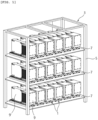
- a plurality of submodules 1 are installed in a frame 3 composed of a plurality of layers with a height of several meters.
- a plurality of partition plates 7 are installed to form a plurality of layers in a plurality of vertically installed columns 5.
- a plurality of submodules 1 are installed in rows on the partition plate 7.
- the submodule used in this system consist of a power supply unit 9 and a capacitor unit 9', and various power semiconductors and various control boards are installed in the power supply unit 9.
- the power semiconductor and control boards installed in the power supply unit 9 generate a lot of heat during operation.
- a heat dissipating device using cooling water is connected from the outside to the inside of the power supply unit 9. That is, there is a pipe for supplying cooling water to the inside of the power supply unit 9, which delivers the cooling water to a heat sink installed inside the power supply unit 9.
- Such a submodule 1 is used in a similar form not only in a High Voltage Direct Current system (HVDC system) but also in a Flexible Alternative Current Transmission system (FACT system) in which power semiconductors are used.
- HVDC system High Voltage Direct Current system
- FACT system Flexible Alternative Current Transmission system
- Prior arts related to the submodule described above include Korean Patent Registration No. 10-1623347 , Korean Patent Registration No. 10-1295070 , and Korean Patent Registration No. 10-1288679 .
- An object of the present disclosure is to reduce a size of a submodule.
- An object of the present disclosure is to prevent cooling water from entering the inside of a submodule.
- An object of the present disclosure is to simplify a connection structure between submodules.
- An object of the present disclosure is to facilitate heat dissipation to the outside while reducing a size of a submodule.
- a submodule of the present disclosure for achieving the above objects comprises: an enclosure in which parts are installed, and an opening is formed on one outer surface thereof; and a heat sink installed in the opening of the enclosure, having an inner surface inside the enclosure on which at least one of the parts installed, and the other surface being outside the enclosure.
- the opening may be formed in one of side plates of the enclosure to install the heat sink.
- the opening may be formed on a top plate of the enclosure to install the heat sink.
- the opening may be formed on a bottom plate of the enclosure to install the heat sink.
- a flow path through which cooling fluid flows is formed inside the heat sink, and the flow path may communicate with the outside through an inlet and an outlet installed at one side of the heat sink.
- a first terminal and a second terminal may be provided on the front plate of the enclosure to electrically connect to adjacent submodules.
- a first terminal for electrical connection with an adjacent submodule may be provided on the front plate of the enclosure, and a second terminal may be provided on the heat sink.
- a submodule comprises: an enclosure having a hexahedral shape in which parts are installed therein and an opening is formed on one outer surface thereof; and a heat sink installed in the opening of the enclosure, having an inner surface inside the enclosure on which at least one of the parts is installed, and the other surface is outside the enclosure.
- a flow path through which cooling fluid flows is formed inside the heat sink, and the flow path may communicate with the outside through an inlet and an outlet installed at one side of the heat sink.
- the opening may be formed in any one of a top plate, a side plate, and a bottom plate of the enclosure, and the heat sink may be installed to cover the opening to form one outer surface of the enclosure.
- a first terminal and a second terminal may be provided on a front plate of the enclosure to electrically connect to adjacent submodules.
- the first terminal for electrical connection with an adjacent submodule may be provided on the front plate of the enclosure, and the second terminal for electrical connection with an adjacent submodule may be provided on the heat sink.
- the submodule according to the present disclosure may have at least one or more of the following effects.
- a heat sink may constitute one surface of an enclosure constituting an exterior of a submodule. Therefore, since the heat sink constitutes one surface of the enclosure and does not occupy space inside the enclosure, space for installing the heat sink inside the enclosure of the submodule is not required, and the size of the enclosure may be reduced.
- the heat sink constitutes one outer surface of the enclosure, and one surface of the heat sink faces the inside of the enclosure and the other surface thereof is exposed to the outside of the enclosure.
- an inlet and an outlet for cooling fluid flowing in and out of the heat sink may be positioned on one side of the heat sink constituting one outer surface of the enclosure. This structure ensures that the cooling fluid does not enter the inside of the enclosure and does not affect parts installed inside the enclosure.
- the heat sink may be formed an outer surface of one side of the enclosure and the outer surface of the heat sink may be exposed to the outside. This means that heat may be dissipated more efficiently in the heat sink because heat exchange with the outside air may be performed more easily.
- a terminal for coupling a bus bar connecting adjacent submodules may be placed on the heat sink. This configuration allows the terminal to be integrally placed on one side of the heat sink, thereby reducing the number of parts as a whole.
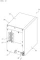
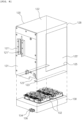
- FIGS. 2 and 3 shows a configuration of a submodule of the preferred embodiment of the present disclosure.
- An enclosure 20 may form an exterior of a submodule 10 of the present disclosure.
- the enclosure 20 forms the exterior of the submodule 20 and has a space therein where various parts may be installed.
- the enclosure 20 may have a hexahedral shape.
- a front plate 21 may form the front surface of the enclosure 20.
- a first terminal 21' and a second terminal 21" may be provided on the front plate 21.
- the first terminal 21' and the second terminal 21" may be electrically connected to the parts inside the enclosure 20.
- the first terminal 21' and the second terminal 21" may also be electrically connected to an adjacent submodule 10 through a connecting bus bar 40 (see FIG. 5 ).
- the front plate 21 may have configurations for external connection of the submodule 10 as well as configurations for manipulating the submodule 10.
- a top plate 22 may form an upper surface of the enclosure 20.
- the top plate 22 may be connected to an upper end of the front plate 21.
- the top plate 22 has a rectangular shape in this embodiment. However, the top plate 22 may have a different shape depending on the configuration of the enclosure 20.
- the bottom plate 23 may form the bottom of the enclosure 20.
- the bottom plate 23 may have the same shape and area as the top plate 22.
- Side plates 24 may be provided at both ends of the top plate 22 and the bottom plate 23 in the width direction.
- the side plates 24 may form both sides of the enclosure 20.
- One of the side plates 24 may have a first opening 25.
- the first opening 25 may allow the inside and outside of the enclosure 20 to communicate.
- a heat sink 30 to be described below may be installed to cover the first opening 25.
- the first opening 25 may be formed over the whole area or partial area of the side plate 24. In the illustrated embodiment, the opening 25 is formed over the whole area of the side plate 24.
- the other one of the side plate 24 may have a second opening 26.
- the second opening 26 is a part that an operator may access to the inside of the enclosure 20 for maintenance.
- the second opening 26 may be shielded by a cover 26'.
- the second opening 26 is formed over the whole area of the side plate 24.
- the second opening 26 may have an area and shape required for access to the inside of the enclosure 20.
- a plurality of louvers may be formed in the cover 26' to allow air to flow between the inside and outside of the enclosure 20.
- a third opening 28 may be formed on the rear surface of the enclosure 20 opposite to the front plate 21 in the enclosure 20.
- the third opening 28 may be formed over the whole area of the rear surface of the enclosure 20. However, the third opening 28 need not necessarily be formed over the whole rear surface of the enclosure 20.
- the third opening 28 may be formed only on a partial area of the rear surface of the enclosure 20. Through the third opening 28, a capacitor unit (not shown) and the parts inside the enclosure 20 may be connected.
- a heat sink 30 may be installed in the enclosure 20 to cover the first opening 25.
- the heat sink 30 may serve to discharge heat generated from the parts inside the enclosure 20 to the outside.
- the heat sink 30 may be made of a metal material.
- a power semiconductor 32 inside the enclosure 20 may be installed on an inner surface of the heat sink 30.
- An example of the power semiconductor 32 may be an IGBT.
- a control board (not shown) positioned inside the enclosure 20 may also be installed on the heat sink 30. Heating elements including the power semiconductor 32 may be installed on an inner surface of the heat sink 30. Of course, the heating elements may be located inside the enclosure 20 instead of the heat sink 30.
- One surface of the heat sink 30 faces the inside of the enclosure 20, and the other surface thereof is positioned outside of the enclosure 20 to be in contact with external air. Accordingly, the heat sink 30 may discharge heat generated inside the enclosure 20 to the outside of the enclosure 20.
- an inlet 34 and an outlet 36 may be installed in the heat sink 30, as shown in FIG. 2 .
- the inlet 34 and the outlet 36 transfer a cooling fluid such as cooling water.
- a pipe (not shown) supplying cooling fluid may be connected to the inlet 34 to transfer the cooling fluid to the inside of the heat sink 30.
- a pipe (not shown) may be connected to the outlet 36 to discharge the cooling fluid and transfer it to a configuration for heat dissipation.
- a flow path (not shown) communicating with the inlet 34 and the outlet 36 may be formed inside the heat sink 30. Cooling fluid may flow through the flow path while absorbing heat generated inside the enclosure 20.
- the flow path may be formed in a zigzag pattern inside the heat sink 30 to evenly absorb heat over the entire area of the heat sink 30.
- the thickness of the heat sink 30 is relatively thicker than the thickness of the front plate 21, the top plate 22, the bottom plate 23, and the side plate 24 constituting the enclosure 20. This is to allow a flow path for cooling fluid to be formed inside the heat sink 30.
- the heat sink 30 may be installed on the opposite side of the enclosure 20.
- the cover 26' may be installed in the first opening 25.
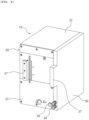
- FIGS. 4 and 5 another embodiment of the present disclosure is shown in FIGS. 4 and 5 .
- the overall configuration of the embodiment shown in FIGS. 4 and 5 is similar to that shown in FIG. 2 . Therefore, for convenience of description, the same reference numerals are assigned to the same configurations as those of the embodiment shown in FIG. 2 .
- a first terminal 21' may be installed on the front plate 21 constituting the front surface of the enclosure 20.
- a second terminal 37 may be provided on the heat sink 30 installed on the outer surface of the enclosure 20. The second terminal 37 may be integrally formed on one side of the heat sink 30.
- the second terminal 37 may be located at a predetermined height of the front edge of the heat sink 30 corresponding to the same height as the first terminal 21'.
- the first terminal 21' and the second terminal 37 may be located side by side at the same height from the bottom plate 23.
- the connecting bus bar 40 may be made of a metal plate.
- a bus bar body 41 may form the skeleton of the connecting bus bar 40.
- the bus bar body 41 may have a predetermined plate shape. In this embodiment, the bus bar body 41 is a rectangular plate.
- At both ends of the bus bar body 41 there may be a first coupling part 42 and a second coupling part 43 for coupling to the first terminal 21' and the second terminal 37.
- the first coupling part 42 and the second coupling part 43 may be coupled to the first terminal 21' and the second terminal 37 respectively by means of screws.
- the first coupling part 42 may be orthogonal to the bus bar body 41.
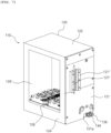
- FIGS.6 to 8 show another embodiment of the present disclosure.
- an enclosure 120 may form an exterior of a submodule 110.
- the enclosure 120 constitutes the exterior of the submodule 110 and has a space therein in which various parts may be installed.
- the enclosure 120 may have a hexahedral shape.
- a front plate 121 may form the front surface of the enclosure 120.
- a first terminal 121' and a second terminal 121" may be provided on the front plate 121.
- the first terminal 121' and the second terminal 121" may be electrically connected to the parts inside the enclosure 120.
- the first terminal 121' and the second terminal 121" may also be electrically connected to an adjacent submodule 110 through a connecting bus bar 40 (see FIG. 5 ) .
- the front plate 121 may have configurations for external connection of the submodule 110 as well as configurations for manipulating the submodule 110.
- a top plate 122 may form an upper surface of the enclosure 120.
- the top plate 122 may be connected to an upper end of the front plate 121.
- the top plate 122 has a rectangular shape in this embodiment. However, the top plate 122 may have a different shape depending on the configuration of the enclosure 120.
- On the opposite side of the top plate 122 there may be a bottom plate 123.
- the bottom plate 123 may form the bottom of the enclosure 120.
- the bottom plate 123 may have the same shape and area as the top plate 122.
- a bottom opening 123' may be formed in the bottom plate 123.
- the bottom opening 123' may be formed to occupy most of the area of the bottom plate 123.
- a heat sink 130 to be described below may be installed in the bottom opening 123' of the bottom plate 123.
- Side plates 124 may be provided at both ends of the top plate 122 and the bottom plate 123 in the width direction. The side plates 124 may form both sides of the enclosure 120.
- One of the side plates 124 may have a first opening 125.
- the first opening 125 may allow the inside and outside of the enclosure 120 to communicate.
- a heat sink 30 to be described below may be installed to cover the first opening 125.
- the first opening 125 may be formed over the whole area or partial area of the side plate 124. In the illustrated embodiment, the opening 125 is formed over the whole area of the side plate 124. Through the first opening 125, an operator may access the inside of the enclosure 120 for maintenance.
- the first opening 125 may have an area and shape required for an operator to access the inside of the enclosure 120.
- a first cover 125' may be installed in the first opening 125.
- the first cover 125' covers the first opening 125 so that the inner space of the enclosure 120 is not visible from the outside.
- a plurality of louvers may also be formed in the first cover 125'.
- the other one of the side plate 124 may have a second opening 126.
- the second opening 126 is a part that an operator may access to the inside of the enclosure 120 for maintenance.
- the second opening 126 may be shielded by a cover 126'.
- the second opening 126 is formed over the whole area of the side plate 124.
- the second opening 126 may have an area and shape required for access to the inside of the enclosure 120.
- a plurality of louvers may be formed in the cover 126' to allow air to flow between the inside and outside of the enclosure 120.
- first opening 125 and the second opening 126 are not necessary. Either one of the first opening 125 or the second opening 126 may be absent.
- a third opening 128 may be formed on the rear surface of the enclosure 120 opposite to the front plate 121 in the enclosure 120.
- the third opening 128 may be formed over the whole area of the rear surface of the enclosure 120.
- the third opening 28 need not necessarily be formed over the whole rear surface of the enclosure 120.
- the third opening 28 may be formed only on a partial area of the rear surface of the enclosure 120.
- a capacitor unit (not shown) and the parts inside the enclosure 120 may be connected.
- a heat sink 130 may be installed in the enclosure 120 to cover the bottom opening 123'.
- the heat sink 130 may serve to discharge heat generated from the parts inside the enclosure 120 to the outside.
- the heat sink 130 may be made of a metal material.
- a power semiconductor 132 inside the enclosure 20 may be installed on an inner surface of the heat sink 130.
- An example of the power semiconductor 132 may be an IGBT.
- a control board (not shown) positioned inside the enclosure 120 may also be installed on the heat sink 130. Heating elements including the power semiconductor 132 may be installed on an inner surface of the heat sink 30. Of course, the heating elements may be located inside the enclosure 120 instead of the heat sink 130.
- One surface of the heat sink 130 faces the inside of the enclosure 120, and the other surface thereof is positioned outside of the enclosure 120 to be in contact with external air. Accordingly, the heat sink 130 may discharge heat generated inside the enclosure 120 to the outside of the enclosure 120.
- an inlet 134 and an outlet 136 may be installed in the heat sink 130, as shown in FIG. 6 .
- the inlet 134 and the outlet 136 transfer a cooling fluid such as cooling water.
- a pipe (not shown) supplying cooling fluid may be connected to the inlet 134 to transfer the cooling fluid to the inside of the heat sink 130.
- a pipe (not shown) may be connected to the outlet 136 to discharge the cooling fluid and transfer it to a configuration for heat dissipation.
- a flow path (not shown) communicating with the inlet 134 and the outlet 136 may be formed inside the heat sink 130. Cooling fluid may flow through the flow path while absorbing heat generated inside the enclosure 120.
- the flow path may be formed in a zigzag pattern inside the heat sink 130 to evenly absorb heat over the entire area of the heat sink 130.
- the thickness of the heat sink 130 is relatively thicker than the thickness of the front plate 121, the top plate 122, the bottom plate 123, and the side plate 124 constituting the enclosure 120. This is to allow a flow path for cooling fluid to be formed inside the heat sink 130.
- An opening 121e may be formed at one side of the front plate 121 in order to prevent the inlet 134 and the outlet 136 of the heat sink 130 from interfering with the front plate 121.
- the opening 121e may be made by partially removing a lower edge of the front plate 121.
- the heat sinks 30 or 130 may be installed to be exposed on an outer surface of the enclosures 20 or 120. That is, the heat sink 30 or 130 may be installed on any one of the side plates 24 of the enclosure 20 or the bottom plate 123 of the enclosure 120.
- an opening may be formed in the top plate 22 or 122 of the enclosure 20 or 120 and the heat sink 30 or 130 may be installed therein.
- an opening may be formed in the front plate 21 or 121 and the heat sinks 30 or 130 may be installed therein.
- a plurality of the submodules 10 or 110 configured as described above are installed side by side on a partition plate forming a plurality of layers in a frame, and adjacent submodules 10 or 110 may be connected and used by a connecting bus bar 40.
- heat generated in the power semiconductors 32 or 132 may be conducted to the heat sink 30 or 130, one surface of which is exposed to the outside of the submodule 10 or 110, and the heat may be delivered to the cooling fluid flowing inside the heat sink 30 or 130.
- heat may also be radiated to the outside air through the outer surfaces of the heat sink 30 or 130.
- Cooling fluid flows into and out of the heat sink 30 or 130 through the inlet 34 or 134 and the outlet 36 or 136.
- the inlet 34 or 134 and the outlet 36 or 136 are connected to the heat sink 30 or 130 from the outside of the enclosures 20 or 120, with no access to the inside of the enclosures 20 or 120.
- the cooling fluid does not enter the inside of the enclosures 20 or 120, and the cooling fluid is not transferred to the parts inside the enclosures 20 or 120 due to leakage of the cooling fluid.
- the second terminal 37 when the second terminal 37 is placed on the heat sink 30, only the first terminal 21' may be installed on the front plate 21. That is, there is no need to install additional the second terminal 21" on the front plate 21, and the second terminal 37 integrally provided on the heat sink 30 is used to connect the adjacent submodule 10.
- the second terminal 37 is integrally formed with the heat sink 30, the number of the parts may be relatively reduced.
- the heat sink 30 or 130 is installed on one side plate 24 or the bottom plate 123 of the enclosure 20 or 120, but the heat sink 30 or 130 may be installed on the top plate 21 or 121 of the enclosures 20 and 120.
Landscapes
- Engineering & Computer Science (AREA)
- Microelectronics & Electronic Packaging (AREA)
- Physics & Mathematics (AREA)
- Thermal Sciences (AREA)
- Power Engineering (AREA)
- Cooling Or The Like Of Electrical Apparatus (AREA)
- Inverter Devices (AREA)
Applications Claiming Priority (2)
| Application Number | Priority Date | Filing Date | Title |
|---|---|---|---|
| KR1020210182004A KR102680888B1 (ko) | 2021-12-17 | 2021-12-17 | 서브모듈 |
| PCT/KR2022/018186 WO2023113264A1 (ko) | 2021-12-17 | 2022-11-17 | 서브모듈 |
Publications (2)
| Publication Number | Publication Date |
|---|---|
| EP4451816A1 true EP4451816A1 (de) | 2024-10-23 |
| EP4451816A4 EP4451816A4 (de) | 2026-04-29 |
Family
ID=86773003
Family Applications (1)
| Application Number | Title | Priority Date | Filing Date |
|---|---|---|---|
| EP22907734.2A Pending EP4451816A4 (de) | 2021-12-17 | 2022-11-17 | Submodul |
Country Status (5)
| Country | Link |
|---|---|
| US (1) | US20240276683A1 (de) |
| EP (1) | EP4451816A4 (de) |
| JP (1) | JP7799028B2 (de) |
| KR (2) | KR102680888B1 (de) |
| WO (1) | WO2023113264A1 (de) |
Family Cites Families (31)
| Publication number | Priority date | Publication date | Assignee | Title |
|---|---|---|---|---|
| DE3010363C2 (de) * | 1980-03-14 | 1987-02-12 | Siemens AG, 1000 Berlin und 8000 München | Gerätekombination für den Bergbau mit Bauelementen der Leistungselektronik |
| JPH0750863Y2 (ja) * | 1988-06-13 | 1995-11-15 | キヤノン株式会社 | 小型直流モータ |
| JP2873127B2 (ja) * | 1992-04-03 | 1999-03-24 | シャープ株式会社 | 正負安定化電源装置 |
| FR2771594B1 (fr) * | 1997-11-21 | 1999-12-31 | Schneider Electric Sa | Variateur electronique de vitesse |
| TWM240615U (en) * | 2003-03-17 | 2004-08-11 | Shuttle Inc | Combination structure of CPU heat dissipating device and power supply |
| US6999317B2 (en) * | 2003-08-12 | 2006-02-14 | Delphi Technologies, Inc. | Thermally enhanced electronic module with self-aligning heat sink |
| US20050225942A1 (en) * | 2004-04-07 | 2005-10-13 | First International Computer Inc. | Plug-in cooling device |
| US7251133B2 (en) * | 2004-11-29 | 2007-07-31 | Symbol Technologies, Inc. | Device with an external heat sink arrangement |
| KR100726003B1 (ko) * | 2007-03-07 | 2007-06-08 | 이상춘 | 절연식 방열판과 몰드형 에스씨알이 내장된 용접기용반도체모듈 키트 |
| US7817428B2 (en) * | 2008-06-27 | 2010-10-19 | Greer Jr David Randall | Enclosure with integrated heat wick |
| US8081463B2 (en) * | 2009-06-16 | 2011-12-20 | Asia Vital Components Co., Ltd. | Water-cooled communication chassis |
| JP5344182B2 (ja) | 2010-02-02 | 2013-11-20 | 株式会社安川電機 | 電力変換装置 |
| US9307674B2 (en) * | 2011-05-06 | 2016-04-05 | International Business Machines Corporation | Cooled electronic system with liquid-cooled cold plate and thermal spreader coupled to electronic component |
| DE102011076325B4 (de) * | 2011-05-24 | 2016-05-04 | Semikron Elektronik Gmbh & Co. Kg | Kühlanordnung für eine leistungselektronische Komponente mit Subsystemen und einer Kühleinrichtung |
| KR101288679B1 (ko) | 2012-04-13 | 2013-07-22 | 엘에스산전 주식회사 | Hvdc 시스템의 밸브 모듈 교체 장치 |
| KR101295070B1 (ko) | 2012-04-13 | 2013-08-08 | 엘에스산전 주식회사 | 초고압 직류송전시스템의 밸브모듈 적층구조 및 방법 |
| KR20140003080A (ko) * | 2012-06-29 | 2014-01-09 | 엘에스산전 주식회사 | 전력 장치의 냉각 시스템 |
| JP5789576B2 (ja) | 2012-09-14 | 2015-10-07 | 日立オートモティブシステムズ株式会社 | 電力変換装置 |
| JP5916673B2 (ja) * | 2013-08-25 | 2016-05-11 | 株式会社タムラ製作所 | 電源用回路モジュール及び電源用回路モジュール組立体 |
| CN104460917B (zh) | 2013-09-16 | 2017-10-17 | 康舒科技股份有限公司 | 服务器电源系统 |
| DE102013111018A1 (de) * | 2013-10-04 | 2015-04-09 | Abb Technology Ag | Trägerstruktur für Leistungselektronik |
| KR101546450B1 (ko) * | 2013-12-26 | 2015-08-27 | 주식회사 효성 | 초고압 직류 송전시스템의 모듈냉각장치 |
| KR101623347B1 (ko) | 2013-12-30 | 2016-06-07 | 주식회사 효성 | 초고압 직류 송전시스템의 모듈 인출장치 |
| JP6060266B2 (ja) * | 2015-04-28 | 2017-01-11 | 株式会社小松製作所 | 電子機器の冷却用筐体および電子機器並びに建設機械 |
| DE102018202484A1 (de) * | 2018-02-19 | 2019-08-22 | Zf Friedrichshafen Ag | Leistungselektronikanordnung |
| US10971873B2 (en) * | 2018-10-31 | 2021-04-06 | Lear Corporation | Electrical unit with cooling member |
| US11547024B2 (en) * | 2019-10-15 | 2023-01-03 | Lear Corporation | Electrical assembly |
| KR20200124451A (ko) * | 2019-04-24 | 2020-11-03 | 임명수 | 태양광 발전시스템의 밀폐형 접속반 방열장치 |
| KR102089892B1 (ko) * | 2019-05-03 | 2020-03-16 | 강대찬 | 에너지 저장장치 방열 케이스 |
| US11158998B1 (en) * | 2020-04-27 | 2021-10-26 | Abb Schweiz Ag | Heat sink for power supply panel |
| US11139639B1 (en) * | 2020-07-09 | 2021-10-05 | Ge Aviation Systems Limited | Modular power distribution assembly and method of assembly thereof |
-
2021
- 2021-12-17 KR KR1020210182004A patent/KR102680888B1/ko active Active
-
2022
- 2022-11-17 EP EP22907734.2A patent/EP4451816A4/de active Pending
- 2022-11-17 JP JP2024501688A patent/JP7799028B2/ja active Active
- 2022-11-17 US US18/569,200 patent/US20240276683A1/en active Pending
- 2022-11-17 WO PCT/KR2022/018186 patent/WO2023113264A1/ko not_active Ceased
-
2023
- 2023-11-14 KR KR1020230157537A patent/KR102834947B1/ko active Active
Also Published As
| Publication number | Publication date |
|---|---|
| KR102680888B1 (ko) | 2024-07-02 |
| EP4451816A4 (de) | 2026-04-29 |
| KR20230163318A (ko) | 2023-11-30 |
| JP7799028B2 (ja) | 2026-01-14 |
| US20240276683A1 (en) | 2024-08-15 |
| JP2024528817A (ja) | 2024-08-01 |
| KR20230092528A (ko) | 2023-06-26 |
| WO2023113264A1 (ko) | 2023-06-22 |
| KR102834947B1 (ko) | 2025-07-16 |
Similar Documents
| Publication | Publication Date | Title |
|---|---|---|
| CN120201684B (zh) | 一种功率设备及光伏系统 | |
| CN107078652B (zh) | 具有多部分式壳体和内部冷却空气通道的逆变器 | |
| EP2879476B1 (de) | Elektrische Vorrichtung | |
| CN110789379A (zh) | 用于给电动车辆充电的充电站 | |
| US10624243B2 (en) | Inverter for converting a DC voltage into an AC voltage | |
| EP3917300B1 (de) | Unterbrechungsfreie stromversorgung mit einer flüssigkeitskühlvorrichtung | |
| EP3493388B1 (de) | Stromwandlungsvorrichtung | |
| EP2061079A1 (de) | Halbleiterpaket und halbleiterpaketbaugruppe | |
| CN111525819B (zh) | 一种逆变器、逆变器与变压器的互连系统和箱式变电站 | |
| KR101254896B1 (ko) | 전원장치 | |
| CN105830550A (zh) | 用于高压直流传输系统的模块化冷却设备 | |
| EP4451816A1 (de) | Submodul | |
| CN219679064U (zh) | 一种防干扰散热结构及超声波装置 | |
| CN220476189U (zh) | 变流器及电气设备 | |
| CN110809384A (zh) | 一种散热装置及应用所述散热装置的电力设备 | |
| JP5684047B2 (ja) | 電気装置 | |
| CN113068377A (zh) | 一种发热器件散热结构、散热组件及电气设备 | |
| CN210328351U (zh) | 机柜及液冷变频器 | |
| CN213938680U (zh) | 散热装置及电子设备 | |
| KR102828225B1 (ko) | 절연 성능이 우수한 단일 패키징 타입 반도체 변압기용 서브모듈 | |
| CN115782636B (zh) | 充电模块及充电桩 | |
| CN111092540A (zh) | 电源装置 | |
| CN209948850U (zh) | 电机机壳 | |
| TWI912969B (zh) | 液冷式電源機箱及應用其之液冷式電源機櫃和資料中心冷卻系統 | |
| CN219514498U (zh) | 一种驱动散热器结构 |
Legal Events
| Date | Code | Title | Description |
|---|---|---|---|
| STAA | Information on the status of an ep patent application or granted ep patent |
Free format text: STATUS: THE INTERNATIONAL PUBLICATION HAS BEEN MADE |
|
| PUAI | Public reference made under article 153(3) epc to a published international application that has entered the european phase |
Free format text: ORIGINAL CODE: 0009012 |
|
| STAA | Information on the status of an ep patent application or granted ep patent |
Free format text: STATUS: REQUEST FOR EXAMINATION WAS MADE |
|
| 17P | Request for examination filed |
Effective date: 20231206 |
|
| AK | Designated contracting states |
Kind code of ref document: A1 Designated state(s): AL AT BE BG CH CY CZ DE DK EE ES FI FR GB GR HR HU IE IS IT LI LT LU LV MC ME MK MT NL NO PL PT RO RS SE SI SK SM TR |
|
| DAV | Request for validation of the european patent (deleted) | ||
| DAX | Request for extension of the european patent (deleted) | ||
| RIC1 | Information provided on ipc code assigned before grant |
Ipc: H05K 7/20 20060101AFI20251201BHEP Ipc: H02M 7/00 20060101ALI20251201BHEP Ipc: H05K 7/14 20060101ALI20251201BHEP |
|
| A4 | Supplementary search report drawn up and despatched |
Effective date: 20260327 |
|
| RIC1 | Information provided on ipc code assigned before grant |
Ipc: H05K 7/20 20060101AFI20260323BHEP Ipc: H02M 7/00 20060101ALI20260323BHEP Ipc: H05K 7/14 20060101ALI20260323BHEP |