EP4451802A1 - Système de cuisson, dispositif de plaque de cuisson, vaisselle de cuisson et procédé de fonctionnement d'un système de cuisson - Google Patents
Système de cuisson, dispositif de plaque de cuisson, vaisselle de cuisson et procédé de fonctionnement d'un système de cuisson Download PDFInfo
- Publication number
- EP4451802A1 EP4451802A1 EP24165590.1A EP24165590A EP4451802A1 EP 4451802 A1 EP4451802 A1 EP 4451802A1 EP 24165590 A EP24165590 A EP 24165590A EP 4451802 A1 EP4451802 A1 EP 4451802A1
- Authority
- EP
- European Patent Office
- Prior art keywords
- radiation
- unit
- receiving element
- food receiving
- cooking system
- Prior art date
- Legal status (The legal status is an assumption and is not a legal conclusion. Google has not performed a legal analysis and makes no representation as to the accuracy of the status listed.)
- Granted
Links
Images


Classifications
-
- H—ELECTRICITY
- H05—ELECTRIC TECHNIQUES NOT OTHERWISE PROVIDED FOR
- H05B—ELECTRIC HEATING; ELECTRIC LIGHT SOURCES NOT OTHERWISE PROVIDED FOR; CIRCUIT ARRANGEMENTS FOR ELECTRIC LIGHT SOURCES, IN GENERAL
- H05B6/00—Heating by electric, magnetic or electromagnetic fields
- H05B6/02—Induction heating
- H05B6/10—Induction heating apparatus, other than furnaces, for specific applications
- H05B6/12—Cooking devices
- H05B6/1209—Cooking devices induction cooking plates or the like and devices to be used in combination with them
Definitions
- the invention relates to a cooking system according to the preamble of claim 1, a hob device according to claim 12, a cooking utensil according to claim 13 and a method for operating the cooking system according to claim 14.
- An induction cooking system with an insulating base for thermal insulation of a base plate from cooking utensils and with a sensor unit for detecting the presence of the insulating base, for example by means of an RFID transponder in the insulating base, is already known from the prior art.
- the electronic components required for such an RFID system have poor heat resistance with regard to temperatures of 250°C to 300°C that can be reached on a surface of the base plate during certain cooking processes.
- heat resistance cannot be provided for the desired, particularly required, small dimensions of such an RFID transponder.
- the positioning of the base can only be detected inaccurately by the cooking system using the RFID system, which leads to low operational reliability.
- the object of the invention is in particular, but not limited to, providing a generic device with improved properties with regard to operational reliability and efficiency of the cooking system.
- the object is achieved according to the invention by the features of claims 1 and 14, while advantageous embodiments and further developments of the invention can be found in the subclaims.
- the invention is based on a cooking system, in particular an induction cooking system, with an insulation unit for thermally insulating a mounting plate from a food receiving element and with a sensor unit for determining a presence of the insulation unit between the mounting plate and the food receiving element.
- the sensor unit is provided for optically detecting the presence of the isolation unit.
- Such a design allows the presence of the insulation unit between the installation plate and the food receiving element to be determined particularly reliably, whereby in particular thermal damage to the installation plate can be advantageously avoided and operational reliability increased.
- an efficiency of the cooking system in particular a heating efficiency, can be increased by particularly reliably reducing or avoiding thermal losses due to heat transfer from the food receiving element to the installation plate.
- cost efficiency can be increased, in particular through high availability of corresponding components.
- a particularly flexible and/or simple design of the cooking system can be achieved, whereby in particular a determination efficiency can be increased.
- a complexity of the insulation unit can be advantageously reduced and in particular a heat resistance of the insulation unit can be advantageously increased.
- a "cooking system” is to be understood as a system which has at least the insulation unit and the sensor unit, and which can additionally have at least one hob device, preferably an induction hob device, and/or the installation plate and/or the food receiving element and/or a cooking utensil, in particular comprising the food receiving element, and which is in particular intended for carrying out at least one cooking process.
- the hob device can be designed at least as a part, in particular at least as a subassembly, of a hob, in particular an induction hob, wherein in particular accessory units for the hob can also be included in the hob device.
- the hob device in particular has at least one heating unit, which preferably has at least one heating coil, in particular an induction heating coil, and which is intended for heating the food receiving element.
- the hob device preferably has a plurality of heating units, which can also be arranged in the form of a matrix, for example, in particular in order to define a free cooking surface with a freely selectable installation position for cooking utensils.
- the hob device in particular can have a control unit at least for a control and/or regulation of the at least one heating unit.
- the hob device comprises in particular the sensor unit.
- the hob device is arranged in particular below the installation plate.
- the installation plate is preferably designed as a kitchen worktop.
- the installation plate can also be designed as a hob plate, in which case the hob device and the hob plate can be part of a hob or can form one.
- the installation plate can comprise any material or any combination of materials that appears to be appropriate to a person skilled in the art, or can consist of this material or this combination of materials.
- the installation plate could be made at least partially or at least to a large extent, in particular at least 55%, advantageously at least 65%, preferably at least 75%, particularly preferably at least 85% and particularly advantageously at least 95% of a volume and/or mass proportion of the installation plate, from glass and/or glass ceramic and/or from Neolith and/or from Dekton and/or from wood and/or from marble and/or from stone, in particular from natural stone and/or artificial stone, and/or from laminate and/or from metal and/or from plastic and/or from ceramic and/or from a composite material.
- the installation plate is preferably made from a non-metallic material.
- the installation plate prefferably has engravings and/or prints, in particular for marking at least one heating zone for heating the food receiving element.
- the installation plate is preferably free of engravings and/or prints.
- the installation plate is designed like a plate and in particular has a material thickness which preferably corresponds to a maximum of 50%, preferably a maximum of 20%, particularly preferably a maximum of 10%, and particularly advantageously a maximum of 5% of a length and/or a width of the element, wherein the installation plate in particular has opposite sides which have a flat, in particular smooth, surface.
- the installation plate has a fixed thickness.
- the installation plate is in particular intended for setting up the food receiving element and the insulation unit, in particular at least one cooking utensil, in particular a pot, a pan and/or the like, preferably for heating.
- the kitchen worktop in particular in contrast to the hob plate, is additionally intended to provide a food preparation area, in particular by, for example, cutting and/or mixing and/or mashing and/or peeling of food.
- the kitchen worktop is a piece of furniture, preferably a piece of kitchen furniture.
- the kitchen worktop is advantageously part of the kitchen and delimits and/or closes off in particular part of an assembly of kitchen cabinets and/or kitchen furniture and/or other household appliances, such as a dishwasher and/or a washing machine and/or an oven, at the top.
- the kitchen worktop it would also be conceivable for the kitchen worktop to be, for example, a kitchen worktop in a commercial kitchen and/or an outdoor cooking area. This makes it possible to achieve a high level of operating comfort, for example through advantageous use of the kitchen worktop outside of an operating state of the heating unit, and in particular an advantageous appearance of the cooking system.
- a particularly advantageous appearance can be achieved by making the installation plate, in particular the kitchen worktop or the hob plate, a kitchen floor and kitchen walls from similar materials.
- the temperatures reached on the surface of the installation plate during certain cooking processes can be high and in particular exceed 250°C.
- the material of the installation plate can have poorer thermal and mechanical properties than a conventional hob plate, in particular made of glass ceramic, whereby thermal damage, in particular due to uneven thermal expansion from heat concentrated on the heating zone of the installation plate originating from the food receiving element, can advantageously be avoided by the insulation unit. In particular, mechanical stresses which are higher than the breaking strength of the installation plate can advantageously be avoided.
- the food receiving element can be designed, for example, as at least one component of a pot and/or a pan and/or a roasting pan.
- the food receiving element can be arranged in a cooking surface area on the installation plate.
- the food receiving element is provided in particular for inductive heating, in particular by means of the heating unit.
- the insulation unit it would be conceivable for the insulation unit to be part of a cooking utensil which also comprises the food receiving element, wherein the insulation unit is arranged in particular below the food receiving element and is connected to it. This allows a particularly simple alignment of the food receiving element and the insulation unit in an installation state in which in particular the insulation unit is between the Installation plate and the food receiving element placed on the installation plate.
- the insulation unit can be forgotten simply by selecting unsuitable cooking utensils.
- the food receiving element prefferably, to be formed in one piece with the insulation unit.
- the term "in one piece” should be understood in particular to mean materially connected, such as by a welding process and/or adhesive process, etc., and particularly advantageously molded, such as by production from a cast and/or by production in a single or multi-component injection molding process.
- a material of the food receiving element differs at least partially from a material of the insulation unit, whereby in particular a heating efficiency of the food receiving element and a thermal insulation of the insulation unit can be advantageously increased.
- the food receiving element to be connected to the insulation unit in a force-fitting and/or form-fitting manner, such as by plug connections and/or rotary connections and/or screw connections.
- the insulation unit is designed separately from a cooking utensil that includes the food receiving element.
- the insulation unit is designed in particular to be separable from, and in particular movable relative to, the food receiving element, in particular the cooking utensil.
- the insulation unit is preferably designed as a base unit, in particular to be placed underneath the food receiving element when the food receiving element, in particular the cooking utensil, is placed on the installation plate.
- a connection between the food receiving element and the insulation unit is preferably provided only by placing the food receiving element on the insulation unit, in particular by gravity and/or a supporting force of the installation plate below the insulation unit.
- the insulation unit is preferably provided to provide a distance, which in particular corresponds to a thickness of the insulation unit, between the installation plate and the food receiving element.
- the insulation unit preferably has a thickness of at least 1 mm, preferably at least 2 mm, and particularly preferably at least 3 mm and/or a maximum of 10 mm, preferably at most 8 mm and particularly preferably at most 6 mm. It is conceivable that the insulation unit is designed as part of the cooking utensil as a plug and/or knobs and/or in a ring shape or the like, in particular on the food receiving element, wherein a volume between the installation plate and the food receiving element is preferably at least partially and preferably at least largely filled with air, whereby in particular thermal insulation can be effectively provided.
- the insulation unit is preferably at least partially and in particular at least to a large extent, in particular at least to at least 55%, advantageously at least 65%, preferably at least 75%, particularly preferably at least 85% and particularly advantageously at least 95% of a volume and/or mass fraction of the insulation unit, made of a thermally insulating material, for example glass fiber and/or silicone and/or aerogel and/or the like. It is conceivable that a volume between the support plate and the food receiving element is at least largely filled with the thermally insulating material of the insulation unit. This can provide particularly effective thermal insulation.
- the insulation unit can be designed in the form of a plate.
- the insulation unit is preferably homogeneous, in particular made of a homogeneous material. In particular, the insulation unit can be formed from just a single, continuous insulation element made of a homogeneous material.
- only one insulation unit is assigned to only one food receiving element.
- only one food receiving element is arranged on the insulation unit in the set-up state and only one insulation unit is arranged between the set-up plate and the one food receiving element.
- the cooking system can comprise at least one further insulation unit, which in the set-up state is preferably assigned to at least one further food receiving element, and in particular is intended for arrangement between the set-up plate and the further food receiving element of the cooking system.
- the insulation unit preferably has a Top side with a size that correlates to a size of an area of a bottom side of the food receiving element.
- the further insulation unit preferably has a further top side with a size that correlates to a size of an area of a further bottom side of the further food receiving element.
- more than one food receiving element is arranged on a single insulation unit or more than one insulation unit is arranged between the set-up plate and the one food receiving element.
- the sensor unit is at least intended to record at least one parameter and/or one physical property.
- the sensor unit preferably comprises at least one computing unit, in particular at least one microprocessor, and/or a memory unit, by means of which measured signals can be at least partially processed.
- the control unit it would be conceivable for the measured signals to be partially processed by the control unit.
- the control unit it would be conceivable for the control unit to have the computing unit and/or the memory unit.
- the cooking system in particular the hob device, preferably has at least one additional sensor unit, in particular for determining a temperature of the food receiving element.
- the additional sensor unit can detect the temperature in a known manner, for example by means of an IR temperature measurement.
- the additional sensor unit preferably has at least one IR radiation source and at least one IR radiation detector for detecting IR radiation reflected on the food receiving element and emitted by the IR radiation source.
- the installation plate preferably has a window and/or the insulation unit preferably has a window.
- the window of the installation plate and/or the window of the insulation unit is/are particularly permeable to at least a large extent to at least the IR radiation and the reflected IR radiation of the additional sensor unit, wherein the window of the installation plate and/or the insulation unit is/are particularly provided for a transmission of at least 55%, advantageously at least 65%, preferably at least 75%, particularly preferably at least 85% and particularly advantageously at least 95% of the IR radiation.
- the window of the mounting plate and/or the window of the insulation unit are designed for low-loss transmission of the IR radiation. This allows a temperature and/or a temperature profile of the food receiving element to be measured particularly efficiently by the additional sensor unit.
- the window of the support plate preferably extends at least partially along the normal direction of the support plate from a top side to a bottom side of the support plate and can be introduced into the support plate in particular by a suitable shaping process either directly during the manufacture of the support plate, for example by means of a suitable mold, or subsequently, for example by means of a drilling process or a milling process or the like.
- a "normal direction" of an object is to be understood as a direction which runs perpendicular to a main extension plane of the object.
- a "main extension plane" of a structural unit is to be understood as a plane which is parallel to a largest side surface of a smallest imaginary cuboid which just completely encloses the structural unit and in particular runs through the center of the cuboid.
- the window of the mounting plate and/or the insulation unit has a radiation transmission element.
- a radiation transmission element is to be understood as an element which is at least partially permeable to electromagnetic radiation and which transmits electromagnetic radiation at least in the longitudinal direction of the radiation transmission element. It is conceivable that the radiation transmission element at least partially prevents the entry and/or exit of at least electromagnetic radiation in directions aligned at least substantially perpendicular to the longitudinal direction of the radiation transmission element.
- the radiation transmission element has a temperature resistance of at least 250°C.
- the radiation transmission element could be made at least largely, in particular completely, from quartz. Alternatively or additionally, the radiation transmission element could have at least one thermoplastic material and in particular be made at least largely from such a material.
- the radiation transmission element could have at least one, in particular tubular, outer wall within which the electromagnetic radiation can run.
- the wall is intended to reflect electromagnetic radiation and comprises, for example, polished aluminum or a polished polymer which is coated with a PVD layer of aluminum.
- the window of the mounting plate and/or the insulation unit is/are designed as an opening which is in particular free of elements and/or units, in particular the radiation transmission element.
- the window of the installation plate is at least intended to enable a particularly low-loss transmission of visible light from a lighting unit of the cooking system, in particular the hob device, from an area below the installation plate to an area above the installation plate.
- the heating zone for heating the food receiving element could be made visible to an operator by means of the lighting unit.
- the window of the installation plate preferably forms a partial area of the installation plate, wherein the window of the installation plate can in particular have a diameter of a maximum of 10 cm, preferably at most 8 cm, preferably a maximum of 5 cm and particularly preferably a maximum of 2 cm and/or a minimum of 1 mm, preferably at least 5 mm and preferably at least 1 cm.
- the installation plate preferably has further windows, which are designed in particular analogously to the window of the installation plate and are each assigned to a further heating zone and/or the further heating unit.
- the window of the insulation unit preferably extends at least partially along a normal direction of the insulation unit and from a top side to a bottom side of the insulation unit.
- the normal direction of the insulation unit preferably runs parallel to the normal direction of the set-up plate.
- the cooking system preferably has further sensor units, which are designed in particular analogously to the sensor unit, which are each assigned in particular to a further heating zone and/or to the at least one further heating unit.
- the cooking system can also have further additional sensor units, which are designed in particular analogously to the additional sensor unit and which can each be assigned in particular to a further heating zone and/or to the further heating unit.
- the sensor unit is intended for optical determination, in particular for a determination, in particular a detection, in dependence on and/or using optical radiation.
- the cooking system has a heating unit, in particular the heating unit mentioned above, and a control unit, in particular the control unit mentioned above, which blocks or enables operation of the heating unit based on a signal from the sensor unit.
- the control unit is provided to block operation, in particular heating operation, of the heating unit for a determined absence, in particular a lack of presence, of the insulation unit between the installation plate and the food receiving element, in particular for an absence of the food receiving element and/or the insulation unit on the installation plate.
- the control unit is provided to transmit a notification signal, in particular an error signal and/or a warning signal, to the user at least for the determined absence of the insulation unit between the installation plate and the food receiving element.
- the notification signal could, for example, be displayed optically, in particular on a user interface.
- the control unit is particularly provided to enable operation of the heating unit for the determined presence of the insulation unit between the installation plate and the food receiving element. This ensures thermal insulation of the food receiving element with respect to the mounting plate for the operation of the heating unit, which in particular reliably provides increased heating efficiency and increased operational reliability.
- control unit is preferably provided for controlling and/or regulating the heating unit based on a signal from the additional sensor unit, whereby in particular operational reliability and/or ease of use can be further increased, in particular by at least partially automatic regulation of an advantageous temperature of the food receiving element and/or by blocking operation of the heating unit if the temperature of the food receiving element is estimated to be too high.
- the sensor unit is particularly designed for optical measurement of at least one sensor signal.
- the sensor unit is designed to compare a sensor characteristic derived from the measured sensor signal, in particular calculated by the computing unit, with at least one corresponding, in particular stored, reference value.
- the control unit is preferably designed to control the heating unit depending on a result of a comparison of the sensor characteristic and the reference variable.
- the sensor parameter and the sensor signal are dependent in particular on a distance between the mounting plate and the food receiving element, and thus in particular on the presence of the insulation unit between the mounting plate and the food receiving element.
- the reference variable is preferably stored in the storage unit. It would be conceivable for the reference variable to be stored in the storage unit before the cooking system is assembled. Alternatively, it would be conceivable for the reference variable to be set and/or calculated and stored by means of an input from an operator and/or an installer. Preferably, however, the sensor unit is provided for determining the reference variable for a calibration operation, in particular carried out by an installer and/or an operator, wherein the cooking system is in particular already assembled for the calibration operation. This allows the reference variable to be advantageously adapted to boundary conditions of the cooking system, in particular, for example, to a thickness of the installation plate and/or to a distance of the sensor unit from the installation plate and/or to a thickness of the insulation unit. Preferably, the sensor unit is provided for determining the reference variable in the installation state.
- the sensor unit is provided for optically determining a distance, in particular the above-mentioned distance, between the installation plate, in particular an upper side of the installation plate, and the food receiving element, in particular an underside of the food receiving element, whereby the presence of the insulation unit between the installation plate and the food receiving element can advantageously be determined in a particularly simple manner.
- the distance between the installation plate and the food receiving element in the installed state corresponds to the thickness of the insulation unit.
- the distance between the installation plate and the food receiving element can preferably be determined as a function of the measured sensor signal and in particular can be calculated by the computing unit.
- the sensor unit preferably has an uncertainty of at most 1 mm, preferably at most 0.7 mm, preferably at most 0.5 mm and particularly preferably at most 0.3 mm and particularly advantageously at most 0.1 mm.
- the sensor unit in particular the computing unit, is provided to compare the determined distance between the installation plate and the food receiving element with a reference distance.
- the sensor parameter corresponds to the determined distance between the installation plate and the food receiving element and the reference parameter corresponds to the reference distance.
- the reference distance preferably corresponds at least substantially to the thickness of the insulation unit, wherein the reference distance deviates from the thickness of the insulation unit in particular by less than 25%, preferably less than 10% and particularly preferably less than 5% from the thickness of the insulation unit.
- the reference distance corresponds to a smallest possible thickness of the insulation unit.
- the control unit is preferably designed to block the operation of the heating unit for the determined distance between the installation plate and the food receiving element less than the reference distance.
- the control unit is preferably designed to enable the operation of the heating unit for the determined distance between the installation plate and the food receiving element greater than or equal to the reference distance.
- the calibration operation can be provided for determining and in particular for storing at least one calculation value, in particular in the absence of the insulation unit between the installation plate and the food receiving element.
- the calculation unit is preferably provided for calculating the distance between the installation plate and the food receiving element depending on the at least one calculation value.
- the sensor parameter differs from the distance between the mounting plate and the food receiving element.
- the sensor unit is provided for a direct comparison of the measured sensor signal with a corresponding reference value and in particular the control unit is provided for controlling the heating unit depending on a result of the comparison.
- the sensor unit has at least one radiation source for emitting radiation and at least one radiation detector for detecting reflected radiation, wherein the reflected radiation is detected by a reflection the radiation, in particular emitted by the radiation source, is provided on the food receiving element, in particular on an underside of the food receiving element.
- the optical detection of the sensor unit can be provided particularly efficiently and/or simply, in particular in that the food receiving element can advantageously be used as an optical component on which the reflection takes place.
- the underside of the food receiving element is preferably flat, whereby in particular an advantageous and in particular particularly controllable reflection can be provided.
- the radiation source is particularly intended to emit radiation in the form of optical radiation.
- Optical radiation is to be understood in particular as radiation from a sub-range of the electromagnetic spectrum, which includes ultraviolet radiation, in particular in a spectral range between 100 nm and 400 nm, visible radiation, in particular in a spectral range between 380 nm and 780 nm, and infrared radiation, in particular in a spectral range between 780 nm and 1 mm.
- the radiation emanating from the radiation source and/or the reflected radiation is visible radiation.
- the radiation source can comprise a red laser diode, in particular with a wavelength in a value range of 635 nm to 750 nm, whereby the cost efficiency of the sensor unit can be advantageously increased.
- the radiation detector is preferably a component, in particular an optoelectronic component, which is intended to convert an electromagnetic radiation, in particular optically reflected radiation, which is incident on it, into an electrical detection signal, preferably by utilizing the photoelectric effect.
- the radiation detector can have at least one photodiode for detecting the reflected radiation, which can be designed in particular as a PIN photodiode and/or as an avalanche photodiode and/or MSM photodiode.
- the radiation detector can also comprise, for example, a photocell and/or a photomultiplier and/or an active pixel sensor and/or a CCD sensor and/or a phototransistor and/or a photoresistor for detecting optical radiation, alternatively or in addition to a photodiode.
- the above-mentioned sensor parameter can, for example, correspond to a distance, in particular an optical path length, between the radiation source and the food receiving element and/or the food receiving element and the radiation detector.
- the above-mentioned calculation value can, for example, correspond to a distance, in particular an optical path length, between the radiation source and the upper side of the mounting plate and/or the upper side of the mounting plate and the radiation detector.
- the insulation unit has a window, in particular the above-mentioned window of the insulation unit, which is at least largely permeable to the radiation from the radiation source and/or to the radiation reflected on the food receiving element.
- a window in particular the above-mentioned window of the insulation unit, which is at least largely permeable to the radiation from the radiation source and/or to the radiation reflected on the food receiving element. This allows the radiation and the reflected radiation to be transported between the sensor unit and the food receiving element with particularly no loss, and in particular on a direct path.
- the window can be used advantageously for detection by means of the sensor unit and in particular additionally for detection by means of the additional sensor unit.
- the window of the insulation unit is preferably provided for a transmission of at least 55%, advantageously at least 65%, preferably at least 75%, particularly preferably at least 85% and particularly advantageously at least 95% of the radiation emanating from the radiation source and the reflected radiation.
- the window of the insulation unit is designed as an opening, whereby in particular a particularly efficient thermal insulation and/or a particularly light weight and/or an advantageous cost efficiency of the insulation unit and/or a particularly effective transmission of the radiation from the radiation source and the reflected radiation can be achieved.
- the sensor unit is preferably arranged at least partially beneath the installation plate.
- at least the radiation source and/or the radiation detector are arranged beneath the installation plate.
- the cooking system has the installation plate and the sensor unit, in particular the entire sensor unit, is arranged beneath the installation plate, whereby a particularly advantageous appearance and/or a particularly compact structure of the cooking system can be achieved.
- the sensor unit can be advantageously protected, for example, from food and/or liquids and/or other external influences.
- the sensor unit is at least partially, for example at least the computing unit and/or the storage unit and/or the like is arranged at least partially above the mounting plate and/or at least partially in a recess of the mounting plate.
- At least the radiation source and/or the radiation detector of the sensor unit are preferably arranged on an electronic circuit board of the cooking system below the installation plate.
- the IR radiation detector and/or the IR radiation source of the additional sensor unit are also arranged on the electronic circuit board below the installation plate.
- the installation plate has a window, in particular the above-mentioned window of the installation plate, which is at least largely permeable to the radiation from the radiation source and/or to the radiation reflected on the food receiving element. This allows the radiation and the reflected radiation to be transported between the sensor unit and the food receiving element with particularly no loss, and in particular on a direct path.
- the window of the installation plate can advantageously be used for detection by means of the sensor unit and by means of the additional sensor unit.
- the window of the installation plate is, in particular at least parallel to the normal direction of the installation plate, preferably intended for a transmission of at least 55%, advantageously at least 65%, preferably at least 75%, particularly preferably at least 85% and particularly advantageously at least 95% of the radiation emanating from the radiation source and the reflected radiation.
- the window of the installation plate is preferably formed from the radiation transmission element, whereby the installation plate can advantageously form a closed surface through which in particular no food and/or liquids and/or the like can pass.
- the sensor unit is arranged at least partially overlapping the window of the installation plate.
- the sensor unit is arranged at least partially overlapping the window of the installation plate with respect to the normal direction of the installation plate.
- the radiation source and/or the radiation detector is arranged overlapping the window of the installation plate.
- the window of the installation plate and/or the window of the insulation unit and/or a recess in the middle of the heating unit and/or the radiation source and/or the radiation detector, in particular with respect to the normal direction of the installation plate, and/or the underside of the food receiving element at least partially overlap, at least in the installed state.
- the radiation from the radiation source and the reflected radiation can be transported particularly loss-free and in particular along a particularly short and/or straight optical path between the sensor unit and the food receiving element, wherein in particular a blocking and/or a reduction in intensity of the radiation and the reflected radiation in the optical path between the sensor unit and the food receiving element can advantageously be reduced or prevented.
- the sensor unit is at least partially arranged, in particular at least the radiation source and/or the radiation detector, under and/or in the recess in the middle of the heating unit.
- the recess of the heating unit preferably extends along the normal direction of the installation plate from a top side to a bottom side of the heating unit. It would be conceivable for the cooking system to have a cooling unit at least for the sensor unit.
- the cooking system has at least one radiation guide element for guiding the radiation from the radiation source and/or the reflected radiation from the window of the installation plate to the sensor unit.
- the sensor unit is at least partially arranged, in particular at least the radiation source and the radiation detector, offset from the window of the installation plate at least in a viewing direction parallel to the normal direction of the installation plate, wherein at least the radiation source and the radiation detector are arranged along the viewing direction in particular without overlapping with respect to the window of the installation plate.
- the sensor unit is at least partially arranged, in particular at least the radiation source and the radiation detector, in a direction parallel to the main extension plane of the installation plate at a distance from the heating unit.
- the sensor unit can advantageously be arranged in an area under the installation plate. in which a lower temperature prevails with respect to a temperature in the immediate vicinity of the heating unit, in particular in the middle of the heating unit, and/or in the immediate vicinity of the heating zone.
- the sensor unit can be advantageously protected and/or a complexity of the cooking system can be reduced by the sensor unit being able to be designed free of a cooling unit, for example.
- the radiation guiding element is preferably an optical component which is provided in particular at least for radiation guidance, in particular for influencing a direction of propagation of the radiation from the radiation source and/or the reflected radiation.
- the radiation guiding element is preferably provided for changing the direction of propagation of the radiation and/or the reflected radiation.
- the change in direction preferably has an angle of 90° and is provided in particular between a first direction parallel to the main extension direction of the mounting plate and a second direction parallel to the normal direction of the mounting plate.
- the radiation guiding element is preferably designed as a mirror and/or as a prism and/or as a radiation transmission element.
- a radiation guiding element designed as a mirror can have a flat mirror surface with an angle of 45° to the first direction and the second direction.
- the radiation transmission element can be provided for a change in direction, for example by means of mirrored side surfaces or the like, and/or for maintaining a direction of propagation of the radiation from the radiation source and/or the reflected radiation. It is conceivable that the cooking system has more than one radiation guide element for guiding the radiation and/or the reflected radiation, whereby, for example, at least one radiation guide element could be provided for a change in direction and a further radiation guide element for maintaining the direction of propagation and in particular for shielding. At least by means of the further radiation guide element, in particular an influence of ambient radiation and/or an escape of the radiation from the radiation source and/or the reflected radiation at an undesirable position can be advantageously reduced or avoided.
- the cooking system only requires the radiation transmission element formed radiation element, which in particular is only intended to maintain the propagation direction of the radiation and/or the reflected radiation, wherein in this embodiment it is further conceivable that the radiation source and/or the radiation detector are arranged overlapping the window of the mounting plate, in particular at least with respect to the normal direction of the mounting plate.
- the additional sensor unit is arranged in the cooking system at a position analogous to the position of the sensor unit.
- the sensor unit has a laser meter, whereby the distance measurement can be provided in a particularly reliable and precise manner.
- the laser meter can have a precision of 0.1 mm for distance determination by the laser meter.
- the laser meter is preferably provided to determine the presence of the insulation unit between the mounting plate and the food receiving element, to determine a light travel time, in particular of the radiation emanating from the radiation source and the reflected radiation, and/or a measured phase shift, in particular between the radiation emanating from the sensor unit and the reflected radiation.
- the laser meter can be provided for another laser meter measuring method that appears sensible to the person skilled in the art and is particularly known.
- the laser meter is provided at least to determine an optical path length between the laser meter and the food receiving element.
- the above-mentioned sensor signal and/or the sensor characteristic could, for example, correspond to the light propagation time and/or phase shift.
- the laser meter preferably has at least the radiation source, in particular a laser, and/or the radiation detector and/or the computing unit at least partially.
- the sensor unit can be designed as the laser meter.
- the sensor unit has an optical position sensor, in particular a position sensitive detector.
- the radiation detector is preferably designed as the optical position sensor.
- the optical position sensor is provided in particular for determining a one- or two-dimensional position, in particular on the position sensor, of the incident reflected radiation.
- an angle and/or a propagation direction of the emission of the radiation by the radiation source is stored, in particular in the storage unit, and/or adjustable and/or recognizable by the sensor unit.
- the sensor unit with the optical position sensor is preferably provided for determining the presence of the insulation unit between the support plate and the food receiving element as a function of triangulation, in particular by determining an angle between the radiation from the radiation source and the reflected radiation.
- the radiation source has a laser.
- the radiation source has a light-emitting diode, in particular with at least one integrated optical lens, for the emission of the optical radiation, for which in particular a particularly advantageous cost efficiency of the radiation source can be achieved.
- the above-mentioned sensor signal and/or the sensor parameter could, for example, correspond to an angle of incidence of the reflected radiation and/or an angle between the radiation of the radiation source and the reflected radiation and/or a position of the reflected radiation on the position sensor and/or a distance of the reflected radiation on the position sensor to a reference point and/or the like.
- a method for operating a cooking system with an insulation unit, in particular mentioned above, for thermally insulating a mounting plate, in particular mentioned above, from a food receiving element, in particular mentioned above, is proposed, wherein a presence of the insulation unit between the installation plate and the food receiving element is determined at least partially automatically and the presence of the insulation unit is determined optically.
- the presence of the insulation unit can be detected particularly reliably, whereby in particular thermal damage to the installation plate can be advantageously avoided and operational reliability increased.
- the efficiency of the cooking system in particular heating efficiency, can be increased by particularly reliably reducing or avoiding thermal losses due to heat transfer from the food receiving element to the installation plate.
- cost efficiency can be increased, in particular through high availability of corresponding components.
- the partially automatic determination comprises in particular at least one manual step, for example an operator input at the start of heating operation of a heating unit, and at least one automatic step, for example an automatic determination of the presence of the insulation unit between the food receiving element and the installation plate following the operator input. It is conceivable that the presence of the isolation unit is determined fully automatically.
- the method preferably has a method step, in particular a detection step, in which a radiation source of a sensor unit, in particular one mentioned above, emits radiation and is reflected on an underside of the food receiving element, in particular at least in a set-up state or in a state in which the food receiving element is placed directly on the set-up plate.
- the reflected radiation is preferably detected in the detection step by a radiation detector of the sensor unit.
- the method has a further method step, in particular an evaluation step, which is arranged in particular after the detection step.
- a sensor characteristic in particular a distance between the set-up plate and the food receiving element, is calculated preferably as a function of a sensor signal from the radiation detector and/or the radiation source generated in the detection step, in particular by means of a computing unit of the sensor unit.
- the sensor parameter in particular the distance between the installation plate and the food receiving element, is compared in a further method step, in particular a calibration step, with a reference parameter, in particular a stored reference distance.
- the calibration step is preferably arranged after the evaluation step.
- the method preferably has a further method step, in particular an activation step, which is arranged after the calibration step. In the activation step, a heating unit of the cooking system is preferably activated depending on the result of the comparison in the calibration step.
- the adjustment step is arranged immediately after the detection step and in the adjustment step in particular the sensor signal is compared with the corresponding reference variable.
- the cooking system, the hob device, the cooking utensils and the method for operating the cooking system should not be limited to the application and embodiment described above.
- the cooking system, the hob device, the cooking utensils and the method for operating the cooking system can have a number of individual elements, components, units and method steps that differs from the number stated herein in order to fulfill a function described herein.
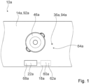
- FIG 1 shows a cooking system 10a in a schematic plan view.
- the cooking system 10a is designed as an induction cooking system.
- the cooking system 10a comprises a support plate 14a.
- the support plate 14a is intended for setting up at least one cooking utensil 46a of the cooking system 10a.
- the support plate 14a is designed as a kitchen worktop 92a.
- the support plate 14a could also be designed as a hob plate (not shown).
- the installation plate 14a has at least one heating zone 64a in which the cooking utensil 46a can be arranged in an installation state for heating.
- the cooking utensil 46a is designed here as a pot, for example.
- the cooking system 10a has a user interface 68a which is integrated in the support plate 14a.
- a user interface 68a By means of the user interface 68a, at least the heating of the cooking utensil 46a can be controlled and/or regulated by an operator.
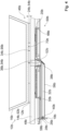
- FIG. 2 shows a section of the cooking system 10a in a set-up state in a schematic side view.
- the cooking system 10a has an insulation unit 12a for thermally insulating the set-up plate 14a from a food receiving element 16a.
- the insulation unit 12a is intended to provide a distance 24a, which corresponds to a thickness 54a of the insulation unit 12a, between the set-up plate 14a and the food receiving element 16a.
- the insulation unit 12a has a window 34a.
- the window 34a of the insulation unit 12a is arranged centered in the insulation unit 12a.
- the window 34a of the insulation unit 12a is designed as an opening 90a in the present case.
- the insulation unit 12a is made of a thermally insulating material.
- the insulation unit 12a is designed homogeneously. Alternatively, it would be conceivable for the window 34a of the insulation unit 12a to be designed as a radiation transmission element (not shown).
- the insulation unit 12a is designed in a ring shape in the present case.
- the food receiving element 16a is provided for inductive heating by a heating unit 20a.
- the food receiving element 16a is provided for receiving a food (not shown) at least for carrying out a cooking process.
- the food receiving element 16a is part of the cooking utensil 46a.
- the cooking utensil 46a has the food receiving element 16a and the insulation unit 12a, wherein the insulation unit 12a is arranged below the food receiving element 16a and is connected to the food receiving element 16a.
- the insulation unit 12a is designed as a base unit for the cooking utensil 46a, which is designed separately from the cooking utensil 46a.
- the cooking system 10a has the heating unit 20a.
- the heating unit 20a has a heating coil 66a for inductive heating of the food receiving element 16a.
- the heating unit 20a is arranged below the heating zone 64a (cf. Figure 1 ).
- the cooking system 10a has a sensor unit 18a for determining a presence of the insulation unit 12a between the installation plate 14a and the food receiving element 16a.
- the sensor unit 18a is provided at least for recording a physical quantity for determining a presence of the insulation unit 12a between the installation plate 14a and the food receiving element 16a.
- the support plate 14a has a window 36a.
- the window 36a of the support plate 14a is arranged in the heating zone 64a and can show an operator at least one position for the cooking utensil 46a on the support plate 14a for heating (cf. Figure 1 ).
- the window 36a of the installation plate 14a forms a center point of the heating zone 64a.
- the cooking utensil 46a is positioned on the window 36a of the installation plate 14a in the installation state.
- the window 34a of the installation plate 14a has a radiation transmission element 94a, in this case made of quartz.
- a lighting unit (not shown) of the cooking system 10a can be arranged below the window 36a of the installation plate 14a.
- an additional sensor unit 58a of the cooking system 10a is arranged below the window 36a of the installation plate 14a, which is intended for measuring the temperature of the cooking utensil 46a by means of IR radiation (not shown).
- the additional sensor unit 58a is intended for emitting the IR radiation and for detecting the IR radiation reflected on the food receiving element 16a.
- the window 36a of the mounting plate 14a and the window 34a of the insulation unit 12a are designed for low-loss transmission of at least the IR radiation provided.
- the additional sensor unit 58a is arranged on an electronic board 48a.
- the additional sensor unit 58a is arranged below a recess 52a of the heating unit 20a.
- the cooking system 10a has a hob device 50a, which has the sensor unit 18a.
- the hob device 50a is arranged below the installation plate 14a.
- the hob device 50a is assigned to the heating zone 64a.
- the hob device 50a is designed as an induction hob device.
- the hob device 50a has the heating unit 20a and, in this case, also at least the additional sensor unit 58a.
- the sensor unit 18a is provided for optically determining the presence of the insulation unit 12a.
- the sensor unit 18a is provided for optical determination in dependence on and using optical radiation.
- the cooking system 10a has a control unit 22a.
- the control unit 22a is integrated in the user interface 68a (see Figure 1 ).
- the control unit 22a is at least connected in terms of data to the sensor unit 18a (cf. Figure 1 ).
- the control unit 22a is provided to block or enable operation of the heating unit 20a based on a signal from the sensor unit 18a.
- the control unit 22a is provided to enable operation of the heating unit 20a for the detected presence of the insulation unit 12a between the food receiving element 16a and the mounting plate 14a.
- the control unit 22a is provided to block operation of the heating unit 20a for a detected absence of the insulation unit 12a between the food receiving element 16a and the mounting plate 14a.
- the sensor unit 18a is arranged under the mounting plate 14a.
- the sensor unit 18a has a computing unit 60a and a storage unit 62a (cf. Figure 1 ).
- the control unit 22a at least partially comprises the computing unit 60a and/or the memory unit 62a.
- the sensor unit 18a is provided for optically determining the distance 24a between the mounting plate 14a and the food receiving element 16a.
- the distance 24a between the mounting plate 14a and the food receiving element 16a can be determined depending on a sensor signal measured by the sensor unit 18a.
- the computing unit 60a is designed to calculate the distance 24a between the mounting plate 14a and the food receiving element 16a.
- the computing unit 60a is provided here to compare the determined distance 24a between the mounting plate 14a and the food receiving element 16a with a reference distance. The reference distance is stored in the storage unit 62a.
- the control unit 22a is provided in the present case for controlling the heating unit 20a depending on a comparison of the reference distance and the determined distance 24a between the support plate 14a and the food receiving element 16a.
- the sensor unit 18a has at least one radiation source 26a for emitting radiation 30a and at least one radiation detector 28a for detecting reflected radiation 32a, wherein the reflected radiation 32a is provided by a reflection of the radiation 30a from the radiation source 26a on the food receiving element 16a.
- the radiation source 26a is provided for emitting optical radiation 30a.
- the radiation detector 28a is provided for detecting optical reflected radiation 32a.
- the radiation source 26a is provided in the present case for emitting visible radiation 30a.
- the radiation detector 28a is provided in the present case for detecting visible reflected radiation 32a.
- the window 34a of the insulation unit 12a is at least largely permeable to the radiation 30a of the radiation source 26a and to the radiation 32a reflected by the food receiving element 16a.
- the window 36a of the mounting plate 14a is at least largely permeable to the radiation 30a of the radiation source 26a and/or to the radiation 32a reflected by the food receiving element 16a.
- the sensor unit 18a is arranged under the mounting plate 14a.
- the radiation source 26a and the radiation detector 28a of the sensor unit 18a are arranged on the electronic board 48a.
- the radiation source 26a and the radiation detector 28a of the sensor unit 18a are arranged below the recess 52a of the heating unit 20a.
- the sensor unit 18a is arranged at least partially overlapping with the window 36a of the mounting plate 14a. At least the radiation source 26a and the radiation detector 28a are arranged overlapping with the window 36a of the mounting plate 14a. The radiation source 26a and the radiation detector 28a additionally overlap with the window 34a of the insulation unit 12a and the recess 52a in the center of the heating unit 20a. The radiation source 26a and the radiation detector 28a overlap with the food receiving element 16a.
- the sensor unit 18a has an optical position sensor 42a.
- the optical position sensor 42a is designed as a position sensitive detector 44a.
- the radiation detector 28a has the optical position sensor 42a for detecting the reflected radiation 32a.
- the sensor unit 18a with the optical position sensor 42a is provided for determining the distance 24a between the support plate 14a and the food receiving element 16a for triangulation by means of the radiation 30a from the radiation source 26a and the reflected radiation 32a.
- the radiation source 26a here has a light-emitting diode with an integrated lens (not shown) for emitting the radiation 30a. Alternatively, it is conceivable that the radiation source 26a has a laser for emitting the radiation 30a.
- the sensor unit 18a has a laser meter (not shown) for determining the presence of the insulation unit 12a between the mounting plate 14a and the food receiving element 16a.
- Figure 3 shows a flow chart of a method for operating the cooking system 10a, wherein a presence of the insulation unit 12a between the installation plate 14a and the food receiving element 16a is determined at least partially automatically and optically.
- the method has a detection step 100a.
- the radiation source 26a emits the radiation 30a, which is reflected on an underside 70a of the food receiving element 16a in the set-up state or in a state in which the food receiving element 16a is placed directly on the set-up plate 14a.
- the reflected radiation 32a is detected by the radiation detector 28a in the detection step 100a.
- a distance 24a between the set-up plate 14a and the food receiving element 16a is calculated in the detection step 100a depending on a sensor signal from the radiation detector 28a and/or the radiation source 26a.
- the determined distance 24a is compared with a reference distance.
- the heating unit 20a is controlled depending on the result of the comparison in the adjustment step 104a.
- a cooking system 10b has a radiation guide element 38b for guiding radiation 30b from a radiation source 26b and for guiding reflected radiation 32b between a window 36b of a support plate 14b and a sensor unit 18b.
- the radiation guide element 38b is designed as a mirror.
- the radiation guide element 38b is provided for changing a propagation direction of the radiation 30b from the radiation source 26b and the reflected radiation 32b.
- the cooking system 10b has a further radiation guide element 56b designed as a radiation transmission element for guiding the radiation 30b from the radiation source 26b and the reflected radiation 32a.
- the further radiation guiding element 56b is provided at least to maintain the propagation direction of the radiation 30b emanating from the radiation source 26b and the reflected radiation 32b at least in the further radiation guiding element 56b.
- the sensor unit 18b has a laser meter 40b.
- the laser meter 40b has the radiation source 26b and a radiation detector 28b.
- the radiation source 26b is designed as a laser in the present case.
- the laser meter 40b has at least a partial computing unit (not shown).
- the laser meter 40b is intended for determining distances according to a known method.
Landscapes
- Physics & Mathematics (AREA)
- Electromagnetism (AREA)
- Electric Stoves And Ranges (AREA)
Applications Claiming Priority (1)
| Application Number | Priority Date | Filing Date | Title |
|---|---|---|---|
| EP23382373 | 2023-04-21 |
Publications (2)
| Publication Number | Publication Date |
|---|---|
| EP4451802A1 true EP4451802A1 (fr) | 2024-10-23 |
| EP4451802B1 EP4451802B1 (fr) | 2025-12-31 |
Family
ID=86185162
Family Applications (1)
| Application Number | Title | Priority Date | Filing Date |
|---|---|---|---|
| EP24165590.1A Active EP4451802B1 (fr) | 2023-04-21 | 2024-03-22 | Système de cuisson, dispositif de plaque de cuisson, vaisselle de cuisson et procédé de fonctionnement d'un système de cuisson |
Country Status (1)
| Country | Link |
|---|---|
| EP (1) | EP4451802B1 (fr) |
Cited By (1)
| Publication number | Priority date | Publication date | Assignee | Title |
|---|---|---|---|---|
| CN119960005A (zh) * | 2024-12-30 | 2025-05-09 | 中国核电工程有限公司 | 一种用于钚浓度测量的ZnS(Ag)闪烁体α计数仪装置 |
Citations (3)
| Publication number | Priority date | Publication date | Assignee | Title |
|---|---|---|---|---|
| US20180110364A1 (en) * | 2015-09-23 | 2018-04-26 | Lg Electronics Inc. | Container support |
| JP6425608B2 (ja) * | 2015-04-08 | 2018-11-21 | 三菱電機株式会社 | 温度検知装置および加熱調理器 |
| US20180352613A1 (en) * | 2015-12-17 | 2018-12-06 | BSH Hausgeräte GmbH | Pad device |
-
2024
- 2024-03-22 EP EP24165590.1A patent/EP4451802B1/fr active Active
Patent Citations (3)
| Publication number | Priority date | Publication date | Assignee | Title |
|---|---|---|---|---|
| JP6425608B2 (ja) * | 2015-04-08 | 2018-11-21 | 三菱電機株式会社 | 温度検知装置および加熱調理器 |
| US20180110364A1 (en) * | 2015-09-23 | 2018-04-26 | Lg Electronics Inc. | Container support |
| US20180352613A1 (en) * | 2015-12-17 | 2018-12-06 | BSH Hausgeräte GmbH | Pad device |
Cited By (1)
| Publication number | Priority date | Publication date | Assignee | Title |
|---|---|---|---|---|
| CN119960005A (zh) * | 2024-12-30 | 2025-05-09 | 中国核电工程有限公司 | 一种用于钚浓度测量的ZnS(Ag)闪烁体α计数仪装置 |
Also Published As
| Publication number | Publication date |
|---|---|
| EP4451802B1 (fr) | 2025-12-31 |
Similar Documents
| Publication | Publication Date | Title |
|---|---|---|
| DE102016101048B3 (de) | Glaskeramik-Kochmulde mit einem Infrarot-Sensor | |
| EP0690659B1 (fr) | Unité de cuisson à commande par infrarouge | |
| EP1704754B1 (fr) | Procede pour commander un processus de cuisson sur une table de cuisson et table de cuisson permettant de mettre en oeuvre ce procede | |
| EP4451802A1 (fr) | Système de cuisson, dispositif de plaque de cuisson, vaisselle de cuisson et procédé de fonctionnement d'un système de cuisson | |
| DE102004015255A1 (de) | Kochsensorik | |
| DE3717728A1 (de) | Kochplatte mit einer glaskeramikplatte | |
| EP2775792B1 (fr) | Appareil de cuisson | |
| EP3738407B1 (fr) | Système de table de cuisson | |
| DE102012200292A1 (de) | Bedieneinrichtung für ein Haushaltsgerät sowie Haushaltsgerät mit einer derartigen Bedieneinrichtung | |
| DE4422354A1 (de) | Infrarotgesteuerte Garungseinheit | |
| EP2775788B1 (fr) | Appareil de cuisson | |
| EP2775790B1 (fr) | Appareil de cuisson | |
| EP2775787B1 (fr) | Appareil de cuisson | |
| EP2775789B1 (fr) | Dispositif de cuisson et procédé de montage | |
| DE102024203613A1 (de) | Kochsystem, Kochfeldvorrichtung, Gargeschirr und Verfahren zu einem Betrieb eines Kochsystems | |
| EP2775786B1 (fr) | Appareil de cuisson | |
| DE102024203619A1 (de) | Kochsystem, Kochfeldvorrichtung, Gargeschirr und Verfahren zu einem Betrieb eines Kochsystems | |
| EP2704522A1 (fr) | Dispositif dýappareil ménager | |
| EP2703727A1 (fr) | Dispositif d'appareil ménager | |
| EP2594850B1 (fr) | Dispositif de commande pour un appareil ménager et appareil ménager doté d'un tel dispositif de commande | |
| WO2019048972A1 (fr) | Dispositif table de cuisson | |
| EP4699415A1 (fr) | Système de cuisson, dispositif de plan de cuisson, ustensile de cuisson et procédé de fonctionnement d'un système de cuisson | |
| EP2775791B1 (fr) | Appareil de cuisson | |
| WO2023203005A1 (fr) | Dispositif d'appareil électroménager et appareil électroménager | |
| DE102013102118A1 (de) | Kocheinrichtung und Verfahren zum Betreiben |
Legal Events
| Date | Code | Title | Description |
|---|---|---|---|
| PUAI | Public reference made under article 153(3) epc to a published international application that has entered the european phase |
Free format text: ORIGINAL CODE: 0009012 |
|
| STAA | Information on the status of an ep patent application or granted ep patent |
Free format text: STATUS: THE APPLICATION HAS BEEN PUBLISHED |
|
| AK | Designated contracting states |
Kind code of ref document: A1 Designated state(s): AL AT BE BG CH CY CZ DE DK EE ES FI FR GB GR HR HU IE IS IT LI LT LU LV MC ME MK MT NL NO PL PT RO RS SE SI SK SM TR |
|
| STAA | Information on the status of an ep patent application or granted ep patent |
Free format text: STATUS: REQUEST FOR EXAMINATION WAS MADE |
|
| 17P | Request for examination filed |
Effective date: 20250423 |
|
| GRAP | Despatch of communication of intention to grant a patent |
Free format text: ORIGINAL CODE: EPIDOSNIGR1 |
|
| STAA | Information on the status of an ep patent application or granted ep patent |
Free format text: STATUS: GRANT OF PATENT IS INTENDED |
|
| INTG | Intention to grant announced |
Effective date: 20250916 |
|
| GRAS | Grant fee paid |
Free format text: ORIGINAL CODE: EPIDOSNIGR3 |
|
| GRAA | (expected) grant |
Free format text: ORIGINAL CODE: 0009210 |
|
| STAA | Information on the status of an ep patent application or granted ep patent |
Free format text: STATUS: THE PATENT HAS BEEN GRANTED |
|
| AK | Designated contracting states |
Kind code of ref document: B1 Designated state(s): AL AT BE BG CH CY CZ DE DK EE ES FI FR GB GR HR HU IE IS IT LI LT LU LV MC ME MK MT NL NO PL PT RO RS SE SI SK SM TR |
|
| REG | Reference to a national code |
Ref country code: CH Ref legal event code: F10 Free format text: ST27 STATUS EVENT CODE: U-0-0-F10-F00 (AS PROVIDED BY THE NATIONAL OFFICE) Effective date: 20251231 Ref country code: GB Ref legal event code: FG4D Free format text: NOT ENGLISH |
|
| REG | Reference to a national code |
Ref country code: DE Ref legal event code: R096 Ref document number: 502024000566 Country of ref document: DE |
|
| REG | Reference to a national code |
Ref country code: IE Ref legal event code: FG4D Free format text: LANGUAGE OF EP DOCUMENT: GERMAN |
|
| REG | Reference to a national code |
Ref country code: LT Ref legal event code: MG9D |
|
| PG25 | Lapsed in a contracting state [announced via postgrant information from national office to epo] |
Ref country code: NO Free format text: LAPSE BECAUSE OF FAILURE TO SUBMIT A TRANSLATION OF THE DESCRIPTION OR TO PAY THE FEE WITHIN THE PRESCRIBED TIME-LIMIT Effective date: 20260331 |
|
| PGFP | Annual fee paid to national office [announced via postgrant information from national office to epo] |
Ref country code: DE Payment date: 20260331 Year of fee payment: 3 |
|
| PG25 | Lapsed in a contracting state [announced via postgrant information from national office to epo] |
Ref country code: HR Free format text: LAPSE BECAUSE OF FAILURE TO SUBMIT A TRANSLATION OF THE DESCRIPTION OR TO PAY THE FEE WITHIN THE PRESCRIBED TIME-LIMIT Effective date: 20251231 Ref country code: FI Free format text: LAPSE BECAUSE OF FAILURE TO SUBMIT A TRANSLATION OF THE DESCRIPTION OR TO PAY THE FEE WITHIN THE PRESCRIBED TIME-LIMIT Effective date: 20251231 |
|
| PGFP | Annual fee paid to national office [announced via postgrant information from national office to epo] |
Ref country code: AT Payment date: 20260301 Year of fee payment: 3 |
|
| PG25 | Lapsed in a contracting state [announced via postgrant information from national office to epo] |
Ref country code: RS Free format text: LAPSE BECAUSE OF FAILURE TO SUBMIT A TRANSLATION OF THE DESCRIPTION OR TO PAY THE FEE WITHIN THE PRESCRIBED TIME-LIMIT Effective date: 20260331 |