EP4451004A1 - Ansteuerungsvorrichtung für einen reflektierenden spiegel, ansteuerungsverfahren, radar und endgerät - Google Patents
Ansteuerungsvorrichtung für einen reflektierenden spiegel, ansteuerungsverfahren, radar und endgerät Download PDFInfo
- Publication number
- EP4451004A1 EP4451004A1 EP22917843.9A EP22917843A EP4451004A1 EP 4451004 A1 EP4451004 A1 EP 4451004A1 EP 22917843 A EP22917843 A EP 22917843A EP 4451004 A1 EP4451004 A1 EP 4451004A1
- Authority
- EP
- European Patent Office
- Prior art keywords
- reflecting mirror
- electromagnet
- power assisting
- assisting apparatus
- permanent magnet
- Prior art date
- Legal status (The legal status is an assumption and is not a legal conclusion. Google has not performed a legal analysis and makes no representation as to the accuracy of the status listed.)
- Pending
Links
Images



Classifications
-
- G—PHYSICS
- G01—MEASURING; TESTING
- G01S—RADIO DIRECTION-FINDING; RADIO NAVIGATION; DETERMINING DISTANCE OR VELOCITY BY USE OF RADIO WAVES; LOCATING OR PRESENCE-DETECTING BY USE OF THE REFLECTION OR RERADIATION OF RADIO WAVES; ANALOGOUS ARRANGEMENTS USING OTHER WAVES
- G01S7/00—Details of systems according to groups G01S13/00, G01S15/00, G01S17/00
- G01S7/48—Details of systems according to groups G01S13/00, G01S15/00, G01S17/00 of systems according to group G01S17/00
- G01S7/481—Constructional features, e.g. arrangements of optical elements
-
- G—PHYSICS
- G02—OPTICS
- G02B—OPTICAL ELEMENTS, SYSTEMS OR APPARATUS
- G02B26/00—Optical devices or arrangements for the control of light using movable or deformable optical elements
- G02B26/08—Optical devices or arrangements for the control of light using movable or deformable optical elements for controlling the direction of light
- G02B26/10—Scanning systems
- G02B26/105—Scanning systems with one or more pivoting mirrors or galvano-mirrors
-
- H—ELECTRICITY
- H04—ELECTRIC COMMUNICATION TECHNIQUE
- H04N—PICTORIAL COMMUNICATION, e.g. TELEVISION
- H04N3/00—Scanning details of television systems; Combination thereof with generation of supply voltages
- H04N3/02—Scanning details of television systems; Combination thereof with generation of supply voltages by optical-mechanical means only
- H04N3/08—Scanning details of television systems; Combination thereof with generation of supply voltages by optical-mechanical means only having a moving reflector
Definitions
- Embodiments of this application relate to the field of perception technologies, and more specifically, to a driving apparatus and a driving method of a reflecting mirror, a radar, and a terminal.
- a lidar (light detection and ranging, Lidar) reflecting mirror implements scanning coverage of a laser beam in space through reciprocating motion within a specific field of view (field of view, FOV).
- FOV field of view
- the reciprocating motion of the reflecting mirror needs to be driven by a driving component like a motor.
- acceleration motion and deceleration motion involved in the reciprocating motion of the reflecting mirror needs to be completed within a short time range to ensure lighting efficiency of the reflecting mirror. This undoubtedly imposes a higher requirement on the driving component like the motor.
- Embodiments of this application provide a driving apparatus and a driving method of a reflecting mirror, a radar, and a terminal, to reduce a requirement on a driving component like a motor.
- a driving apparatus of a reflecting mirror including a motor and a first power assisting apparatus.
- the motor is configured to drive the reflecting mirror to move.
- a first end of the first power assisting apparatus is fastened to a first end of the reflecting mirror, a second end of the first power assisting apparatus is fastened to a first position, the first position is fixed relative to the motor, and the first power assisting apparatus acts on the first end of the reflecting mirror for acceleration motion and/or deceleration motion.
- the motor in the driving apparatus may be alternatively replaced with another component having a drive function.
- the motor in the driving apparatus may be alternatively replaced with another component having a drive function.
- This is not limited in this application.
- the motor is used as an example.
- driving the reflecting mirror to move includes driving the reflecting mirror to perform reciprocating motion.
- the reflecting mirror performing the reciprocating motion may also be referred to as an oscillating mirror. This is not limited in this application. It should be understood that, in a process of performing the reciprocating motion, uniform motion, acceleration motion, and deceleration motion are involved.
- the first end of the reflecting mirror is mainly one of two ends that are of the reflecting mirror and that perform the reciprocating motion.
- the reflecting mirror one surface used to reflect a light beam is referred to as a front surface or a reflective surface, and the other surface is referred to as a back surface.
- the first end of the first power assisting apparatus may be fastened to the back surface of the first end of the reflecting mirror.
- the first position may be located on a housing of the motor, or may be another position fixed relative to the motor, provided that the first power assisting apparatus fastened to this position can assist the first end of the reflecting mirror in the acceleration motion and/or the deceleration motion.
- the first power assisting apparatus acts on the first end of the reflecting mirror for acceleration motion and/or deceleration motion mainly means that the first power assisting apparatus can assist the first end of the reflecting mirror in performing the acceleration motion and/or the deceleration motion.
- the driving apparatus of the reflecting mirror provided in embodiments of this application further includes the first power assisting apparatus, and the first power assisting apparatus can act on the first end of the reflecting mirror for the acceleration motion and/or the deceleration motion, to avoid a case in which the acceleration motion and/or the deceleration motion of the first end of the reflecting mirror are/is driven by only the motor. In this way, a requirement on the motor can be reduced.
- the first power assisting apparatus acts on the first end of the reflecting mirror for the acceleration motion and/or the deceleration motion may include: When the first end of the reflecting mirror performs the deceleration motion, a direction of a force applied to the first end of the reflecting mirror by the first power assisting apparatus is opposite to a moving direction of the first end of the reflecting mirror; and/or when the first end of the reflecting mirror performs the acceleration motion, the direction of the force applied to the first end of the reflecting mirror by the first power assisting apparatus is the same as the moving direction of the first end of the reflecting mirror.
- the direction of the force applied to the first end of the reflecting mirror by the first power assisting apparatus is opposite to the moving direction of the first end of the reflecting mirror, so that the first end of the reflecting mirror can be assisted in performing the deceleration motion.
- the direction of the force applied to the first end of the reflecting mirror by the first power assisting apparatus is the same as the moving direction of the first end of the reflecting mirror, so that the first end of the reflecting mirror can be assisted in performing the acceleration motion. In this way, the requirement on the motor can be reduced.
- the first power assisting apparatus includes a first spring.
- the first power assisting apparatus when the first power assisting apparatus includes the first spring, the first end of the reflecting mirror compresses or stretches the first spring during the reciprocating motion, to generate a pushing force or a pulling force on the first end of the reflecting mirror, so as to assist the first end of the reflecting mirror in the acceleration motion and/or the deceleration motion.
- the first end of the first power assisting apparatus includes a first permanent magnet
- the second end of the first power assisting apparatus includes a second permanent magnet
- an acting force generated between the first permanent magnet and the second permanent magnet is a repulsive force
- the repulsive force between the first permanent magnet and the second permanent magnet increases as a distance between the first permanent magnet and the second permanent magnet decreases, and decreases as the distance increases.
- the first end of the first power assisting apparatus includes a third permanent magnet
- the second end of the first power assisting apparatus includes a first electromagnet
- the permanent magnet in this application may be a magnet patch attached to the first end of the reflecting mirror or the first position, or may be a magnet block embedded in the first end of the reflecting mirror or the first position, or may be fastened to the first end of the reflecting mirror or the first position in another form. This is not limited in this application.
- the first power assisting apparatus is merely an example.
- the first end and the second end of the first power assisting apparatus each may include an electromagnet or a permanent magnet. This is not limited in this application.
- disposing an electromagnet at or embedding a magnet block in the first end of the reflecting mirror increases complexity of a manufacturing process of the first end of the reflecting mirror. Therefore, in this application, to simplify the manufacturing process of the first end of the reflecting mirror, when the first end of the first power assisting apparatus includes a permanent magnet, a magnet patch is selected, and is fastened to the first end of the reflecting mirror through pasting.
- a magnet patch or a magnet block may be selected. This is not limited.
- the apparatus further includes a controller, and the controller is configured to control to conduct or interrupt a current passing through the first electromagnet.
- the current passing through the first electromagnet may be controlled to be conducted or interrupted, to control the first power assisting apparatus to act on the first end of the reflecting mirror for the acceleration motion and/or the deceleration motion.
- the requirement on the motor can be reduced.
- This can further avoid interference caused by only the power assisting apparatus like the permanent magnet or a spring to uniform motion of the first end of the reflecting mirror, and improve drive control performance of the power assisting apparatus in a motion process of the reflecting mirror.
- the current passing through the first electromagnet may be controlled to be conducted, so that the direction of the force that is generated by the third permanent magnet and the first electromagnet and that is applied to the first end of the reflecting mirror is the same as the moving direction of the first end of the reflecting mirror.
- the current passing through the first electromagnet is controlled to be interrupted, so that the first end of the reflecting mirror keeps performing the uniform motion under driving of the motor.
- the current passing through the first electromagnet is controlled to be conducted, so that the direction of the force that is generated by the third permanent magnet and the first electromagnet and that is applied to the first end of the reflecting mirror is opposite to the moving direction of the first end of the reflecting mirror.
- the controller is further configured to periodically control to conduct or interrupt the current passing through the first electromagnet.
- the current passing through the first electromagnet may be periodically controlled to be conducted or interrupted, to control the first power assisting apparatus to periodically act on the first end of the reflecting mirror for the acceleration motion and/or the deceleration motion.
- the requirement on the motor can be reduced.
- This can further avoid interference caused by the power assisting apparatus like the permanent magnet or a spring to uniform motion of the first end of the reflecting mirror, and improve drive control performance of the power assisting apparatus in reciprocating motion process of the reflecting mirror.
- the apparatus further includes a second power assisting apparatus.
- a first end of the second power assisting apparatus is fastened to a second end of the reflecting mirror, a second end of the second power assisting apparatus is fastened to a second position, the second position is fixed relative to the motor, and the second power assisting apparatus acts on the second end of the reflecting mirror for the acceleration motion and/or the deceleration motion.
- the second end of the reflecting mirror is mainly the other one of the two ends that are of the reflecting mirror and that perform the reciprocating motion.
- the first end of the second power assisting apparatus may be fastened to a back surface of the second end of the reflecting mirror.
- the second position may be located on a housing of the motor, or may be another position fixed relative to the motor, provided that the second power assisting apparatus fastened to this position can assist the second end of the reflecting mirror in the acceleration motion and/or the deceleration motion.
- the second power assisting apparatus acts on the second end of the reflecting mirror for the acceleration motion and/or the deceleration motion mainly means that the second power assisting apparatus can assist the second end of the reflecting mirror in performing the acceleration motion and/or the deceleration motion.
- the driving apparatus of the reflecting mirror may further include the second power assisting apparatus, and the second power assisting apparatus can act on the second end of the reflecting mirror for the acceleration motion and/or the deceleration motion, to avoid a case in which the acceleration motion and/or the deceleration motion of the second end of the reflecting mirror are/is driven by only the motor. In this way, the requirement on the motor can be reduced.
- the second power assisting apparatus acts on the second end of the reflecting mirror for the acceleration motion and/or the deceleration motion may include: When the second end of the reflecting mirror performs the deceleration motion, a direction of a force applied to the second end of the reflecting mirror by the second power assisting apparatus is opposite to a moving direction of the second end of the reflecting mirror; and/or when the second end of the reflecting mirror performs the acceleration motion, the direction of the force applied to the second end of the reflecting mirror by the second power assisting apparatus is the same as the moving direction of the second end of the reflecting mirror.
- the direction of the force applied to the second end of the reflecting mirror by the second power assisting apparatus is opposite to the moving direction of the second end of the reflecting mirror, so that the second end of the reflecting mirror can be assisted in performing the deceleration motion.
- the direction of the force applied to the second end of the reflecting mirror by the second power assisting apparatus is the same as the moving direction of the second end of the reflecting mirror, so that the second end of the reflecting mirror can be assisted in performing the acceleration motion. In this way, the requirement on the motor can be reduced.
- the second power assisting apparatus includes a second spring.
- the second power assisting apparatus when the second power assisting apparatus includes the second spring, the second end of the reflecting mirror compresses or stretches the second spring during the reciprocating motion, to generate a pushing force or a pulling force on the second end of the reflecting mirror, so as to assist the second end of the reflecting mirror in the acceleration motion and/or the deceleration motion.
- the first end of the second power assisting apparatus includes a fourth permanent magnet
- the second end of the second power assisting apparatus includes a fifth permanent magnet
- an acting force generated between the fourth permanent magnet and the fifth permanent magnet is a repulsive force
- the repulsive force between the fourth permanent magnet and the fifth permanent magnet increases as a distance between the fourth permanent magnet and the fifth permanent magnet decreases, and decreases as the distance increases.
- a distance between the second position and the second end of the reflecting mirror may be appropriately controlled to control a magnitude of the repulsive force, so that when the second end of the reflecting mirror performs the acceleration motion or the deceleration motion at a position close to the second position, time of the acceleration motion or the deceleration motion is shortened under action of the repulsive force, and when the second end of the reflecting mirror performs the acceleration motion or the deceleration motion at a position far away from the second position, the acceleration motion or the deceleration motion is not affected by the fourth permanent magnet and the fifth permanent magnet.
- the first end of the second power assisting apparatus includes a sixth permanent magnet
- the second end of the second power assisting apparatus includes a second electromagnet
- the electromagnet may control a direction of a magnetic field by changing a direction of an electrified current. Therefore, the sixth permanent magnet and the second electromagnet can be controlled to generate an attractive force or a repulsive force.
- the direction of the magnetic field of the electromagnet may be controlled, so that when the second end of the reflecting mirror performs the deceleration motion, the direction of the force applied to the second end of the reflecting mirror by the second power assisting apparatus is opposite to the moving direction of the second end of the reflecting mirror, and when the second end of the reflecting mirror performs the acceleration motion, the direction of the force applied to the second end of the reflecting mirror by the second power assisting apparatus is the same as the moving direction of the second end of the reflecting mirror.
- the permanent magnet in this application may be a magnet patch attached to the second end of the reflecting mirror or the second position, or may be a magnet block embedded in the second end of the reflecting mirror or the second position, or may be fastened to the second end of the reflecting mirror or the second position in another form. This is not limited in this application.
- the second power assisting apparatus is merely an example.
- the first end and the second end of the second power assisting apparatus each may include an electromagnet or a permanent magnet. This is not limited in this application.
- disposing an electromagnet at or embedding a magnet block in the second end of the reflecting mirror increases complexity of a manufacturing process of the second end of the reflecting mirror. Therefore, in this application, to simplify the manufacturing process of the second end of the reflecting mirror, when the first end of the second power assisting apparatus includes a permanent magnet, a magnet patch is selected, and is fastened to the second end of the reflecting mirror through pasting.
- a magnet patch or a magnet block may be selected. This is not limited.
- the first power assisting apparatus and the second power assisting apparatus may be the same or different.
- the first power assisting apparatus and the second power assisting apparatus each may include a spring.
- the first power assisting apparatus includes a spring, and the first end and the second end of the second power assisting apparatus each include a permanent magnet.
- the first end and the second end of the first power assisting apparatus respectively include a permanent magnet and an electromagnet, and the first end and the second end of the second power assisting apparatus each include a permanent magnet. This is not limited in this application.
- the controller is further configured to control to conduct or interrupt the current passing through the second electromagnet.
- the current passing through the second electromagnet may be controlled to be conducted or interrupted, to control the second power assisting apparatus to act on the second end of the reflecting mirror for the acceleration motion and/or the deceleration motion.
- the requirement on the motor can be reduced.
- This can further avoid interference caused by the power assisting apparatus like the permanent magnet or the spring to uniform motion of the second end of the reflecting mirror, and improve drive control performance of the power assisting apparatus in a motion process of the reflecting mirror.
- the controller is further configured to: control to conduct the current passing through the second electromagnet, so that a direction of a force that is generated by the sixth permanent magnet and the second electromagnet and that is applied to the second end of the reflecting mirror is the same as the moving direction of the second end of the reflecting mirror; and/or control to interrupt the current passing through the second electromagnet, so that the second end of the reflecting mirror keeps performing uniform motion under driving of the motor; and/or control to conduct the current passing through the second electromagnet, so that the direction of the force that is generated by the sixth permanent magnet and the second electromagnet and that is applied to the second end of the reflecting mirror is opposite to the moving direction of the second end of the reflecting mirror.
- the current passing through the second electromagnet may be controlled to be conducted, so that the direction of the force that is generated by the sixth permanent magnet and the second electromagnet and that is applied to the second end of the reflecting mirror is the same as the moving direction of the second end of the reflecting mirror.
- the current passing through the second electromagnet is controlled to be interrupted, so that the second end of the reflecting mirror keeps performing the uniform motion under driving of the motor.
- the current passing through the second electromagnet is controlled to be conducted, so that the direction of the force that is generated by the sixth permanent magnet and the second electromagnet and that is applied to the second end of the reflecting mirror is opposite to the moving direction of the second end of the reflecting mirror.
- the controller is further configured to periodically control to conduct or interrupt the current passing through the second electromagnet.
- the current passing through the second electromagnet may be periodically controlled to be conducted or interrupted, to control the second power assisting apparatus to periodically act on the second end of the reflecting mirror for the acceleration motion and/or the deceleration motion.
- the requirement on the motor can be reduced.
- This can further avoid interference caused by the power assisting apparatus like the permanent magnet or the spring to uniform motion of the second end of the reflecting mirror, and improve drive control performance of the power assisting apparatus in the reciprocating motion process of the reflecting mirror.
- a driving method of a reflecting mirror is provided.
- the method is applied to a driving apparatus including a motor and a first power assisting apparatus.
- the motor is configured to drive the reflecting mirror to move.
- a first end of the first power assisting apparatus includes a third permanent magnet
- a second end of the first power assisting apparatus includes a first electromagnet
- the third permanent magnet is fastened to a first end of the reflecting mirror
- the first electromagnet is fastened to a first position
- the first position is fixed relative to the motor.
- the method includes: controlling to conduct or interrupt a current passing through the first electromagnet.
- the driving method of the reflecting mirror may be applied to the driving apparatus including the motor and the first power assisting apparatus.
- the motor is configured to drive the reflecting mirror to move.
- the first end of the first power assisting apparatus includes the third permanent magnet
- the second end of the first power assisting apparatus includes the first electromagnet
- the third permanent magnet is fastened to the first end of the reflecting mirror
- the first electromagnet is fastened to the first position
- the first position is fixed relative to the motor.
- the current passing through the first electromagnet may be controlled to be conducted or interrupted, to control the first power assisting apparatus to act on the first end of the reflecting mirror for acceleration motion and/or deceleration motion. In this way, a requirement on the motor can be reduced. This can further avoid interference caused by the power assisting apparatus like the permanent magnet or a spring to uniform motion of the first end of the reflecting mirror, and improve drive control performance of the power assisting apparatus in a motion process of the reflecting mirror.
- the controlling to conduct or interrupt a current passing through the first electromagnet includes: controlling to conduct the current passing through the first electromagnet, so that a direction of a force that is generated by the third permanent magnet and the first electromagnet and that is applied to the first end of the reflecting mirror is the same as a moving direction of the first end of the reflecting mirror; and/or controlling to interrupt the current passing through the first electromagnet, so that the first end of the reflecting mirror keeps performing uniform motion under driving of the motor; and/or controlling to conduct the current passing through the first electromagnet, so that the direction of the force that is generated by the third permanent magnet and the first electromagnet and that is applied to the first end of the reflecting mirror is opposite to the moving direction of the first end of the reflecting mirror.
- controlling to conduct or interrupt a current passing through the first electromagnet further includes: periodically controlling to conduct or interrupt the current passing through the first electromagnet.
- the driving apparatus further includes a second power assisting apparatus.
- a first end of the second power assisting apparatus includes a sixth permanent magnet
- a second end of the second power assisting apparatus includes a second electromagnet
- the sixth permanent magnet is fastened to a second end of the reflecting mirror
- the second electromagnet is fastened to a second position
- the second position is fixed relative to the motor.
- the method further includes: controlling to conduct or interrupt a current passing through the second electromagnet.
- the driving apparatus further includes the second power assisting apparatus.
- the first end of the second power assisting apparatus includes the sixth permanent magnet
- the second end of the second power assisting apparatus includes the second electromagnet
- the sixth permanent magnet is fastened to the second end of the reflecting mirror
- the second electromagnet is fastened to the second position
- the second position is fixed relative to the motor.
- the current passing through the second electromagnet may be controlled to be conducted or interrupted, to control the second power assisting apparatus to act on the second end of the reflecting mirror for the acceleration motion and/or the deceleration motion. In this way, the requirement on the motor can be reduced.
- This can further avoid interference caused by the power assisting apparatus like the permanent magnet or the spring to uniform motion of the second end of the reflecting mirror, and improve drive control performance of the power assisting apparatus in a motion process of the reflecting mirror.
- the controlling to conduct or interrupt a current passing through the second electromagnet includes: controlling to conduct the current passing through the second electromagnet, so that a direction of a force that is generated by the sixth permanent magnet and the second electromagnet and that is applied to the second end of the reflecting mirror is the same as a moving direction of the second end of the reflecting mirror; and/or controlling to interrupt the current passing through the second electromagnet, so that the second end of the reflecting mirror keeps performing uniform motion under driving of the motor; and/or controlling to conduct the current passing through the second electromagnet, so that the direction of the force that is generated by the sixth permanent magnet and the second electromagnet and that is applied to the second end of the reflecting mirror is opposite to the moving direction of the second end of the reflecting mirror.
- controlling to conduct or interrupt a current passing through the second electromagnet further includes: periodically controlling to conduct or interrupt the current passing through the second electromagnet.
- a driving apparatus of a reflecting mirror including an input/output interface, a processor, and a memory.
- the processor is configured to control the input/output interface to receive and send a signal or information
- the memory is configured to store a computer program
- the processor is configured to invoke the computer program from the memory and run the computer program, so that the driving apparatus performs the driving method in any one of the second aspect or the possible implementations of the second aspect.
- a radar including the driving apparatus according to any one of the first aspect or the possible implementations of the first aspect, and/or including the driving apparatus according to the third aspect.
- a terminal including the driving apparatus according to any one of the first aspect or the possible implementations of the first aspect, and/or including the driving apparatus according to the third aspect.
- the terminal may be an intelligent transportation device (a vehicle or an uncrewed aerial vehicle), a smart home device, an intelligent manufacturing device, a surveying and mapping device, a robot, or the like.
- the intelligent transportation device may be, for example, an automated guided vehicle (automated guided vehicle, AGV) or an uncrewed transportation vehicle.
- a computer-readable storage medium includes instructions, and the instructions are used to implement the driving method according to any one of the second aspect and the possible implementations of the second aspect.
- a computer program product including a computer program.
- the computer program When the computer program is run, the computer is enabled to perform the driving method according to any one of the second aspect or the possible implementations of the second aspect.
- a computing device including at least one processor and a memory.
- the at least one processor is coupled to the memory, and is configured to read and execute instructions in the memory, to perform the driving method according to any one of the second aspect or the possible implementations of the second aspect.
- a chip includes a processor and a data interface, and the processor reads, through the data interface, instructions stored in a memory, to perform the driving method according to any one of the second aspect or the possible implementations of the second aspect.
- the chip may further include the memory.
- the memory stores the instructions.
- the processor is configured to execute the instructions stored in the memory. When the instructions are executed, the processor is configured to perform the driving method according to any one of the second aspect or the possible implementations of the second aspect.
- a chip system includes at least one processor, configured to support implementation of functions in the second aspect or some implementations of the second aspect, for example, receiving or processing data and/or information in the foregoing method.
- the chip system further includes a memory.
- the memory is configured to store program instructions and data.
- the memory is located inside the processor or outside the processor.
- the chip system may include a chip, or may include a chip and another discrete component.
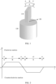
- FIG. 1 is a diagram of an example of reciprocating motion of a reflecting mirror according to an embodiment of this application.
- a reflecting mirror 110 is connected to a motor 120 through a rotating shaft 130, so that the motor 120 can drive, through the rotating shaft 130, the reflecting mirror 110 to perform reciprocating motion.
- the reciprocating motion of the reflecting mirror may be applied to the field of lidars (light detection and ranging, Lidars).
- the reflecting mirror performs the reciprocating motion within a specific field of view (field of view, FOV), so that scanning coverage of a laser beam in space can be implemented.
- FOV field of view
- moving speeds at two ends of the reflecting mirror need to experience a state A to a state F.
- the reflecting mirror performs clockwise motion, the moving speed gradually increases from 0 to a target speed, and acceleration time is t1.
- the reflecting mirror performs clockwise motion, and keeps performing uniform motion at the target speed, and uniform motion time is t2.
- the reflecting mirror performs clockwise motion, the moving speed gradually decreases from the target speed to 0, and deceleration time is t1.
- the reflecting mirror performs counterclockwise motion, the moving speed gradually increases from 0 to the target speed, and acceleration time is t1.
- the reflecting mirror performs counterclockwise motion, and keeps performing uniform motion at the target speed, and uniform motion time is t2.
- the reflecting mirror performs counterclockwise motion, the moving speed gradually decreases from the target speed to 0, and deceleration time is t1. Refer to a diagram of an example of a curve of a moving speed and time of the reflecting mirror shown in FIG. 2 .
- ⁇ is the lighting efficiency
- t1 is time for performing acceleration motion or deceleration motion each time
- t2 is time for performing uniform motion each time.
- completion time of the acceleration motion or the deceleration motion in the reciprocating motion of the laser reflecting mirror should be reduced as much as possible, which imposes a higher requirement on a driving component like a motor.
- this application proposes a driving apparatus of a reflecting mirror.
- a power assisting apparatus is combined to assist in acceleration motion or deceleration motion in the reciprocating motion of the reflecting mirror, so that completion time of the acceleration motion or the deceleration motion in the reciprocating motion of the reflecting mirror can be reduced. In this way, a requirement on the motor is reduced.
- FIG. 3 shows a driving apparatus of a reflecting mirror according to an embodiment of this application.
- a driving apparatus 300 of a reflecting mirror 310 includes a motor 320 and a first power assisting apparatus 330.
- the motor 320 is configured to drive the reflecting mirror 310 to move.
- the motor 320 may be alternatively replaced with another component having a driving function. This is not limited in this application. However, for ease of description, in this application, the motor is used as an example.
- driving the reflecting mirror 310 to move includes driving the reflecting mirror 310 to perform reciprocating motion.
- the reflecting mirror 310 performing the reciprocating motion may also be referred to as an oscillating mirror. This is not limited in this application. It should be understood that, in a process of performing the reciprocating motion, uniform motion, acceleration motion, and deceleration motion are involved.
- a first end 331 of the first power assisting apparatus 330 is fastened to a first end 311 of the reflecting mirror 310, a second end 332 of the first power assisting apparatus 330 is fastened to a first position 340, the first position 340 is fixed relative to the motor 320, and the first power assisting apparatus 330 acts on the first end 311 of the reflecting mirror 310 for the acceleration motion and/or the deceleration motion.
- the first end 311 of the reflecting mirror 310 is mainly one of two ends that are of the reflecting mirror 310 and that perform the reciprocating motion.
- the reflecting mirror 310 one surface used to reflect a light beam is referred to as a front surface or a reflective surface, and the other surface is referred to as a back surface.
- the first end 331 of the first power assisting apparatus 330 may be fastened to a back surface of the first end 311 of the reflecting mirror 310.
- the first position 340 may be located on a housing of the motor 320, or may be another position fixed relative to the motor 320, provided that the first power assisting apparatus 330 fastened to this position can assist the first end 311 of the reflecting mirror 310 in the acceleration motion and/or the deceleration motion.
- the first power assisting apparatus 330 acts on the first end 311 of the reflecting mirror 310 for the acceleration motion and/or the deceleration motion mainly means that the first power assisting apparatus 330 can assist the first end 311 of the reflecting mirror 310 in performing the acceleration motion and/or the deceleration motion.
- the first power assisting apparatus 330 can assist the first end 311 of the reflecting mirror 310 while the motor 320 drives the first end 311 of the reflecting mirror 310 to perform the acceleration motion and/or the deceleration motion.
- the driving apparatus 300 of the reflecting mirror 310 provided in embodiments of this application further includes the first power assisting apparatus 330, and the first power assisting apparatus 330 can act on the first end 311 of the reflecting mirror 310 for the acceleration motion and/or the deceleration motion, to avoid a case in which the acceleration motion and/or the deceleration motion of the first end 311 of the reflecting mirror 310 are/is driven by only the motor 320. In this way, a requirement on the motor 320 can be reduced.
- the direction of the force applied to the first end 311 of the reflecting mirror 310 by the first power assisting apparatus 330 is opposite to the moving direction of the first end 311 of the reflecting mirror 310, so that the first end 311 of the reflecting mirror 310 can be assisted in performing the deceleration motion.
- the direction of the force applied to the first end 311 of the reflecting mirror 310 by the first power assisting apparatus 330 is the same as the moving direction of the first end 311 of the reflecting mirror 310, so that the first end 311 of the reflecting mirror 310 can be assisted in performing the acceleration motion. In this way, the requirement on the motor 320 can be reduced.
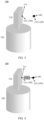
- the first power assisting apparatus 330 may include a first spring, as shown in FIG. 4 .
- the first power assisting apparatus 330 when the first power assisting apparatus 330 includes the first spring, the first end 311 of the reflecting mirror 310 compresses or stretches the first spring during the reciprocating motion, to generate a pushing force or a pulling force on the first end 311 of the reflecting mirror 310, so as to assist the first end 311 of the reflecting mirror 310 in the acceleration motion and/or the deceleration motion.
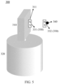
- the first end 331 of the first power assisting apparatus 330 may include a first permanent magnet
- the second end 332 of the first power assisting apparatus 330 may include a second permanent magnet
- An upper side of the first permanent magnet is an N pole, and a lower side is an S pole.
- An upper side of the second permanent magnet is also an N pole, and a lower side is an S pole.
- an upper side of the first permanent magnet is an S pole, and a lower side is an N pole.
- An upper side of the second permanent magnet is also an S pole, and a lower side is an N pole. This is not shown in the figure.
- an acting force generated between the first permanent magnet and the second permanent magnet is a repulsive force
- the repulsive force between the first permanent magnet and the second permanent magnet increases as a distance between the first permanent magnet and the second permanent magnet decreases, and decreases as the distance increases.
- a distance between the first position 340 and the first end 311 of the reflecting mirror 310 may be appropriately controlled to control a magnitude of the repulsive force, so that when the first end 311 of the reflecting mirror 310 performs the acceleration motion or the deceleration motion at a position close to the first position 340, time of the acceleration motion or the deceleration motion is shortened under action of the repulsive force, and when the first end 311 of the reflecting mirror 310 performs the acceleration motion or the deceleration motion at a position far away from the first position 340, the acceleration motion or the deceleration motion is not affected by the first permanent magnet and the second permanent magnet.
- the first end 331 of the first power assisting apparatus 330 may include a third permanent magnet, and the second end 332 of the first power assisting apparatus 330 may include a first electromagnet, as shown in FIG. 6 .
- an upper side of the third permanent magnet may be an N pole, and a lower side may be an S pole, or an upper side of the third permanent magnet may be an S pole, and a lower side may be an N pole.
- the electromagnet may control a direction of a magnetic field by changing a direction of an electrified current. Therefore, the third permanent magnet and the first electromagnet can be controlled to generate an attractive force or a repulsive force.
- the direction of the magnetic field of the electromagnet may be controlled, so that when the first end 311 of the reflecting mirror 310 performs the deceleration motion, the direction of the force applied to the first end 311 of the reflecting mirror 310 by the first power assisting apparatus 330 is opposite to the moving direction of the first end 311 of the reflecting mirror 310, and when the first end 311 of the reflecting mirror 310 performs the acceleration motion, the direction of the force applied to the first end 311 of the reflecting mirror 310 by the first power assisting apparatus 330 is the same as the moving direction of the first end 311 of the reflecting mirror
- the permanent magnet in this application may be a magnet patch attached to the first end 311 of the reflecting mirror 310 or the first position 340, or may be a magnet block embedded in the first end 311 of the reflecting mirror 310 or the first position 340, or may be fastened to the first end 311 of the reflecting mirror 310 or the first position 340 in another form. This is not limited in this application.
- the first power assisting apparatus 330 is merely an example.
- the first end 331 and the second end 332 of the first power assisting apparatus 330 each may include an electromagnet or a permanent magnet. This is not limited in this application.
- disposing an electromagnet at or embedding a magnet block in the first end 311 of the reflecting mirror 310 increases complexity of a manufacturing process of the first end 311 of the reflecting mirror 310. Therefore, in this application, to simplify the manufacturing process of the first end 311 of the reflecting mirror 310, when the first end 331 of the first power assisting apparatus 330 includes a permanent magnet, a magnet patch is selected, and is attached to the first end 311 of the reflecting mirror 310.
- a magnet patch or a magnet block may be selected. This is not limited.
- the apparatus 300 may further include a controller.
- the controller may be configured to control to conduct or interrupt a current passing through the first electromagnet, so that the first power assisting apparatus 330 acts on the first end 311 of the reflecting mirror 310 for the acceleration motion and/or the deceleration motion.
- the first end 311 of the reflecting mirror 310 can be assisted in the acceleration motion and/or the deceleration motion by using only the spring or the permanent magnet, it is easy to interfere with uniform motion of the first end 311 of the reflecting mirror 310 to some extent.
- the current passing through the first electromagnet may be controlled to be conducted or interrupted, so that the first power assisting apparatus 330 acts on the first end 311 of the reflecting mirror 310 for the acceleration motion and/or the deceleration motion. In this way, the requirement on the motor 320 can be reduced. This can further avoid interference caused by only the power assisting apparatus like the permanent magnet or the spring to the uniform motion of the first end 311 of the reflecting mirror 310, and improve drive control performance of the power assisting apparatus in a motion process of the reflecting mirror 310.
- the controller may be further configured to: control to conduct the current passing through the first electromagnet, so that a direction of a force that is generated by the third permanent magnet and the first electromagnet and that is applied to the first end 311 of the reflecting mirror 310 is the same as the moving direction of the first end 311 of the reflecting mirror 310; and/or control to interrupt the current passing through the first electromagnet, so that the first end 311 of the reflecting mirror 310 keeps performing uniform motion under driving of the motor 320; and/or control to conduct the current passing through the first electromagnet, so that the direction of the force that is generated by the third permanent magnet and the first electromagnet and that is applied to the first end 311 of the reflecting mirror 310 is opposite to the moving direction of the first end 311 of the reflecting mirror 310.
- the current passing through the first electromagnet may be controlled to be conducted, so that the direction of the force that is generated by the third permanent magnet and the first electromagnet and that is applied to the first end 311 of the reflecting mirror 310 is the same as the moving direction of the first end 311 of the reflecting mirror 310.
- the current passing through the first electromagnet is controlled to be interrupted, so that the first end 311 of the reflecting mirror 310 keeps performing the uniform motion under driving of the motor 320.
- the current passing through the first electromagnet is controlled to be conducted, so that the direction of the force that is generated by the third permanent magnet and the first electromagnet and that is applied to the first end 311 of the reflecting mirror 310 is opposite to the moving direction of the first end 311 of the reflecting mirror 310.
- the controller may be further configured to periodically control the current passing through the first electromagnet to be conducted or interrupted, so that the first power assisting apparatus periodically acts on the first end 311 of the reflecting mirror 310 for the acceleration motion and/or the deceleration motion.
- the current passing through the first electromagnet may be periodically controlled to be conducted or interrupted, so that the first power assisting apparatus 330 periodically acts on the first end 311 of the reflecting mirror 310 for the acceleration motion and/or the deceleration motion.
- the requirement on the motor 320 can be reduced. This can further avoid interference caused by the power assisting apparatus like the permanent magnet or the spring to the uniform motion of the first end 311 of the reflecting mirror 310, and improve drive control performance of the power assisting apparatus in reciprocating motion process of the reflecting mirror 310.
- the apparatus 300 may further include a second power assisting apparatus 350, as shown in FIG. 7 .
- a first end 351 of the second power assisting apparatus 350 is fastened to a second end 312 of the reflecting mirror 310, a second end 352 of the second power assisting apparatus 350 is fastened to a second position 360, the second position 360 is fixed relative to the motor 320, and the second power assisting apparatus 350 acts on the second end 312 of the reflecting mirror 310 for acceleration motion and/or deceleration motion.
- the second end 312 of the reflecting mirror 310 is mainly the other one of the two ends that are of the reflecting mirror 310 and that perform the reciprocating motion.
- the first end 351 of the second power assisting apparatus 350 may be fastened to a back surface of the second end 312 of the reflecting mirror 310.
- the first end 331 of the first power assisting apparatus 330 and the first end 351 of the second power assisting apparatus 350 may be fastened to a same surface of the reflecting mirror 310, for example, are fastened to the front surface or the back surface of the reflecting mirror 310, or may be fastened to different surfaces, for example, one is fastened to the front surface and the other is fastened to the back surface.
- both the first end 331 of the first power assisting apparatus 330 and the first end 351 of the second power assisting apparatus 350 are fastened to the back surface of the reflecting mirror 310.
- the second position 360 may be located on the housing of the motor 320, or may be another position fixed relative to the motor 320, provided that the second power assisting apparatus fastened to this position can assist the second end 312 of the reflecting mirror 310 in performing the acceleration motion and/or the deceleration motion.
- the second power assisting apparatus 350 acts on the second end 312 of the reflecting mirror 310 for the acceleration motion and/or the deceleration motion mainly means that the second power assisting apparatus 350 can assist the second end 312 of the reflecting mirror 310 in performing the acceleration motion and/or the deceleration motion.
- the second power assisting apparatus 350 can assist the second end 312 of the reflecting mirror 310 while the motor 320 drives the second end 312 of the reflecting mirror 310 to perform the acceleration motion and/or the deceleration motion.
- the driving apparatus 300 of the reflecting mirror 310 may further include the second power assisting apparatus 350, and the second power assisting apparatus 350 can act on the second end 312 of the reflecting mirror 310 for the acceleration motion and/or the deceleration motion, to avoid a case in which the acceleration motion and/or the deceleration motion of the second end 312 of the reflecting mirror 310 are/is driven by only the motor 320. In this way, the requirement on the motor 320 can be reduced.
- the direction of the force applied to the second end 312 of the reflecting mirror 310 by the second power assisting apparatus 350 is opposite to the moving direction of the second end 312 of the reflecting mirror 310, so that the second end 312 of the reflecting mirror 310 can be assisted in performing the deceleration motion.
- the direction of the force applied to the second end 312 of the reflecting mirror 310 by the second power assisting apparatus 350 is the same as the moving direction of the second end 312 of the reflecting mirror 310, so that the second end 312 of the reflecting mirror 310 can be assisted in performing the acceleration motion. In this way, the requirement on the motor 320 can be reduced.
- the second power assisting apparatus 350 includes a second spring, as shown in FIG. 8 .
- the second power assisting apparatus 350 includes the second spring
- the second end 312 of the reflecting mirror 310 compresses or stretches the second spring during the reciprocating motion, to generate a pushing force or a pulling force on the second end 312 of the reflecting mirror 310, so as to assist the second end 312 of the reflecting mirror 310 in the acceleration motion and/or the deceleration motion.
- the first end 351 of the second power assisting apparatus 350 may include a fourth permanent magnet, and the second end 352 of the second power assisting apparatus 350 may include a fifth permanent magnet.
- An upper side of the fourth permanent magnet is an N pole, and a lower side is an S pole.
- An upper side of the fifth permanent magnet is also an N pole, and a lower side is an S pole.
- an upper side of the fourth permanent magnet is an S pole, and a lower side is an N pole.
- An upper side of the fifth permanent magnet is also an S pole, and a lower side is an N pole. This is not shown in the figure.
- an acting force generated between the fourth permanent magnet and the fifth permanent magnet is a repulsive force
- the repulsive force between the fourth permanent magnet and the fifth permanent magnet increases as a distance between the fourth permanent magnet and the fifth permanent magnet decreases, and decreases as the distance increases.
- a distance between the second position 360 and the second end 312 of the reflecting mirror 310 may be appropriately controlled to control a magnitude of the repulsive force, so that when the second end 312 of the reflecting mirror 310 performs the acceleration motion or the deceleration motion at a position close to the second position 360, time of the acceleration motion or the deceleration motion is shortened under action of the repulsive force, and when the second end 312 of the reflecting mirror 310 performs the acceleration motion or the deceleration motion at a position far away from the second position 360, the acceleration motion or the deceleration motion is not affected by the fourth permanent magnet and the fifth permanent magnet.
- the first end 351 of the second power assisting apparatus 350 includes a sixth permanent magnet
- the second end 352 of the second power assisting apparatus 350 includes a second electromagnet, as shown in FIG. 10 .
- an upper side of the sixth permanent magnet may be an N pole, and a lower side may be an S pole, or an upper side of the sixth permanent magnet may be an S pole, and a lower side may be an N pole.
- the electromagnet may control a direction of a magnetic field by changing a direction of an electrified current. Therefore, the sixth permanent magnet and the second electromagnet can be controlled to generate an attractive force or a repulsive force.
- the direction of the magnetic field of the electromagnet may be controlled, so that when the second end 312 of the reflecting mirror 310 performs the deceleration motion, the direction of the force applied to the second end 312 of the reflecting mirror 310 by the second power assisting apparatus 350 is opposite to the moving direction of the second end 312 of the reflecting mirror 310, and when the second end 312 of the reflecting mirror 310 performs the acceleration motion, the direction of the force applied to the second end 312 of the reflecting mirror 310 by the second power assisting apparatus 350 is the same as the moving direction of the second end 312 of the reflecting mirror 310.
- the permanent magnet in this application may be a magnet patch attached to the second end 312 of the reflecting mirror 310 or the second position 360, or may be a magnet block embedded in the second end 312 of the reflecting mirror 310 or the second position 360, or may be fastened to the second end 312 of the reflecting mirror 310 or the second position 360 in another form. This is not limited in this application.
- the second power assisting apparatus 350 is merely an example.
- the first end 351 and the second end 352 of the second power assisting apparatus 350 each may include an electromagnet or a permanent magnet. This is not limited in this application.
- disposing an electromagnet at or embedding a magnet block in the second end 312 of the reflecting mirror 310 increases complexity of a manufacturing process of the second end 312 of the reflecting mirror 310. Therefore, in this application, to simplify the manufacturing process of the second end 312 of the reflecting mirror 310, when the first end 351 of the second power assisting apparatus 350 includes a permanent magnet, a magnet patch is selected, and is attached to the second end 312 of the reflecting mirror 310.
- a magnet patch or a magnet block may be selected. This is not limited.
- the first power assisting apparatus 330 and the second power assisting apparatus 350 may be the same or different.
- the first power assisting apparatus 330 and the second power assisting apparatus 350 each may include a spring.
- the first power assisting apparatus 330 includes a spring
- the first end 351 and the second end 352 of the second power assisting apparatus 350 each include a permanent magnet.
- the first end 331 and the second end 332 of the first power assisting apparatus 330 respectively include a permanent magnet and an electromagnet
- the first end 351 and the second end 352 of the second power assisting apparatus 350 each include a permanent magnet. This is not limited in this application.
- the controller may be further configured to control a current passing through the second electromagnet to be conducted or interrupted, so that the second power assisting apparatus 350 acts on the second end 312 of the reflecting mirror 310 for the acceleration motion and/or the deceleration motion.
- the current passing through the second electromagnet may be controlled to be conducted or interrupted, so that the second power assisting apparatus 350 acts on the second end 312 of the reflecting mirror 310 for the acceleration motion and/or the deceleration motion.
- the requirement on the motor 320 can be reduced. This can further avoid interference caused by the power assisting apparatus like the permanent magnet or the spring to the uniform motion of the second end 312 of the reflecting mirror 310, and improve drive control performance of the power assisting apparatus in a motion process of the reflecting mirror 310.
- the controller may be further configured to: control to conduct the current passing through the second electromagnet, so that a direction of a force that is generated by the sixth permanent magnet and the second electromagnet and that is applied to the second end 312 of the reflecting mirror 310 is the same as the moving direction of the second end 312 of the reflecting mirror 310; and/or control to interrupt the current passing through the second electromagnet, so that the second end 312 of the reflecting mirror 310 keeps performing uniform motion under driving of the motor 320; and/or control to conduct the current passing through the second electromagnet, so that the direction of the force that is generated by the sixth permanent magnet and the second electromagnet and that is applied to the second end 312 of the reflecting mirror 310 is opposite to the moving direction of the second end 312 of the reflecting mirror 310.
- the current passing through the second electromagnet may be controlled to be conducted, so that the direction of the force that is generated by the sixth permanent magnet and the second electromagnet and that is applied to the second end 312 of the reflecting mirror 310 is the same as the moving direction of the second end 312 of the reflecting mirror 310.
- the current passing through the second electromagnet is controlled to be interrupted, so that the second end 312 of the reflecting mirror 310 keeps performing the uniform motion under driving of the motor 320.
- the current passing through the second electromagnet is controlled to be conducted, so that the direction of the force that is generated by the sixth permanent magnet and the second electromagnet and that is applied to the second end 312 of the reflecting mirror 310 is opposite to the moving direction of the second end 312 of the reflecting mirror 310.
- the controller may be further configured to periodically control the current passing through the second electromagnet to be conducted or interrupted, so that the second power assisting apparatus 350 periodically acts on the second end 312 of the reflecting mirror 310 for the acceleration motion and/or the deceleration motion.
- the current passing through the second electromagnet may be periodically controlled to be conducted or interrupted, so that the second power assisting apparatus 350 periodically acts on the second end 312 of the reflecting mirror 310 for the acceleration motion and/or the deceleration motion.
- the requirement on the motor 320 can be reduced. This can further avoid interference caused by the power assisting apparatus like the permanent magnet or the spring to the uniform motion of the second end 312 of the reflecting mirror 310, and improve drive control performance of the power assisting apparatus in reciprocating motion process of the reflecting mirror 310.
- Embodiment 1 The following describes an optional solution and an assisting process of the driving apparatus by using examples with reference to Embodiment 1 and Embodiment 2.
- FIG. 11 is a diagram of an example of a driving apparatus 1100 according to an embodiment of this application.
- the first end 331 and the second end 332 of the first power assisting apparatus 330 and the first end 351 and the second end 352 of the second power assisting apparatus 350 each include the permanent magnet, and both the first position 340 and the second position 360 are located on the housing 370 of the motor 320.
- the first end 331 of the first power assisting apparatus 330 and the first end 351 of the second power assisting apparatus 350 each include the magnet patch, and the magnet patches are attached to the back surfaces of the first end 311 and the second end 312 of the reflecting mirror 310.
- the permanent magnet shown in FIG. 11 is merely an example.
- an upper side of each permanent magnet may be an S pole, and a lower side is an N pole, or an upper side of the permanent magnet corresponding to the first power assisting apparatus 330 is an S pole and a lower side is an N pole, and an upper side of the permanent magnet corresponding to the second power assisting apparatus 350 is an N pole, and a lower side is an S pole.
- an assisting process is as follows.
- a repulsive force is applied, during the deceleration motion, to one end that is of the two ends and that is close to the housing 370.
- the moving direction is opposite to a direction of the repulsive force. This helps the end complete the deceleration motion.
- the repulsive force is still applied to the end. In this case, the moving direction is consistent with the direction of the repulsive force. This helps the end complete the acceleration motion, until the reflecting mirror starts to perform the uniform motion.
- the permanent magnet provides an acting force between the reflecting mirror 310 and the housing 370, to help the motor 320 control the acceleration motion or the deceleration motion of the reflecting mirror, a drive current required by the motor 320 to control motion of the oscillating mirror is smaller.
- a control capability for the acceleration motion or the deceleration motion of the reflecting mirror 310 can be improved, and a requirement of the reflecting mirror on a driving component and a control algorithm is reduced.
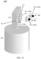
- FIG. 12 is a diagram of an example of a driving apparatus 1200 according to an embodiment of this application.
- the first end 331 of the first power assisting apparatus 330 includes the permanent magnet
- the second end 332 includes the electromagnet
- the first end 351 of the second power assisting apparatus 350 includes the permanent magnet
- the second end 352 includes the electromagnet.
- the first end 331 of the first power assisting apparatus 330 and the first end 351 of the second power assisting apparatus 350 each include the magnet patch, and the magnet patches are attached to the back surfaces of the first end 311 and the second end 312 of the reflecting mirror 310.
- the permanent magnet shown in FIG. 12 is merely an example.
- an upper side of the permanent magnet may be an S pole, and a lower side is an N pole, or an upper side of the permanent magnet corresponding to the first power assisting apparatus 330 is an S pole and a lower side is an N pole, and an upper side of the permanent magnet corresponding to the second power assisting apparatus 350 is an N pole, and a lower side is an S pole. This is not limited in this application.
- the upper side of the permanent magnet is the N pole, and the lower side is the S pole is used for description.
- the direction of the magnetic field of the electromagnet may be controlled by using a direction of a coil current, to control the acting force between the electromagnet and the permanent magnet to be an attractive force or a repulsive force.
- electromagnet A the electromagnet corresponding to the second end 332 of the first power assisting apparatus 330
- electromagnet B the electromagnet corresponding to the second end 352 of the second power assisting apparatus 350
- an assisting process is as follows.
- the reflecting mirror 310 When the reflecting mirror 310 performs clockwise acceleration motion (that is, in the state A), the first end 311 of the reflecting mirror 310 is far away from the electromagnet A, and the second end 312 of the reflecting mirror 310 is close to the electromagnet B.
- the electromagnet A is controlled to be powered on, so that the upper side is the S pole and the lower side is the N pole, to generate an attractive force on the first end 311 of the reflecting mirror 310
- the electromagnet B is controlled to be powered on, so that the upper side is the N pole and the lower side is the S pole, to generate a repulsive force on the second end 312 of the reflecting mirror 310, to assist the reflecting mirror 310 in performing the clockwise acceleration motion.
- the electromagnet A and the electromagnet B are controlled to be powered off. In this way, the uniform motion of the reflecting mirror 310 is not affected.
- the reflecting mirror When the reflecting mirror performs clockwise deceleration motion (that is, in the state C), the first end 311 of the reflecting mirror 310 is close to the electromagnet A, and the second end 312 of the reflecting mirror 310 is far away from the electromagnet B.
- the electromagnet A is controlled to be powered on, so that the upper side is the N pole and the lower side is the S pole, to generate a repulsive force on the first end 311 of the reflecting mirror 310
- the electromagnet B is controlled to be powered on, so that the upper side is the S pole and the lower side is the N pole, to generate an attractive force on the second end 312 of the reflecting mirror 310, to assist the reflecting mirror 310 in performing the clockwise deceleration motion, until the speed of the reflecting mirror decreases to 0 and the reflecting mirror performs reverse motion.
- the electromagnet may be used to control effect of the magnetic field by conducting and interrupting the current passing through the electromagnet.
- the current passing through the electromagnet is interrupted, and the reflecting mirror 310 performs motion control through driving of the motor 320.
- the reflecting mirror 310 moves to an acceleration stage or a deceleration stage, the current passing through the electromagnet is conducted, and a magnetic field acting force is generated between the reflecting mirror 310 and the electromagnet, to assist the reflecting mirror 310 in the acceleration motion or the deceleration motion.
- this embodiment can avoid interference caused by only the permanent magnet to the uniform motion of the reflecting mirror 310, and can improve drive control performance of the power assisting apparatus in a full motion stage of the reflecting mirror 310.
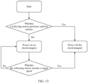
- FIG. 13 is a diagram of an example of control logic of an electromagnet according to an embodiment of this application.
- the control logic of the electromagnet is as follows: first, determining whether a reflecting mirror performs uniform motion, and when the reflecting mirror performs the uniform motion, controlling the electromagnet to be powered off; or when the reflecting mirror performs non-uniform motion, powering on the electromagnet, where a direction of an electrified current is mainly determined by a moving direction and a speed of the reflecting mirror, to help the reflecting mirror perform acceleration motion or deceleration motion.
- a direction of an electrified current is mainly determined by a moving direction and a speed of the reflecting mirror, to help the reflecting mirror perform acceleration motion or deceleration motion.
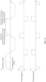
- powering on and powering off of the electromagnet may be controlled based on a time sequence of the uniform motion, the acceleration motion, and the deceleration motion.
- the following describes time sequence control of the electromagnet with reference to FIG. 14 .
- FIG. 14 is a diagram of an example of time sequence control of an electromagnet according to an embodiment of this application.
- a reflecting mirror performs uniform motion
- two electromagnets are powered off.
- the two electromagnets are separately powered on to generate magnetic forces, and directions of magnetic fields are opposite, so that the force applied to one end that is of the reflecting mirror and that is close to the electromagnet is a repulsive force and the force applied to one end that is of the reflecting mirror and that is away from the electromagnet is an attractive force, and the reflecting mirror is pushed to complete an acceleration motion stage and a deceleration motion stage.
- FIG. 15 is a diagram of an example of a driving method of a reflecting mirror according to an embodiment of this application. It should be understood that the method 1500 is applied to a driving apparatus including a motor and a first power assisting apparatus.
- the motor is configured to drive the reflecting mirror to move.
- a first end of the first power assisting apparatus includes a third permanent magnet
- a second end of the first power assisting apparatus includes a first electromagnet
- the third permanent magnet is fastened to a first end of the reflecting mirror
- the first electromagnet is fastened to a first position
- the first position is fixed relative to the motor.
- the method 1500 includes step S1510: controlling to conduct or interrupt a current passing through the first electromagnet.
- a purpose of controlling to conduct or interrupt the current passing through the first electromagnet is to enable the first power assisting apparatus to act on the first end of the reflecting mirror for acceleration motion and/or deceleration motion.
- the driving method of the reflecting mirror may be applied to the driving apparatus including the motor and the first power assisting apparatus.
- the motor is configured to drive the reflecting mirror to move.
- the first end of the first power assisting apparatus includes the third permanent magnet
- the second end of the first power assisting apparatus includes the first electromagnet
- the third permanent magnet is fastened to the first end of the reflecting mirror
- the first electromagnet is fastened to the first position
- the first position is fixed relative to the motor.
- the current passing through the first electromagnet may be controlled to be conducted or interrupted, so that the first power assisting apparatus acts on the first end of the reflecting mirror for the acceleration motion and/or the deceleration motion. In this way, a requirement on the motor can be reduced. This can further avoid interference caused by the power assisting apparatus like the permanent magnet or a spring to uniform motion of the first end of the reflecting mirror, and improve drive control performance of the power assisting apparatus in a motion process of the reflecting mirror.
- controlling to conduct or interrupt a current passing through the first electromagnet may include: controlling to conduct the current passing through the first electromagnet, so that a direction of a force that is generated by the third permanent magnet and the first electromagnet and that is applied to the first end of the reflecting mirror is the same as a moving direction of the first end of the reflecting mirror; and/or controlling to interrupt the current passing through the first electromagnet, so that the first end of the reflecting mirror keeps performing uniform motion under driving of the motor; and/or controlling to conduct the current passing through the first electromagnet, so that the direction of the force that is generated by the third permanent magnet and the first electromagnet and that is applied to the first end of the reflecting mirror is opposite to the moving direction of the first end of the reflecting mirror.
- controlling to conduct or interrupt a current passing through the first electromagnet may further include: periodically controlling to conduct or interrupt the current passing through the first electromagnet.
- a purpose of periodically controlling to conduct or interrupt the current passing through the first electromagnet is to enable the first power assisting apparatus to periodically act on the first end of the reflecting mirror for the acceleration motion and/or the deceleration motion.
- the driving apparatus may further include a second power assisting apparatus.
- a first end of the second power assisting apparatus includes a sixth permanent magnet
- a second end of the second power assisting apparatus includes a second electromagnet
- the sixth permanent magnet is fastened to a second end of the reflecting mirror
- the second electromagnet is fastened to a second position
- the second position is fixed relative to the motor.
- the method 1500 may further include step S 1520: controlling to conduct or interrupt a current passing through the second electromagnet.
- a purpose of controlling to conduct or interrupt the current passing through the second electromagnet is to enable the second power assisting apparatus to act on the second end of the reflecting mirror for the acceleration motion and/or the deceleration motion.
- steps S1510 and S 1520 may be performed simultaneously. This is not limited in this application.
- the driving apparatus may further include the second power assisting apparatus.
- the first end of the second power assisting apparatus includes the sixth permanent magnet
- the second end of the second power assisting apparatus includes the second electromagnet
- the sixth permanent magnet is fastened to the second end of the reflecting mirror
- the second electromagnet is fastened to the second position
- the second position is fixed relative to the motor.
- the current passing through the second electromagnet may be controlled to be conducted or interrupted, so that the second power assisting apparatus acts on the second end of the reflecting mirror for the acceleration motion and/or the deceleration motion. In this way, the requirement on the motor can be reduced. This can further avoid interference caused by the power assisting apparatus like the permanent magnet or a spring to uniform motion of the second end of the reflecting mirror, and improve drive control performance of the power assisting apparatus in a motion process of the reflecting mirror.
- controlling to conduct or interrupt a current passing through the second electromagnet may include: controlling to conduct the current passing through the second electromagnet, so that a direction of a force that is generated by the sixth permanent magnet and the second electromagnet and that is applied to the second end of the reflecting mirror is the same as a moving direction of the second end of the reflecting mirror; and/or controlling to interrupt the current passing through the second electromagnet, so that the second end of the reflecting mirror keeps performing uniform motion under driving of the motor; and/or controlling to conduct the current passing through the second electromagnet, so that the direction of the force that is generated by the sixth permanent magnet and the second electromagnet and that is applied to the second end of the reflecting mirror is opposite to the moving direction of the second end of the reflecting mirror.
- controlling to conduct or interrupt a current passing through the second electromagnet may further include: periodically controlling to conduct or interrupt the current passing through the second electromagnet.
- a purpose of periodically controlling to conduct or interrupt the current passing through the second electromagnet is to enable the second power assisting apparatus to periodically act on the second end of the reflecting mirror for the acceleration motion and/or the deceleration motion.
- FIG. 16 is a block diagram of an example of a hardware structure of a driving apparatus of a reflecting mirror according to an embodiment of this application.
- an apparatus 1600 may be specifically a computer device.
- the apparatus 1600 includes a memory 1610, a processor 1620, a communication interface 1630, and a bus 1640.
- the memory 1610, the processor 1620, and the communication interface 1630 implement communication connection between each other through the bus 1640.
- the memory 1610 may be a read-only memory (read-only memory, ROM), a static storage device, a dynamic storage device, or a random access memory (random access memory, RAM).
- the memory 1610 may store a program. When the program stored in the memory 1610 is executed by the processor 1620, the processor 1620 is configured to perform the steps of the driving method in embodiments of this application.
- the processor 1620 may be a general-purpose CPU, a microprocessor, an ASIC, a graphics processing unit (graphics processing unit, GPU), or one or more integrated circuits, and is configured to execute a related program, to implement the driving method in the method embodiment of this application.
- the processor 1620 may alternatively be an integrated circuit chip, and has a signal processing capability.
- the driving method in this application may be implemented through an integrated logic circuit of hardware in the processor 1620 or instructions in a form of software.
- the processor 1620 may alternatively be a general-purpose processor, a digital signal processor (digital signal processor, DSP), an ASIC, an FPGA or another programmable logic device, a discrete gate or a transistor logic device, or a discrete hardware component.
- DSP digital signal processor
- ASIC application specific integrated circuit
- FPGA field-programmable gate array
- FPGA field-programmable gate array
- the methods, the steps, and logical block diagrams that are disclosed in embodiments of this application may be implemented or performed.
- the general-purpose processor may be a microprocessor, or the processor may be any conventional processor or the like.
- the steps of the methods disclosed with reference to embodiments of this application may be directly executed and accomplished by a hardware decoding processor, or may be executed and accomplished by using a combination of hardware and software modules in the decoding processor.
- a software module may be located in a mature storage medium in the art, for example, a random access memory, a flash memory, a read-only memory, a programmable read-only memory, an electrically erasable programmable memory, or a register.
- the storage medium is located in the memory 1610.
- the processor 1620 reads information in the memory 1610, and completes, in combination with hardware of the processor 1620, functions that need to be performed by modules included in the apparatus in embodiments of this application, or performs the driving method in the method embodiment of this application.
- the communication interface 1630 uses a transceiver apparatus, for example, but not limited to, a transceiver, to implement communication between the apparatus 1600 and another device or a communication network.
- a transceiver apparatus for example, but not limited to, a transceiver, to implement communication between the apparatus 1600 and another device or a communication network.
- the bus 1640 may include a channel on which information is transmitted between the components (for example, the memory 1610, the processor 1620, and the communication interface 1630) of the apparatus 1600.
- An embodiment of this application further provides a radar, including the driving apparatus 300, the driving apparatus 1100, or the driving apparatus 1200 in embodiments of this application.
- An embodiment of this application further provides a terminal, including the driving apparatus 300, the driving apparatus 1100, or the driving apparatus 1200 in embodiments of this application.
- the terminal may be an intelligent transportation device (a vehicle or an uncrewed aerial vehicle), a smart home device, an intelligent manufacturing device, a surveying and mapping device, a robot, or the like.
- the intelligent transportation device may be, for example, an automated guided vehicle (automated guided vehicle, AGV) or an uncrewed transportation vehicle.
- An embodiment of this application further provides a computer-readable storage medium, including instructions.
- the instructions are used to implement the method 1500.
- An embodiment of this application further provides a computer program product, including a computer program.
- the computer program When the computer program is run, the computer is enabled to perform the method 1500.
- An embodiment of this application further provides a computing device, including at least one processor and a memory.
- the at least one processor is coupled to the memory, and is configured to read and execute instructions in the memory, to perform the method 1500.
- An embodiment of this application further provides a chip, and the chip includes a processor and a data interface.
- the processor reads, through the data interface, instructions stored in a memory, to perform the method 1500.
Landscapes
- Physics & Mathematics (AREA)
- General Physics & Mathematics (AREA)
- Engineering & Computer Science (AREA)
- Optics & Photonics (AREA)
- Computer Networks & Wireless Communication (AREA)
- Radar, Positioning & Navigation (AREA)
- Remote Sensing (AREA)
- Rear-View Mirror Devices That Are Mounted On The Exterior Of The Vehicle (AREA)
- Non-Portable Lighting Devices Or Systems Thereof (AREA)
- Connection Of Motors, Electrical Generators, Mechanical Devices, And The Like (AREA)
Applications Claiming Priority (1)
| Application Number | Priority Date | Filing Date | Title |
|---|---|---|---|
| PCT/CN2022/070794 WO2023130371A1 (zh) | 2022-01-07 | 2022-01-07 | 反射镜的驱动装置、驱动方法、雷达和终端 |
Publications (2)
| Publication Number | Publication Date |
|---|---|
| EP4451004A1 true EP4451004A1 (de) | 2024-10-23 |
| EP4451004A4 EP4451004A4 (de) | 2025-01-08 |
Family
ID=87072825
Family Applications (1)
| Application Number | Title | Priority Date | Filing Date |
|---|---|---|---|
| EP22917843.9A Pending EP4451004A4 (de) | 2022-01-07 | 2022-01-07 | Ansteuerungsvorrichtung für einen reflektierenden spiegel, ansteuerungsverfahren, radar und endgerät |
Country Status (3)
| Country | Link |
|---|---|
| EP (1) | EP4451004A4 (de) |
| CN (1) | CN116724547A (de) |
| WO (1) | WO2023130371A1 (de) |
Family Cites Families (9)
| Publication number | Priority date | Publication date | Assignee | Title |
|---|---|---|---|---|
| JP3127184B2 (ja) * | 1993-09-22 | 2001-01-22 | 三菱電機株式会社 | 車両用レーダ装置 |
| JP2000203118A (ja) * | 1999-01-19 | 2000-07-25 | Canon Inc | 走査装置およびプリント装置 |
| JP2004074166A (ja) * | 2002-08-09 | 2004-03-11 | Hitachi Via Mechanics Ltd | 光学スキャナおよびレーザ加工装置 |
| JP4088188B2 (ja) * | 2003-04-07 | 2008-05-21 | セイコーエプソン株式会社 | プロジェクタ |
| JP2009202556A (ja) * | 2008-02-29 | 2009-09-10 | Brother Ind Ltd | 画像形成装置 |
| JP2011013346A (ja) * | 2009-06-30 | 2011-01-20 | Olympus Corp | 光学機構 |
| CN110133618B (zh) * | 2019-04-19 | 2021-08-17 | 深圳市速腾聚创科技有限公司 | 激光雷达及探测方法 |
| CN110780279A (zh) * | 2019-10-30 | 2020-02-11 | 上海禾赛光电科技有限公司 | 扫描镜组件和包括其的激光雷达 |
| CN213544814U (zh) * | 2020-10-29 | 2021-06-25 | 深圳市镭神智能系统有限公司 | 一种振镜驱动装置及振镜组件 |
-
2022
- 2022-01-07 EP EP22917843.9A patent/EP4451004A4/de active Pending
- 2022-01-07 CN CN202280006002.4A patent/CN116724547A/zh active Pending
- 2022-01-07 WO PCT/CN2022/070794 patent/WO2023130371A1/zh not_active Ceased
Also Published As
| Publication number | Publication date |
|---|---|
| WO2023130371A1 (zh) | 2023-07-13 |
| CN116724547A (zh) | 2023-09-08 |
| EP4451004A4 (de) | 2025-01-08 |
Similar Documents
| Publication | Publication Date | Title |
|---|---|---|
| US10750919B2 (en) | Cleaning machine and path control method therefor | |
| EP4296133A1 (de) | Intelligentes antriebsverfahren und vorrichtung sowie speichermedium und computerprogramm | |
| US8339710B2 (en) | Head up display device | |
| US20240288551A1 (en) | Scanning apparatus for lidar, method for controlling the same, and lidar | |
| WO2019062708A1 (zh) | 无缝切换导航方法、系统、车机及云端服务器 | |
| EP3675534A1 (de) | Kehrmaschine, server, kehrmaschinensteuerungsverfahren und kehrmaschinensteuerungssystem | |
| EP4451004A1 (de) | Ansteuerungsvorrichtung für einen reflektierenden spiegel, ansteuerungsverfahren, radar und endgerät | |
| CN216013778U (zh) | 光学元件驱动机构及光学系统 | |
| CN117060809B (zh) | 一种电机驱动控制方法、装置、存储介质及电机系统 | |
| US20190050188A1 (en) | Electronic device for changing clock | |
| CN115782696B (zh) | 电池加热的控制方法、装置、系统及车辆 | |
| JP2025537007A (ja) | モバイルロボット | |
| EP4606662A1 (de) | Bremssteuerverfahren für autonome betriebsvorrichtung, autonome betriebsvorrichtung und speichermedium | |
| CN115685220A (zh) | 目标探测方法、opa激光雷达及计算机可读存储介质 | |
| CN112078327B (zh) | 混合动力汽车的散热控制方法、装置及存储介质 | |
| JP2021185368A (ja) | 走査方法の決定方法、および計測方法 | |
| CN116338624A (zh) | 一种扫描方法、装置计算机存储介质 | |
| RU94087U1 (ru) | Система управления вентильным электродвигателем вращения антенны рлс | |
| CN110758165A (zh) | 一种充电堆输出控制电路 | |
| KR101875642B1 (ko) | 차량용 모터 제어 장치 및 방법 | |
| CN216209896U (zh) | 用于激光雷达的扫描装置、激光雷达 | |
| US20250201874A1 (en) | Apparatus and method for controlling water emission of a vehicle | |
| JPH06170770A (ja) | マイクロロボット | |
| CN110165861A (zh) | 脉冲激励线性谐振传动器 | |
| KR101322647B1 (ko) | 실시간 모션제어 궤적발생을 위한 모션제어 SoC 및 그 제어방법 |
Legal Events
| Date | Code | Title | Description |
|---|---|---|---|
| STAA | Information on the status of an ep patent application or granted ep patent |
Free format text: STATUS: THE INTERNATIONAL PUBLICATION HAS BEEN MADE |
|
| PUAI | Public reference made under article 153(3) epc to a published international application that has entered the european phase |
Free format text: ORIGINAL CODE: 0009012 |
|
| STAA | Information on the status of an ep patent application or granted ep patent |
Free format text: STATUS: REQUEST FOR EXAMINATION WAS MADE |
|
| 17P | Request for examination filed |
Effective date: 20240716 |
|
| AK | Designated contracting states |
Kind code of ref document: A1 Designated state(s): AL AT BE BG CH CY CZ DE DK EE ES FI FR GB GR HR HU IE IS IT LI LT LU LV MC MK MT NL NO PL PT RO RS SE SI SK SM TR |
|
| RAP1 | Party data changed (applicant data changed or rights of an application transferred) |
Owner name: SHENZHEN YINWANG INTELLIGENTTECHNOLOGIES CO., LTD. |
|
| A4 | Supplementary search report drawn up and despatched |
Effective date: 20241206 |
|
| RIC1 | Information provided on ipc code assigned before grant |
Ipc: G02B 26/10 20060101ALI20241202BHEP Ipc: H04N 3/08 20060101ALI20241202BHEP Ipc: G01S 7/481 20060101AFI20241202BHEP |
|
| DAV | Request for validation of the european patent (deleted) | ||
| DAX | Request for extension of the european patent (deleted) | ||
| STAA | Information on the status of an ep patent application or granted ep patent |
Free format text: STATUS: EXAMINATION IS IN PROGRESS |
|
| 17Q | First examination report despatched |
Effective date: 20251204 |