EP4450701A1 - Zerstäubungsvorrichtung und kleidungsbehandlungsvorrichtung - Google Patents
Zerstäubungsvorrichtung und kleidungsbehandlungsvorrichtung Download PDFInfo
- Publication number
- EP4450701A1 EP4450701A1 EP22905849.0A EP22905849A EP4450701A1 EP 4450701 A1 EP4450701 A1 EP 4450701A1 EP 22905849 A EP22905849 A EP 22905849A EP 4450701 A1 EP4450701 A1 EP 4450701A1
- Authority
- EP
- European Patent Office
- Prior art keywords
- snap
- fit
- box
- box body
- cover
- Prior art date
- Legal status (The legal status is an assumption and is not a legal conclusion. Google has not performed a legal analysis and makes no representation as to the accuracy of the status listed.)
- Pending
Links
Images

Classifications
-
- D—TEXTILES; PAPER
- D06—TREATMENT OF TEXTILES OR THE LIKE; LAUNDERING; FLEXIBLE MATERIALS NOT OTHERWISE PROVIDED FOR
- D06F—LAUNDERING, DRYING, IRONING, PRESSING OR FOLDING TEXTILE ARTICLES
- D06F39/00—Details of washing machines not specific to a single type of machines covered by groups D06F9/00 - D06F27/00
- D06F39/08—Liquid supply or discharge arrangements
- D06F39/088—Liquid supply arrangements
-
- D—TEXTILES; PAPER
- D06—TREATMENT OF TEXTILES OR THE LIKE; LAUNDERING; FLEXIBLE MATERIALS NOT OTHERWISE PROVIDED FOR
- D06F—LAUNDERING, DRYING, IRONING, PRESSING OR FOLDING TEXTILE ARTICLES
- D06F58/00—Domestic laundry dryers
- D06F58/20—General details of domestic laundry dryers
- D06F58/203—Laundry conditioning arrangements
-
- D—TEXTILES; PAPER
- D06—TREATMENT OF TEXTILES OR THE LIKE; LAUNDERING; FLEXIBLE MATERIALS NOT OTHERWISE PROVIDED FOR
- D06F—LAUNDERING, DRYING, IRONING, PRESSING OR FOLDING TEXTILE ARTICLES
- D06F39/00—Details of washing machines not specific to a single type of machines covered by groups D06F9/00 - D06F27/00
- D06F39/12—Casings; Tubs
- D06F39/14—Doors or covers; Securing means therefor
Definitions
- the present disclosure relates to the technical field of atomization, and specifically provides an atomization device and a clothing treatment apparatus.
- An atomization device is a device capable of providing an atomized gas (a large area of small-particle droplets), and it is widely used in clothing treatment apparatuses or humidification apparatuses, etc.
- the atomization devices mostly adopt a structure in which a water passage and an atomization sheet are combined, without an independent water containing chamber.
- the atomization device takes up a lot of space.
- the atomization device needs to be fused with a water inflow system to use water inflow of the water inflow system to achieve water supply to an atomizer; then, under the action of the atomizer, the water is transformed into atomized droplets of small particles, which enter a clothing treatment cylinder to achieve atomization washing of clothing.
- the present disclosure aims to solve the above technical problems, that is, to solve the problems of limited application scenes and inability to clean the interior of existing atomization devices.
- the present disclosure provides an atomization device, which includes a box body, a box cover and an atomization sheet; an outlet is formed on the box body, and the atomization sheet is arranged at the outlet; an abutment member and a snap-fit member are arranged between the box cover and the box body; and when the box cover and the box body are installed, the box cover is first abutted onto the box body through the abutment member, and then the box cover and the box body are snap-fitted and fixed through the snap-fit member.
- the abutment member includes an abutment rib formed on the box cover, the box body has a box opening that is matched with the box cover, and when assembly is completed, the abutment rib abuts to an inner side of the box opening.
- the abutment rib is an L-shaped abutment rib.
- a sealing member is arranged between the box body and the box cover, and a through opening is formed on the sealing member;
- the snap-fit member includes a first snap-fit element arranged on the box cover and a second snap-fit element arranged on the box body, and the first snap-fit element passes through the through opening and is snap-fitted and fixed with the second snap-fit element.
- the first snap-fit element is a snap-fit plate with a snap-fit opening
- the second snap-fit element is a snap-fit protrusion
- a positioning protrusion is formed on the sealing member, a positioning groove is formed on the box cover, and the positioning protrusion is mated with the positioning groove for positioning.
- the atomization device further includes a feeding cover, and a feeding port is formed on the box cover; a first spiral groove is formed on the feeding cover, a second spiral groove is formed on the feeding port, and the feeding cover is screw-connected with the feeding port through the first spiral groove and the second spiral groove.
- a handle ring is rotatably connected with an outer surface of the feeding cover, and the handle ring can rotate in a non-pulling state and be accommodated in the feeding port.
- a water containing chamber and an electrical chamber isolated from each other are formed inside the box body; the outlet is communicated with the water containing chamber, and the electrical chamber is used to accommodate a wire harness connected with the atomization sheet.
- the present disclosure also provides a clothing treatment apparatus, which includes the atomization device described above;
- the present disclosure enables the atomization device itself to use the box body to accommodate the solvent to be atomized and sprayed.
- the atomization device When the atomization device is installed with other apparatuses, it can be used without the need to cooperate with the water inflow systems or water containing systems on the other apparatuses, thus enriching the application scenes of the atomization device.
- the connection between the box body and the box cover using the abutment member and the snap-fit member can achieve rapid assembly of the box cover and the box body; first, the rough positioning of the box body and the box cover is achieved through the abutment member, and then the precise snap-fit of the two is achieved through the snap-fit member, thereby improving the assembly efficiency.
- the box cover and the box body can be disassembled, which also facilitates cleaning of the interior of the box body, avoiding the accumulation of dirt and grime in the box body, and prolonging the service life of the atomization device.
- the sealing member can achieve sealing between the box body and the box cover, thus preventing the solvent in the box body from flowing through a slit between the box cover and the box body; at the same time, the first snap-fit element and the second snap-fit element can not only achieve snap-fit fixation between the box body and the box cover, but also can position the sealing member to ensure that the position of the sealing member does not deviate and avoid affecting the sealing effect of the sealing member.
- the positioning protrusion on the sealing member and the positioning groove on the box cover can further improve the positioning and mating ability between the two, avoiding positional displacement and deformation of the sealing member.
- the feeding port can achieve the addition of solvent, and the screw connection between the feeding cover and the feeding port can facilitate screw-in and screw-out of the feeding cover, thereby achieving the opening and closing of the feeding port and quick assembly, and facilitating the addition of solvent.
- the handle ring can not only achieve screw-in and screw-out of the feeding cover, but also can be stored in the feeding port to avoid space occupation thereof and facilitate the assembly of the atomization device with other apparatuses.
- the electrical chamber and the water containing chamber are isolated from each other, so that the solvent in the water containing chamber can be prevented from flowing into the electrical chamber to cause short circuit of the wire harness, thereby improving the electrical safety of the atomization device.
- the clothing treatment apparatus when it adopts the above atomization device, it can have the technical effects of the above atomization device, and the clothing treatment agent can be directly accommodated in the atomization device; the atomization device is arranged on the clothing treatment cylinder, the door device and/or the connecting member, and the clothing treatment agent is directly dispersed into the clothing treatment cylinder through atomization, thereby achieving atomization washing treatment of the clothing.
- the atomization device is arranged on the clothing treatment cylinder, the door device and/or the connecting member, and the clothing treatment agent is directly dispersed into the clothing treatment cylinder through atomization, thereby achieving atomization washing treatment of the clothing.
- the present disclosure provides an atomization device, which includes a water box, a feeding cover, a handle ring and an atomization sheet; the water box is formed with a feeding port and an outlet, and the atomization sheet is arranged at the outlet; the handle ring is connected with the feeding cover, a first spiral groove is formed on the feeding cover, and a second spiral groove is formed on the feeding port; the feeding cover is screw-connected with the feeding port through the first spiral groove and the second spiral groove, and the handle ring is arranged to enable the feeding cover to screw in and out relative to the feeding port.
- the handle ring is rotatably connected with an outer surface of the feeding cover, and the handle ring can rotate in a non-pulling state and be accommodated in the feeding port.
- a first sealing member is arranged between the feeding cover and the feeding port.
- the water box includes a box body and a box cover, the outlet is formed on the box body, and the feeding port is formed on the box cover; an abutment member and a snap-fit member are arranged between the box cover and the box body; and when the box cover and the box body are installed, the box cover is first abutted onto the box body through the abutment member, and then the box cover and the box body are snap-fitted and fixed through the snap-fit member.
- the abutment member includes an abutment rib formed on the box cover, the box body has a box opening that is matched with the box cover, and when assembly is completed, the abutment rib abuts to an inner side of the box opening.
- a second sealing member is arranged between the box body and the box cover, and a through opening is formed on the second sealing member;
- the snap-fit member includes a first snap-fit element arranged on the box cover and a second snap-fit element arranged on the box body, and the first snap-fit element passes through the through opening and is snap-fitted and fixed with the second snap-fit element.
- the first snap-fit element is a snap-fit plate with a snap-fit opening
- the second snap-fit element is a snap-fit protrusion
- a positioning protrusion is formed on the second sealing member, a positioning groove is formed on the box cover, and the positioning protrusion is mated with the positioning groove for positioning.
- a water containing chamber and an electrical chamber isolated from each other are formed inside the water box; the feeding port and the outlet are both communicated with the water containing chamber, and the electrical chamber is used to accommodate a wire harness connected with the atomization sheet.
- the present disclosure provides a clothing treatment apparatus, which includes the atomization device described above;
- the present disclosure enables the atomization device itself to use the water box to accommodate the solvent to be atomized and sprayed.
- the atomization device When the atomization device is installed with other apparatuses, it can be used without the need to cooperate with the water inflow systems or water containing systems on the other apparatuses, thus enriching the application scenes of the atomization device.
- the feeding port can achieve the addition of solvent, and the screw connection between the feeding cover and the feeding port can facilitate screw-in and screw-out of the feeding cover, thereby achieving the opening and closing of the feeding port and quick assembly, and facilitating the addition of solvent.
- the handle ring can not only achieve screw-in and screw-out of the feeding cover, but also can be stored in the feeding port to avoid space occupation thereof and facilitate the assembly of the atomization device with other apparatuses.
- the first sealing member can achieve the sealing between the feeding cover and the feeding port, ensuring that the solvent will not overflow from the feeding port.
- connection between the box body and the box cover using the abutment member and the snap-fit member can achieve rapid assembly of the box cover and the box body; first, the rough positioning of the box body and the box cover is achieved through the abutment member, and then the precise snap-fit of the two is achieved through the snap-fit member, thereby improving the assembly efficiency.
- the box cover and the box body can be disassembled, which also facilitates cleaning of the interior of the box body, avoiding the accumulation of dirt and grime in the box body, and prolonging the service life of the atomization device.
- the second sealing member can achieve sealing between the box body and the box cover, thus preventing the solvent in the box body from flowing through a slit between the box cover and the box body; at the same time, the first snap-fit element and the second snap-fit element can not only achieve snap-fit fixation between the box body and the box cover, but also can position the second sealing member to ensure that the position of the second sealing member does not deviate and avoid affecting the sealing effect of the second sealing member.
- the positioning protrusion on the second sealing member and the positioning groove on the box cover can further improve the positioning and mating ability between the two, avoiding positional displacement and deformation of the second sealing member.
- the clothing treatment apparatus when it adopts the above atomization device, it can have the technical effects of the above atomization device, and the clothing treatment agent can be directly accommodated in the atomization device; the atomization device is arranged on the clothing treatment cylinder, the door device and/or the connecting member, and the clothing treatment agent is directly dispersed into the clothing treatment cylinder through atomization, thereby achieving atomization washing treatment of the clothing.
- the atomization device is arranged on the clothing treatment cylinder, the door device and/or the connecting member, and the clothing treatment agent is directly dispersed into the clothing treatment cylinder through atomization, thereby achieving atomization washing treatment of the clothing.
- the atomization device of the present disclosure can be applied to a humidification apparatus, or a clothing treatment apparatus, or other apparatuses; moreover, the clothing treatment apparatus can be a washing-drying integrated machine, or a clothing dryer, or a clothing care machine, etc.
- the clothing treatment apparatus can be a washing-drying integrated machine, or a clothing dryer, or a clothing care machine, etc.
- connection may be a detachable connection, or an integral connection; it may be a direct connection, or an indirect connection implemented through an intermediate component.
- connection may be a detachable connection, or an integral connection; it may be a direct connection, or an indirect connection implemented through an intermediate component.
- the present disclosure provides an atomization device and a clothing treatment apparatus, aiming to enrich the application scenes of atomization devices, avoiding scaling and blockage in the atomization devices, and prolonging the service life of the atomization devices.
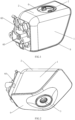
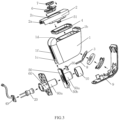
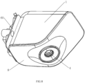
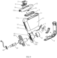
- the atomization device of the present disclosure includes a box body 1, a box cover 2 and an atomization sheet 3; an outlet 1a is formed on the box body 1, and the atomization sheet 3 is arranged at the outlet 1a; an abutment member and a snap-fit member are arranged between the box cover 2 and the box body 1; and when the box cover 2 and the box body 1 are installed, the box cover 2 is first abutted onto the box body 1 through the abutment member, and then the box cover 2 and the box body 1 are snap-fitted and fixed through the snap-fit member.
- the abutment member can be an abutment rib, or a structure in which an abutment rib matches with an abutment groove.
- an abutment rib can be formed on the box cover 2.
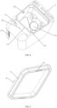
- An L-shaped abutment rib 2a is shown in FIGS. 3 and 6 .
- the L-shaped abutment rib 2a can be abutted against an edge of a box opening 1d formed on the box body 1 and matched with the box cover 2.
- the box cover 2 can be snap-fitted with the box body 1 through the snap-fit member so that the box cover 2 can cover and close the box opening 1d.
- the snap-fit member can be in the form of a claw matching with a snap-fit opening, or in the form of a snap-fit protrusion matching with a snap-fit groove, which can be flexibly set by those skilled in the art.
- a sealing member 4 is arranged between the box body 1 and the box cover 2, and a through opening 4a is formed on the sealing member 4;
- the snap-fit member includes a first snap-fit element 51 arranged on the box cover 2 and a second snap-fit element 52 arranged on the box body 1, and the first snap-fit element 51 passes through the through opening 4a and is snap-fitted and fixed with the second snap-fit element 52.
- the sealing member 4 can be a sealing ring, or a sealing gasket, or other sealing structures.
- the first snap-fit element 51 can not only be snap-fitted with the second snap-fit element 52 to achieve the installation of the box cover 2 and the box body 1, but also can position the sealing member 4 to prevent the sealing member 4 from moving when the box cover 2 covers and closes the box opening 1d.
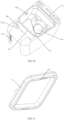
- a positioning protrusion 4b can also be formed on the sealing member 4, and a positioning groove 2b can be formed on the box cover 2. The positioning protrusion 4b is mated with the positioning groove 2b.
- sealing member 4 being a square ring-shaped sealing gasket as an example
- the mating between the first snap-fit elements 51 and the through opening 4a can achieve the positioning of one pair of sides of the square ring-shaped sealing gasket, and the mating between the positioning protrusions 4b and the positioning grooves 2b can achieve the positioning of the other pair of sides of the square ring-shaped sealing gasket, ensuring that all four sides of the square ring-shaped sealing gasket can be positioned and that the square ring-shaped sealing gasket will not move or deform.
- the number of the positioning protrusion 4b and the number of the positioning groove 2b can both be one.
- the first snap-fit element 51 is a snap-fit plate with a snap-fit opening
- the second snap-fit element 52 is a snap-fit protrusion.
- the snap-fit plate passes through the through opening 4a and exposes the snap-fit opening so that the snap-fit opening is snap-fitted with the snap-fit protrusion.
- the first snap-fit element 51 and the second snap-fit element 52 can also use other snap-fit methods.
- the snap-fit member can also directly snap-fit the box body 1 with the box cover 2 without mating with the sealing member 4.
- the atomization device further includes a feeding cover 6, and a feeding port 2c is formed on the box cover 2; a first spiral groove is formed on the feeding cover 6, a second spiral groove is formed on the feeding port 2c, and the feeding cover 6 is screw-connected with the feeding port 2c through the first spiral groove and the second spiral groove.
- the screw connection between the feeding cover 6 and the feeding port 2c enables the feeding cover 6 to screw in and out relative to the feeding port 2c. That is, rotating the feeding cover 6 in one direction enables the feeding cover 6 to screw in and close the feeding port 2c, and rotating the feeding cover 6 in the other direction enables the feeding cover 6 to screw out and open the feeding port 2c.
- the feeding cover 6 and the feeding port 2c can also adopt a flip over structure with a pivotal connection.
- an outer surface of the feeding cover 6 is rotatably connected with a handle ring 7, which can rotate in a non-pulling state and be accommodated in the feeding port 2c.
- the handle ring 7 can be connected to the outer surface of the feeding cover 6 through pivotal connection. After the feeding port 2c is closed by the feeding cover 6, the outer surface of the feeding cover 6 has a certain distance from an outer edge of the feeding port 2c. This distance ensures that the handle ring 7 in the non-pulling state can be accommodated. In this state, the plane where the handle ring 7 is located is parallel to the plane where the outer surface of the feeding cover 6 is located.
- the plane where the handle ring 7 is located is perpendicular to or at a certain angle to the plane where the outer surface of the feeding cover 6 is located, so that twisting the handle ring 7 enables the feeding cover 6 to screw out of the feeding port 2c.
- a water containing chamber 1b and an electrical chamber 1c isolated from each other are formed inside the box body 1.
- the outlet 1a is communicated with the water containing chamber 1b, and the electrical chamber 1c is used to accommodate a wire harness 8 connected with the atomization sheet 3.
- the electrical chamber 1c and the water containing chamber 1b can be separated by a partition structure 1e.
- the partition structure 1e, the box cover 2 and the feeding cover 6 ensure the closure of the water containing chamber 1b.
- the outlet 1a is formed on the partition structure 1e, and the electrical chamber 1c can be closed or non-closed.
- the partition structure is U-shaped, and the outlet 1a is formed at the bottom of the U-shaped partition structure.
- An accommodation groove is formed on an outer side of the bottom of the partition structure 1e, and the wire harness 8 can be partially accommodated in the accommodation groove, thereby positioning the wire harness 8.
- the atomization device further includes a wireless charging assembly for supplying power to the atomization sheet 3; the wireless charging assembly is connected with the box body 1, and a part of the wireless charging assembly is located inside the electrical chamber 1c.
- the wireless charging assembly can adopt electromagnetic induction wireless charging method, or magnetic resonance wireless charging method; of course, other wireless charging methods can also be used.
- the wireless charging assembly includes a fixed member, an induction coil 10, an inductive element 20, a first circuit board 30, and a second circuit board 40; the fixed member is arranged on other apparatuses, and the fixed member is connected with the box body 1; the induction coil 10 and the inductive element 20 are both arranged on the fixed member, and the induction coil 10 is sleeved on an outer side of the inductive element 20; the first circuit board 30 is connected with the induction coil 10, and the second circuit board 40 is connected with the inductive element 20.
- the fixed member can be a fixed bracket, or a fixed plate, or another fixed structure.
- the induction coil 10 is connected to the atomization sheet 3 through the wire harness 8, or the first circuit board 30 is connected to the atomization sheet 3 through the wire harness 8.
- the second circuit board 40 is connected to a power source through a wire harness.
- the inductive element 20 generates a certain current in the induction coil 10 through electromagnetic induction based on a certain frequency of AC electricity, thereby transferring electrical energy from the inductive element 20 to the induction coil 10, and achieving power supply to the atomization sheet 3.
- the arrangement of wire harness between the inductive element 20 and the induction coil 10 is omitted.
- wired connection can also be used to provide power to the atomization sheet 3.
- the fixed member includes a fixed inner plate 50 and a fixed outer plate 60; the fixed inner plate 50 is connected with the box body 1, and the fixed outer plate 60 is fixed on other apparatuses; the fixed outer plate 60 is formed with a first hollow columnar structure 60a, and the fixed inner plate 50 is formed with a second hollow columnar structure 50a; the second hollow columnar structure 50a is sleeved on the first hollow columnar structure 60a, the induction coil 10 is sleeved on the second hollow columnar structure 50a, and the inductive element 20 is arranged in the first hollow columnar structure 60a; the first circuit board 30 is arranged on the fixed inner plate 50, and the second circuit board 40 is arranged on the fixed outer plate 60.
- the first hollow columnar structure 60a is formed on a side of the fixed outer plate 60 that is close to the fixed inner plate 50.
- the second hollow columnar structure 50a is formed on a side of the fixed inner plate 50 that is away from the fixed outer plate 60.
- a diameter of outer tube wall of the first hollow columnar structure 60a is preferably equal to a diameter of inner tube wall of the second hollow columnar structure 50a, so that the first hollow columnar structure 60a and the second hollow columnar structure 50a can be positioned with each other.
- the first hollow columnar structure 60a and the second hollow columnar structure 50a are made of insulative materials such as glass, plastic, or ceramics. Not using metals can avoid electromagnetic shielding.
- the end of the first hollow columnar structure 60a and the end of the second hollow columnar structure 50a are preferably both closed.
- the fixed outer plate 60 can serve as an installation base for the fixed inner plate 50, and the fixed outer plate 60 can be fixed on other apparatuses.
- the fixed inner plate 50 can be detached from the fixed outer plate 60. Then during installation, the fixed inner plate 50 can be installed on the fixed outer plate 60.
- the first hollow columnar structure 60a and the second hollow columnar structure 50a can play a role of positioning during installation.
- the first hollow columnar structure 60a can accommodate the inductive element 20, and the induction coil 10 can be sleeved outside the second hollow columnar structure 50a, so that both the first hollow columnar structure 60a and the second hollow columnar structure 50a have multiple functions, thereby further improving the compactness of the atomization device.
- a magnetic adsorption structure can be arranged between the fixed inner plate 50 and the fixed outer plate 60.
- a first permanent magnet is arranged on the fixed outer plate 60
- a second permanent magnet is arranged on the fixed inner plate 50. The magnetic properties of the first permanent magnet and the second permanent magnet are opposite, thereby achieving magnetic adsorption fixation of the fixed inner plate 50 by the fixed outer plate 60.
- an installation port is formed on the box body 1, an installation rib is formed on an inner wall of the installation port, and an installation groove is formed at an edge of the fixed inner plate 50; the installation rib is arranged in the installation groove to fix the fixed inner plate 50 on the box body 1.
- the installation port can be a square port or a semi-circular port, as long as it can allow the fixed inner plate 50 to enter the installation port.
- the installation port is a square port, a U-shaped installation rib 1f is formed on the inner wall of the square port, and the edge of the fixed inner plate 50 is formed with a U-shaped installation groove 50b.
- the fixed inner plate 50 is inserted into the installation port from one side of the installation port, and two sides of the U-shaped installation rib 1f are first engaged with two sides of the U-shaped installation groove 50b through insertion. When inserted in place, all three sides of the U-shaped installation rib 1f are engaged with three sides of the U-shaped installation groove 50b through insertion.
- the decorative shell 9 can abut against the bottom of the fixed inner plate 50. That is, during installation, the fixed inner plate 50 is first installed on the box body 1, and then the decorative shell 9 is snap-fitted on the box body 1.
- the decorative shell 9 can not only bear the bottom of the fixed inner plate 50, but also can seal the electrical chamber 1c.
- the clothing treatment apparatus of the present disclosure includes a cabinet, a clothing treatment cylinder, and a door device; the clothing treatment cylinder is arranged in the cabinet, and a clothing throw-in port is formed on the cabinet; the door device is configured to open and close the clothing throw-in port, and the clothing throw-in port is connected with the clothing treatment cylinder through a connecting member; the clothing treatment apparatus further includes an atomization device accommodating a clothing treatment agent; the box body 1 of the atomization device is arranged on the clothing treatment cylinder, the door device and/or the connecting member, and the atomization device has at least one outlet 1a arranged toward an interior of the clothing treatment cylinder so that the atomization device can spray atomized gas into the clothing treatment cylinder.
- the clothing treatment cylinder is a drying cylinder.
- the drying cylinder is a single cylinder structure
- the box body 1 of the atomization device is preferably arranged on the door device and/or the connecting member.
- the connecting member is a front support structure of the clothing dryer.
- a front end of the front support structure is connected with the clothing throw-in port of the cabinet, and a rear end of the front support structure is connected with a front end of the drying cylinder through a dynamic sealing structure.
- the front support structure not only supports the front end of the drying cylinder, but also does not affect the rotation of the drying cylinder.
- the clothing treatment cylinder is a washing and drying cylinder
- the clothing treatment cylinder is a sleeve structure, that is, the clothing treatment cylinder has an outer cylinder and an inner cylinder (also known as a drum) rotatably arranged in the outer cylinder.
- the box body 1 of the atomization device can be arranged on the outer cylinder, the door device and/or the connecting member.
- the connecting member is a window gasket. A front end of the window gasket is connected with the clothing throw-in port, and a rear end of the window gasket is connected with the outer cylinder.
- the window gasket is used to ensure sealing between the outer cylinder and the clothing throw-in port.
- the clothing treatment agent can be water, or detergent, softener, softening agent, fragrance enhancer, or another clothing treatment solvent, or a mixture of the aforementioned water and solvents.
- the atomized gas is droplets with a large number of small particles formed. Since it is not easy to observe each small droplet with the naked eye, a gas like structure is formed.
- the atomization device can disperse the clothing treatment agent and dispense it onto the clothing in the clothing treatment cylinder.
- the present disclosure provides an atomization device and a clothing treatment apparatus, aiming to enrich the application scenes of atomization devices and facilitate the quick addition of solvent.
- the atomization device of the present disclosure includes a water box 1, a feeding cover 2, a handle ring 3 and an atomization sheet 4;
- the water box 1 is formed with a feeding port 1a and an outlet 1b, and the atomization sheet 4 is arranged at the outlet 1a;
- the handle ring 3 is connected with the feeding cover 2, a first spiral groove is formed on the feeding cover 2, and a second spiral groove is formed on the feeding port 1b;
- the feeding cover 2 is screw-connected with the feeding port 1b through the first spiral groove and the second spiral groove, and the handle ring 3 is arranged to enable the feeding cover 2 to screw in and out relative to the feeding port 1b.
- the screw connection between the feeding cover 2 and the feeding port 1b enables the feeding cover 2 to screw in and out relative to the feeding port 1b. That is, rotating the feeding cover 2 in one direction enables the feeding cover 2 to screw in and close the feeding port 1b, and rotating the feeding cover 2 in the other direction enables the feeding cover 2 to screw out and open the feeding port 1b.
- a handle ring 3 is rotatably connected with an outer surface of the feeding cover 2, and the handle ring 3 can rotate in a non-pulling state and be accommodated in the feeding port 1b.
- the handle ring 3 can be connected to the outer surface of the feeding cover 2 through pivotal connection. After the feeding port 1b is closed by the feeding cover 2, the outer surface of the feeding cover 2 has a certain distance from an outer edge of the feeding port 1b. This distance ensures that the handle ring 3 in the non-pulling state can be accommodated. In this state, the plane where the handle ring 3 is located is parallel to the plane where the outer surface of the feeding cover 2 is located.
- the handle ring 3 When the handle ring 3 is in a pulling state (for example, the handle ring 3 exposes the feeding port 1b, making it easier for the user to grip), the plane where the handle ring 3 is located is perpendicular to or at a certain angle to the plane where the outer surface of the feeding cover 2 is located, so that twisting the handle ring 3 enables the feeding cover 2 to screw out of the feeding port 1b.
- the handle ring 3 can also be connected with the feeding cover 2 by insertion or snap-fit, which can be flexibly set by those skilled in the art.
- a first sealing member is arranged between the feeding cover 2 and the feeding port 1b, and the first sealing member can be a sealing ring, a sealing gasket, or other sealing structures.
- an abutment rib can be formed on the box cover 12.
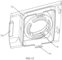
- An L-shaped abutment rib 12a is shown in FIGS. 9 and 12 .
- the L-shaped abutment rib 12a can be abutted against an inner side of an edge of a box opening 11a formed on the box body 11 and matched with the box cover 12.
- the box cover 12 can be snap-fitted with the box body 11 through the snap-fit member so that the box cover 12 can cover and close the box opening 11a.
- the snap-fit member can be in the form of a claw matching with a snap-fit opening, or in the form of a snap-fit protrusion matching with a snap-fit groove, which can be flexibly set by those skilled in the art.
- a second sealing member 5 is arranged between the box body 11 and the box cover 12, and a through opening 5a is formed on the second sealing member 5;
- the snap-fit member includes a first snap-fit element 61 arranged on the box cover 12 and a second snap-fit element 62 arranged on the box body 11, and the first snap-fit element 61 passes through the through opening 5a and is snap-fitted and fixed with the second snap-fit element 62.
- the second sealing member 5 can be a sealing ring, or a sealing gasket, or other sealing structures.
- the first snap-fit element 61 can not only be snap-fitted with the second snap-fit element 62 to achieve the installation of the box cover 12 and the box body 11, but also can position the second sealing member 5 to prevent the second sealing member 5 from moving when the box cover 12 covers and closes the box opening 11a.
- a positioning protrusion can also be formed on the second sealing member 5, and a positioning groove can be formed on the box cover 12. The positioning protrusion is mated with the positioning groove.
- the second sealing member 5 being a square ring-shaped sealing gasket as an example
- the mating between the first snap-fit element 61 and the through opening 5a can achieve the positioning of one pair of sides of the square ring-shaped sealing gasket, and the mating between the positioning protrusions and the positioning grooves can achieve the positioning of the other pair of sides of the square ring-shaped sealing gasket, ensuring that all four sides of the square ring-shaped sealing gasket can be positioned and that the square ring-shaped sealing gasket will not move or deform.
- the first snap-fit element 61 is a snap-fit plate with a snap-fit opening
- the second snap-fit element 62 is a snap-fit protrusion.
- the snap-fit plate passes through the through opening 5a and exposes the snap-fit opening so that the snap-fit opening is snap-fitted with the snap-fit protrusion.
- the first snap-fit element 61 and the second snap-fit element 62 can also use other snap-fit methods.
- the snap-fit member can also directly snap-fit the box body 11 with the box cover 12 without mating with the second sealing member 5.
- a water containing chamber 1c and an electrical chamber 1d isolated from each other are formed inside the water box 1.
- Both the feeding port 1b and the outlet 1a are communicated with the water containing chamber 1c, and the electrical chamber 1d is used to accommodate a wire harness 7 connected with the atomization sheet 4.
- the electrical chamber 1d and the water containing chamber 1c can be separated by a partition structure 1e.
- the partition structure 1e, the box cover 12 and the feeding cover 2 ensure the closure of the water containing chamber 1c.
- the outlet 1a is formed on the partition structure 1e, and the electrical chamber 1d can be closed or non-closed.
- a lower part of the electrical chamber 1d is closed by a decorative shell 8, and the electrical chamber 1d can accommodate the wire harness 7 connected with the atomization sheet 4, thereby achieving power supply and control of the atomization sheet 4.
- an accommodation groove is formed on an outer side of the partition structure 1e, and the wire harness 7 can be partially accommodated in the accommodation groove, thereby positioning the wire harness 7.
- the atomization device further includes a wireless charging assembly for supplying power to the atomization sheet 4; the wireless charging assembly is connected with the water box 1, and a part of the wireless charging assembly is located inside the electrical chamber 1d.
- the wireless charging assembly can adopt electromagnetic induction wireless charging method, or magnetic resonance wireless charging method; of course, other wireless charging methods can also be used. In a preferred case, as shown in FIG.
- the wireless charging assembly includes a fixed member, an induction coil 10, an inductive element 20, a first circuit board 30, and a second circuit board 40; the fixed member is arranged on other apparatuses, and the fixed member is connected with the water box 1; the induction coil 10 and the inductive element 20 are both arranged on the fixed member, and the induction coil 10 is sleeved on an outer side of the inductive element 20; the first circuit board 30 is connected with the induction coil 10, and the second circuit board 40 is connected with the inductive element 20.
- the fixed member can be a fixed bracket, or a fixed plate, or another fixed structure.
- the induction coil 10 is connected to the atomization sheet 4 through the wire harness 7, or the first circuit board 30 is connected to the atomization sheet 4 through the wire harness 7.
- the second circuit board 40 is connected to a power source through a wire harness.
- the inductive element 20 generates a certain current in the induction coil 10 through electromagnetic induction based on a certain frequency of AC electricity, thereby transferring electrical energy from the inductive element 20 to the induction coil 10, and achieving power supply to the atomization sheet 4.
- the arrangement of wire harness between the inductive element 20 and the induction coil 10 is omitted.
- wired connection can also be used to provide power to the atomization sheet 4.
- the fixed member includes a fixed inner plate 50 and a fixed outer plate 60; the fixed inner plate 50 is connected with the water box 1, and the fixed outer plate 60 is fixed on other apparatuses; the fixed outer plate 60 is formed with a first hollow columnar structure 60a, and the fixed inner plate 50 is formed with a second hollow columnar structure 50a; the second hollow columnar structure 50a is sleeved on the first hollow columnar structure 60a, the induction coil 10 is sleeved on the second hollow columnar structure 50a, and the inductive element 20 is arranged in the first hollow columnar structure 60a; the first circuit board 30 is arranged on the fixed inner plate 50, and the second circuit board 40 is arranged on the fixed outer plate 60.
- the first hollow columnar structure 60a is formed on a side of the fixed outer plate 60 that is close to the fixed inner plate 50.
- the second hollow columnar structure 50a is formed on a side of the fixed inner plate 50 that is away from the fixed outer plate 60.
- a diameter of outer tube wall of the first hollow columnar structure 60a is preferably equal to a diameter of inner tube wall of the second hollow columnar structure 50a, so that the first hollow columnar structure 60a and the second hollow columnar structure 50a can be positioned with each other.
- the first hollow columnar structure 60a and the second hollow columnar structure 50a are made of insulative materials such as glass, plastic, or ceramics. Not using metals can avoid electromagnetic shielding.
- an installation port is formed on the water box 1, an installation rib is formed on an inner wall of the installation port, and an installation groove is formed at an edge of the fixed inner plate 50; the installation rib is arranged in the installation groove to fix the fixed inner plate 50 on the water box 1.
- the installation port can be a square port or a semi-circular port, as long as it can allow the fixed inner plate 50 to enter the installation port.
- the installation port is a square port, a U-shaped installation rib 1f is formed on the inner wall of the square port, and the edge of the fixed inner plate 50 is formed with a U-shaped installation groove 50b.
- the fixed inner plate 50 is inserted into the installation port from one side of the installation port, and two sides of the U-shaped installation rib 1f are first engaged with two sides of the U-shaped installation groove 50b through insertion. When inserted in place, all three sides of the U-shaped installation rib 1f are engaged with three sides of the U-shaped installation groove 50b through insertion.
- the decorative shell 8 can abut against the bottom of the fixed inner plate 50. That is, during installation, the fixed inner plate 50 is first installed on the water box 1, and then the decorative shell 8 is snap-fitted on the water box 1.
- the decorative shell 8 can not only bear the bottom of the fixed inner plate 50, but also can seal the electrical chamber 1d.
- the clothing treatment apparatus of the present disclosure includes a cabinet, a clothing treatment cylinder, and a door device; the clothing treatment cylinder is arranged in the cabinet, and a clothing throw-in port is formed on the cabinet; the door device is configured to open and close the clothing throw-in port, and the clothing throw-in port is connected with the clothing treatment cylinder through a connecting member; the clothing treatment apparatus further includes an atomization device accommodating a clothing treatment agent; the water box 1 of the atomization device is arranged on the clothing treatment cylinder, the door device and/or the connecting member, and the atomization device has at least one outlet 1a arranged toward an interior of the clothing treatment cylinder so that the atomization device can spray atomized gas into the clothing treatment cylinder.
- the clothing treatment cylinder is a drying cylinder.
- the drying cylinder is a single cylinder structure
- the water box 1 of the atomization device is preferably arranged on the door device and/or the connecting member.
- the connecting member is a front support structure of the clothing dryer.
- a front end of the front support structure is connected with the clothing throw-in port of the cabinet, and a rear end of the front support structure is connected with a front end of the drying cylinder through a dynamic sealing structure.
- the front support structure not only supports the front end of the drying cylinder, but also does not affect the rotation of the drying cylinder.
- the clothing treatment cylinder is a washing and drying cylinder
- the clothing treatment cylinder is a sleeve structure, that is, the clothing treatment cylinder has an outer cylinder and an inner cylinder (also known as a drum) rotatably arranged in the outer cylinder.
- the water box 1 of the atomization device can be arranged on the outer cylinder, the door device and/or the connecting member.
- the connecting member is a window gasket. A front end of the window gasket is connected with the clothing throw-in port, and a rear end of the window gasket is connected with the outer cylinder.
- the window gasket is used to ensure sealing between the outer cylinder and the clothing throw-in port.
- the clothing treatment agent can be water, or detergent, softener, softening agent, fragrance enhancer, or another clothing treatment solvent, or a mixture of the aforementioned water and solvents.
- the atomized gas is droplets with a large number of small particles formed. Since it is not easy to observe each small droplet with the naked eye, a gas like structure is formed.
- the atomization device can disperse the clothing treatment agent and dispense it onto the clothing in the clothing treatment cylinder.
Landscapes
- Engineering & Computer Science (AREA)
- Textile Engineering (AREA)
- Detail Structures Of Washing Machines And Dryers (AREA)
- Accessory Of Washing/Drying Machine, Commercial Washing/Drying Machine, Other Washing/Drying Machine (AREA)
- Nozzles (AREA)
Applications Claiming Priority (3)
| Application Number | Priority Date | Filing Date | Title |
|---|---|---|---|
| CN202111523022.2A CN116289125A (zh) | 2021-12-13 | 2021-12-13 | 雾化装置和衣物处理设备 |
| CN202111542406.9A CN116263028A (zh) | 2021-12-13 | 2021-12-13 | 雾化装置和衣物处理设备 |
| PCT/CN2022/101712 WO2023109084A1 (zh) | 2021-12-13 | 2022-06-28 | 雾化装置和衣物处理设备 |
Publications (2)
| Publication Number | Publication Date |
|---|---|
| EP4450701A1 true EP4450701A1 (de) | 2024-10-23 |
| EP4450701A4 EP4450701A4 (de) | 2025-12-03 |
Family
ID=86775211
Family Applications (1)
| Application Number | Title | Priority Date | Filing Date |
|---|---|---|---|
| EP22905849.0A Pending EP4450701A4 (de) | 2021-12-13 | 2022-06-28 | Zerstäubungsvorrichtung und kleidungsbehandlungsvorrichtung |
Country Status (5)
| Country | Link |
|---|---|
| US (1) | US20260210023A1 (de) |
| EP (1) | EP4450701A4 (de) |
| JP (1) | JP7757580B2 (de) |
| AU (1) | AU2022410986B2 (de) |
| WO (1) | WO2023109084A1 (de) |
Family Cites Families (22)
| Publication number | Priority date | Publication date | Assignee | Title |
|---|---|---|---|---|
| JPS6039628U (ja) * | 1983-08-26 | 1985-03-19 | ニッスイ工業株式会社 | 広口冷水筒 |
| JPH049232Y2 (de) * | 1986-02-13 | 1992-03-09 | ||
| JP2006201277A (ja) * | 2005-01-18 | 2006-08-03 | Canon Inc | 撮像機器 |
| KR20090003043U (ko) * | 2007-09-21 | 2009-03-25 | 삼성전자주식회사 | 의류건조기 |
| KR20090035901A (ko) * | 2007-10-08 | 2009-04-13 | 엘지전자 주식회사 | 세탁물 처리장치 |
| EP2175065B1 (de) * | 2008-10-08 | 2014-01-15 | Candy S.p.A. | Waschmaschinenkonditionierungsvorrichtung |
| CN202015670U (zh) * | 2011-03-28 | 2011-10-26 | 广州优创电子有限公司 | 一种超声波雾化器 |
| DE102011084265A1 (de) * | 2011-10-11 | 2013-04-11 | BSH Bosch und Siemens Hausgeräte GmbH | Wasserführendes Haushaltsgerät mit einer Vernebelungseinrichtung sowie Verfahren zu seinem Betrieb |
| MX2016007249A (es) * | 2013-12-05 | 2017-01-05 | 3M Innovative Properties Co | Contenedor para dispositivo atomizador. |
| JP3202226U (ja) * | 2015-11-09 | 2016-01-28 | 株式会社ドウシシャ | 除菌機能を有する加湿器 |
| JP2017190934A (ja) * | 2016-04-15 | 2017-10-19 | フィーネ株式会社 | 給水ボトル、空気清浄器及び加湿器 |
| CN207653770U (zh) * | 2017-12-27 | 2018-07-27 | 小熊电器股份有限公司 | 一种补水仪 |
| CN208104822U (zh) * | 2018-04-11 | 2018-11-16 | 刘旭阳 | 一种多功能衣物护理装置 |
| CN108679765A (zh) * | 2018-06-13 | 2018-10-19 | 深圳市鑫华昌科技有限公司 | 一种瀑布景观加湿器 |
| CN208449737U (zh) * | 2018-06-21 | 2019-02-01 | 赵宣玉 | 喷雾通用接头改良结构及其应用 |
| CN209475303U (zh) * | 2018-07-25 | 2019-10-11 | 四川爱创科技有限公司 | 液体雾化装置组装结构 |
| CN111334964B (zh) * | 2018-12-19 | 2025-04-22 | 合肥海尔滚筒洗衣机有限公司 | 衣物处理设备 |
| CN111691135B (zh) * | 2019-03-14 | 2023-03-28 | 青岛海尔洗衣机有限公司 | 用于衣物处理设备的雾化装置及衣物处理设备 |
| CN111691109A (zh) * | 2019-03-14 | 2020-09-22 | 青岛海尔洗衣机有限公司 | 用于衣物处理设备的雾化装置 |
| CN210020700U (zh) * | 2019-04-04 | 2020-02-07 | 周宏亮 | 一种分体式雾化器 |
| CN212262081U (zh) * | 2020-03-17 | 2021-01-01 | 深圳市贝格美科技有限公司 | 一种可更换超声雾化片的手持雾化器 |
| CN214181366U (zh) * | 2020-10-12 | 2021-09-14 | 中山蓝网物联技术有限公司 | 一种便携式超声波雾化器 |
-
2022
- 2022-06-28 WO PCT/CN2022/101712 patent/WO2023109084A1/zh not_active Ceased
- 2022-06-28 EP EP22905849.0A patent/EP4450701A4/de active Pending
- 2022-06-28 JP JP2024535876A patent/JP7757580B2/ja active Active
- 2022-06-28 AU AU2022410986A patent/AU2022410986B2/en active Active
- 2022-06-28 US US18/719,569 patent/US20260210023A1/en active Pending
Also Published As
| Publication number | Publication date |
|---|---|
| WO2023109084A1 (zh) | 2023-06-22 |
| EP4450701A4 (de) | 2025-12-03 |
| US20260210023A1 (en) | 2026-07-23 |
| JP7757580B2 (ja) | 2025-10-22 |
| JP2024544292A (ja) | 2024-11-28 |
| AU2022410986A1 (en) | 2024-06-27 |
| AU2022410986B2 (en) | 2026-05-07 |
Similar Documents
| Publication | Publication Date | Title |
|---|---|---|
| CN217266437U (zh) | 衣物处理设备 | |
| WO2020182007A1 (zh) | 用于衣物处理设备的雾化装置 | |
| CN217266509U (zh) | 雾化装置和衣物处理设备 | |
| CN217266510U (zh) | 衣物处理设备 | |
| CN111691135A (zh) | 用于衣物处理设备的雾化装置及衣物处理设备 | |
| AU2022410986B2 (en) | Atomization apparatus and clothing treatment device | |
| EP4455397A1 (de) | Kleidungsbehandlungsausrüstung, kleidungsbehandlungsverfahren und zerstäubungsvorrichtung | |
| CN116536886A (zh) | 衣物处理设备 | |
| WO2023142365A1 (zh) | 雾化装置和衣物处理设备 | |
| WO2023142362A1 (zh) | 雾化装置和衣物处理设备 | |
| CN116263028A (zh) | 雾化装置和衣物处理设备 | |
| WO2023035724A1 (zh) | 衣物处理设备 | |
| CN116289125A (zh) | 雾化装置和衣物处理设备 | |
| CN116263025A (zh) | 雾化装置和衣物处理设备 | |
| CN116263023A (zh) | 雾化装置和衣物处理设备 | |
| CN116263022A (zh) | 衣物处理设备及其衣物处理方法 | |
| AU2022343213B2 (en) | Clothing treatment device and clothing treatment method thereof | |
| CN116263024A (zh) | 雾化装置和衣物处理设备 | |
| CN116536884A (zh) | 衣物处理设备 | |
| CN116536889A (zh) | 衣物处理设备 | |
| WO2023035734A1 (zh) | 衣物处理设备 | |
| CN116536885A (zh) | 衣物处理设备 | |
| CN217091684U (zh) | 带滑盖控制的弹夹式补水仪 | |
| CN212349163U (zh) | 喷雾器 | |
| CN121428796B (zh) | 一种衣物处理设备 |
Legal Events
| Date | Code | Title | Description |
|---|---|---|---|
| STAA | Information on the status of an ep patent application or granted ep patent |
Free format text: STATUS: THE INTERNATIONAL PUBLICATION HAS BEEN MADE |
|
| PUAI | Public reference made under article 153(3) epc to a published international application that has entered the european phase |
Free format text: ORIGINAL CODE: 0009012 |
|
| STAA | Information on the status of an ep patent application or granted ep patent |
Free format text: STATUS: REQUEST FOR EXAMINATION WAS MADE |
|
| 17P | Request for examination filed |
Effective date: 20240613 |
|
| AK | Designated contracting states |
Kind code of ref document: A1 Designated state(s): AL AT BE BG CH CY CZ DE DK EE ES FI FR GB GR HR HU IE IS IT LI LT LU LV MC MK MT NL NO PL PT RO RS SE SI SK SM TR |
|
| DAV | Request for validation of the european patent (deleted) | ||
| DAX | Request for extension of the european patent (deleted) | ||
| REG | Reference to a national code |
Ref country code: DE Ref legal event code: R079 Free format text: PREVIOUS MAIN CLASS: D06F0039020000 Ipc: D06F0058200000 |
|
| A4 | Supplementary search report drawn up and despatched |
Effective date: 20251031 |
|
| RIC1 | Information provided on ipc code assigned before grant |
Ipc: D06F 58/20 20060101AFI20251027BHEP |